manuals.online logo
Brands
  1. Home
  2. •
  3. Brands
  4. •
  5. InMotion
  6. •
  7. Security Camera
  8. •
  9. InMotion in52TS3N2D Series User manual

InMotion in52TS3N2D Series User manual

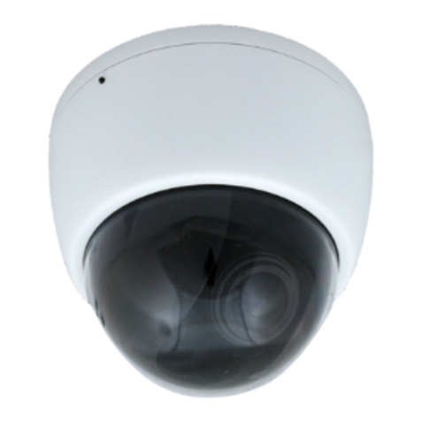
in52TS3N2D Series
Tamper Resistant Dome Camera
Quick Start Guide
Before operang this product, please read this quick-start guide to ensure proper use.
Please store these instrucons a safe place for future reference.
FEATURES
• Polycarbonate Housing &Bubble
• DC Varifocal lens
• 800TVL
• 0.01 Lux
• Wide Dynamic Range
• HLC, BLC, DEFOG
• Sens Up
• On Screen Menu
• 3 Axis gimbal
• 12VDC/24VAC Powered
PRECAUTIONS
1. Before installing and operang the unit, please read this manual carefully.
2. Precision components are contained in this camera, please avoid violent vibraons during
installaon and maintenance. Do not connect the power unl you have completed the
installaon.
3. Please obey all local electrical wiring regulaons when using this unit.
4. Do not use abrasive or corrosive materials for cleaning. Use only a so cloth for cleaning.
5. To prevent damage to the lens or sensor, do not point the camera directly into the sun
or very strong light sources.
6. Do not use the camera outside it’s working temperature (-10°C~ 50°C / 14°F ~122°F) or
humidity (<90%) ranges.
7. Ensure that the power supply meets the current requirements of the camera and that
the supply voltage is inside the tolerances of the camera: 12vdc or 24VAC ±10%
8. Ensure that the xings used are adequate to support the load of camera.
9. In case of camera failure, do not aempt to dismantle or service the camera yourself.
Please refer to qualied service personnel for repair of the camera.
CONNECTIONS
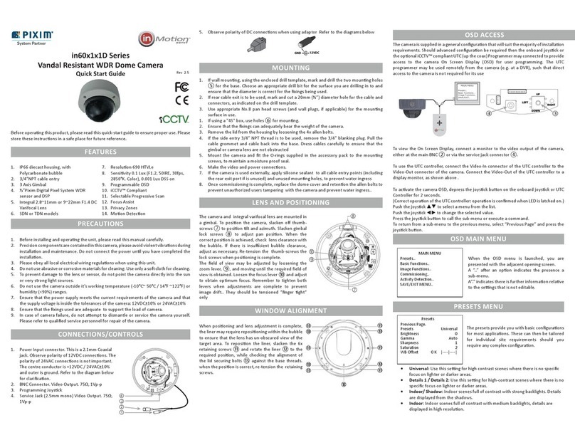
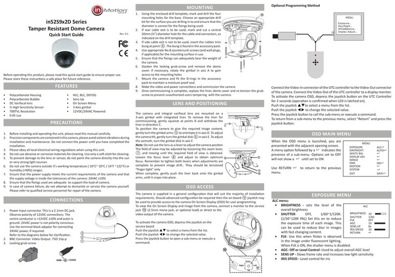
1. Power Input connector. This is a 2 pin non-removable terminal screw connector.
Observe polarity of 12VDC connecons. 24VAC power is not polarity sensive.
Refer to the diagrams below for claricaon.
2. BNC Connector, Video Output. 75Ω 1Vp-p
3. Locking grub-screw
+ (Pos)
- (Neg)
MOUNTING
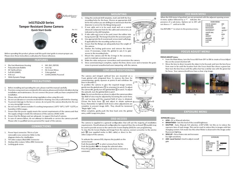
1. Using the enclosed drill template, mark and drill the four
mounng holes for the base. Choose an appropriate drill
bit for the surface you are drilling in to and ensure that the
diameter is correct for the xings being used.
2. If rear cable exit is to be used, mark and cut a central
20mm (¾”) diameter hole for the cable and connectors, as
indicated on the drill template.
3. Side cable exit. ④
4. Use appropriate No.8 countersunk screws (and wall plugs,
if applicable) for the mounng surface in use.
5. Ensure that the xings can adequately bear the weight of
the camera.
6. Slacken the locking grub-screw and remove the dome
cover. If necessary, rotate the gimbal in axis A to gain
access to the mounng holes
7. Mount the camera and t the O-rings in the accessory
pack to maintain a moisture proof seal.
8. Make the video and power connecons and commission the camera
9. Once commissioning is complete, replace the liner, dome cover and re-tension the grub-
screw to prevent unauthorized users tampering with the camera.
LENS AND POSITIONING
The camera and integral vari-focal lens are mounted on a
3-axis gimbal with integrated liner. To remove the liner for
commissioning, gently squeeze at points B and withdraw the
liner in direcon C.
To posion the camera to give the required image content,
gently turn the gimbal arms ⑤ to orientate it in axis D. To adjust
the camera lt, gently turn the gimbal disk ⑥ in axis E. To adjust
the azimuth, turn the gimbal disk in axis F.
Note: Do not use the lens as a lever to adjust the camera posion
The eld of view may be adjusted by loosening the zoom lever,
⑦, and moving until the required field of view is obtained.
Loosen the focus lever ⑧ and adjust to obtain optimum
focus. Remember to tighten both levers when adjustments are
complete to prevent image drift.. They should be tensioned
“nger ght“ only
When complete, gently push the liner back onto the gimbal
arms, unl it snaps into place.
OSD ACCESS
The camera is supplied in a general conguraon that will suit the majority of installaon
requirements. Should advanced conguraon be required then the on-board ⑨ joysck may
be used to provide access to the camera On Screen Display (OSD) for user programming.
To view the On Screen Display and image from the camera, connect a monitor to the service
jack ⑩ (use supplied molex to BNC cable) or direct to the video output of the camera.
To acvate the camera OSD, depress the joysck on the
service board
Push the joysck  to select a menu from the list.
Push the joysck  to change the selected value.
Press the joysck buon to open a sub-menu or execute a
command.
A
④
B
C
B
D
F
E
⑤
⑦
⑧
⑥
When the OSD menu is launched, you are
presented with the adjacent opening screen.
A menu opon followed by a  indicates the
presence of a sub-menu. Options set to OFF will
not show a  until set to ON
Use RETURN  to return to the previous menu.
FOCUS ADJUST menu:
• From the Main Menu, turn the Focus ADJ from OFF to ON to create a Focus Adjust
Box on the screen’s bottom left
• Move the lens to direct towards the object to be focused, and turn the lens focus
from near to far until the location from the Focus Assist Box shows a green bar.
Next turn the lens focus until the yellow bar has a similar size with the green bar
for focus. Your camera should now have a clear crisp image.
LENS menu:
• MODE - ALC (Auto Iris) or ELC (Manual)
selection
• INDOOR -Default, set to fixed values
• OUTDOOR- Iris and shutter will auto
adjust to lighting situation.
EXPOSURE menu:
• BRIGHTNESS - Sets the level of the overall brightness
• SHUTTER - Auto, Manual, FLK selection,
1/50~1/60K. Set this on to reduce the
exposure time of each image. This can be
used to reduce blur in images with fast
changing content. FLK mode Use this when
flicker is observed in the image under
fluorescent lighting.
• SENS UP - Slows frame rate and increases
low light sensitivity
• AGC- Level Control -Used to adjust overall
gain
Rev 0.1
MAIN MENU
FOCUS ADJUST 
EXPOSURE. ALC
BACKLIGHT WDR
DAY&NIGHT 
WHITE BAL AUTO
IMAGE 
DNR MIDDLE
SPECIAL 
SYSTEM 
EXIT
EXPOSURE
BRIGHTNESS 10
SHUTTER AUTO 
SENS-UP X2
AGC 16
RETURN RET
FOCUS ADJUST MENU
EXPOSURE MENU
OSD MAIN MENU



LENS MENU
LENS
MODE INDOOR
RETURN RET
BACKLIGHT - OFF, WDR, BLC, HLC
• WDR - Used to improve contrast in
bright/dark areas.
• BLC -Adjust the area to be enhanced
and sets the level
• HLC -is the ability to reverse bright
points to black or gray, (areas such
as headlights, any high luminance areas) this function will improve the
overall picture.
DAY/NIGHT - AUTO, COLOR, B/W, EXT
• AUTO - Allows the camera to switch
from color to B/W mode in low light.
The switching thresholds and hysteresis
time are adjustable.
• COLOR - Fixes the camera in color mode
• B/W - Fixes the camera in monochrome
mode.
• Ext - NA
WHITE BALANCE MENU
WHITE BALANCE - AUTO, AUTO-EXT , PRESET, MANUAL
• AWB -AUTO (default) The camera automatically samples the image for
optimum white balance
• AUTO EXT - The camera automatically
samples the image for optimum white
balance in an exterior environment.
• PRESET - Allows the white balance to
be set automatically and locked. This
option is normally used when no white
reference is present in the image. To
set the white balance, hold a white
object in front of the camera, with light from the source falling on it and
press the joystick to set and lock the white balance
• MANUAL - This option allows a selection of color temperature, Red and
Blue gain to be manually set in the image. Note, using this option requires
care to ensure all cameras on one system have the same color response.
IMAGE
IMAGE - Press to open submenu.
• SHARPNESS - Level control
• GAMMA - Level Control
• PEDESTAL - Level Control
• COLOR GAIN -Level control
• MIRROR - Horizontal flip of image
• FLIP - Vertical flip of image
DNR - OFF, LOW, MIDDLE, HIGH
• This function is used to improve the picture quality by filtering the noise
which is generated under low light conditions
SPECIAL - Press to open submenu.
• D-ZOOM - Digital zoom
• DNR - OFF, LOW, MIDDLE, HIGH
• ACE - Adaptive contrast enhancer,
preserves fine details, reduces artifacts
and loss of local contrast in the image
areas of bright/dark.
• DEFOG- Used to help improve the
captured image in poor weather
conditions such as smog, fog, or smoke.
It automatically controls contrast ratio
by spatially analyzing the histogram characteristics.
• SHADING -Compensates for the dark area created by the outline of the lens.
Compensation uses 2D gain table. Users can control 0 ~ 100% compensation
rate according to shading weight
• PRIVACY - Set up to 16 privacy zones
• INTELLIGENT -Set Motion Zones, Sensitivity, Response
SYSTEM - Press to open submenu.
• COM - Set com port and speed
• VIEW ANGLE - Select Normal, Wide 4:3
or Wide 16:9
• XY ADJUST-Adjust position of image
• CVBS - CCTV System PAL or NTSC
• LANGUAGE- Select from 5 languages
• CAMERA TITLE - Display title for camera
• RESET- Factory default, Press and hold enter
to reset.
System NTSC
Imaging Sensor Mega Pixel Sensor
Resoluon 800TVL
Sensivity 0.01Lux
Wide Dynamic Range 120dB Max
S/N Rao 52dB
Day / Night Mechanical
Lens Type 2.8~12mm DC Varifocal
Mount 14mm straight
Funcons OSD Multiple Languages
Shuer 1/50~1/60,000
Flickerless On/O
Wide Dynamic Range O Low/Middle/High
DEFOG Auto/Manual/Low/Medium/High
AGC Adjustable Level
SENS UP Adjustable Level 64x
Electronic shuer Auto,Flicker, Manual
Sync Internal
Camera ID Number O/On 0~255
Camera Name O/On, 8 Characters
White Balance Auto, Autoext, Preset, Manual
DNR Low, Medium, High
Gamma 0.45, 0.5, 0.55, 0.6, 0.65
Moon Detecon O/On, Posion & Sensivity
Digital Zoom Yes
Privacy masking O/On , areas, Color, Posion
Image funcons Sharpness, Mirror, Defog, HLC, BLC,
D-Zoom, Shade Comp
Input/Output Video Output CVBS 1.0Vp-p 75Ω - BNC
CVBS 1.0Vp-p 75Ω - Service port
Programming interface On board joysck
Power D Model 12VDC/24VAC ±10% 4.2W max
Physical Construcon Polycarbonate Shell & Bubble
Dimensions (mm) 108Ø x 95mmH (4.24”Ø x 3.47”H)
Weight 450g (.992 lb)
Mounng Surface
Environmental Operang Temperature -10°C~+50°C
Humidity Less than 90%, non condensing
Order Codes Lens 2.8~12mm in52TS3N2D28V12
inMoon CCTV
519 Bennet Lane
Suite 100
Lewisville, Texas 75057
214-960-4640
Please visit our website for full informaon: www.inMooncctv.com
inMoon reserves the right to amend specicaons and design without prior noce
SPECIAL
D-ZOOM 1.0X
ACE OFF
DEFOG OFF
SHADING OFF
PRIVACY OFF
INTELLIGENT OFF
RETURN 
WDR
WEIGHT MIDDLE
RETURN RET
SPECIFICATIONS
DAY/NIGHT
MODE AUTO
IR LED OFF
ANTI-SAT 9
EXTERN S/W NONE
AGC THRES 11
AGC MARGIN 8
DELAY HIGH
RETURN 
WHITE BAL
AWB Auto
RETURN 
DNR
SYSTEM
BACKLIGHT
SPECIAL
SYSTEM
COM 
VIEW ANGLE NORMAL
XY ADJUST 
CVBS NTSC
LANGUAGE ENG
CAM TITLE OFF
RESET ON
RETURN 
DAY&NIGHT
IMAGE
SHARPNESS [ 5]
GAMMA 0.45
PEDESTAL [ 8]
COLOR GAIN [ 10]
MIRROR OFF
FLIP OFF
RETURN 

Other InMotion Security Camera manuals

InMotion inHS2 1L30 Series User manual

InMotion

InMotion inHS2 1L30 Series User manual

InMotion in51x1x1D Series User manual

InMotion

InMotion in51x1x1D Series User manual

InMotion in10S1P1L User manual

InMotion

InMotion in10S1P1L User manual

InMotion in10S4x2L User manual

InMotion

InMotion in10S4x2L User manual

InMotion in52S8x2D Series User manual

InMotion

InMotion in52S8x2D Series User manual

InMotion in51S1P1D28V11 User manual

InMotion

InMotion in51S1P1D28V11 User manual

InMotion in10S3P2L User manual

InMotion

InMotion in10S3P2L User manual

InMotion in30S1P1L25 User manual

InMotion

InMotion in30S1P1L25 User manual

InMotion in30S1x1L User manual

InMotion

InMotion in30S1x1L User manual

InMotion in60x1x1D Series User manual

InMotion

InMotion in60x1x1D Series User manual

InMotion inTC Series User manual

InMotion

InMotion inTC Series User manual

InMotion in21 Series User manual

InMotion

InMotion in21 Series User manual

InMotion in51TS2x2D Series User manual

InMotion

InMotion in51TS2x2D Series User manual

InMotion in51S9P2D28V12 User manual

InMotion

InMotion in51S9P2D28V12 User manual

InMotion in4 S1P1L Series User manual

InMotion

InMotion in4 S1P1L Series User manual

InMotion in51S3P2D28V22 User manual

InMotion

InMotion in51S3P2D28V22 User manual

InMotion in10S2x2L User manual

InMotion

InMotion in10S2x2L User manual

InMotion in52S9x2D Series User manual

InMotion

InMotion in52S9x2D Series User manual

InMotion in71TS3N2D Series User manual

InMotion

InMotion in71TS3N2D Series User manual

InMotion in51S2x2D Series User manual

InMotion

InMotion in51S2x2D Series User manual

InMotion in45S3 2 Series User manual

InMotion

InMotion in45S3 2 Series User manual

Popular Security Camera manuals by other brands

LTS CMHR92T2-6 user manual

LTS

LTS CMHR92T2-6 user manual

GW Security 57 Series quick start guide

GW Security

GW Security 57 Series quick start guide

JVC VN-V25U VN-V26U Specifications

JVC

JVC VN-V25U VN-V26U Specifications

SIBELL TVIOB-SB2IRZW user manual

SIBELL

SIBELL TVIOB-SB2IRZW user manual

Vitek Mighty VTD-MVP2810/L35 Specifications

Vitek

Vitek Mighty VTD-MVP2810/L35 Specifications

dallmeier DDZ5200HD Series Commissioning

dallmeier

dallmeier DDZ5200HD Series Commissioning

Lorex SG6173 Quick setup guide

Lorex

Lorex SG6173 Quick setup guide

Clover HDC041 Specifications

Clover

Clover HDC041 Specifications

visual engineering surveillance camera user manual

visual engineering

visual engineering surveillance camera user manual

Cisco TelePresence MX700 installation guide

Cisco

Cisco TelePresence MX700 installation guide

General Lock WP-380 user manual

General Lock

General Lock WP-380 user manual

Vista 1080BIR35V16e quick guide

Vista

Vista 1080BIR35V16e quick guide

Avigilon H4A-G-BO1-IR installation guide

Avigilon

Avigilon H4A-G-BO1-IR installation guide

Novus NVIP-2ATM-4401 user manual

Novus

Novus NVIP-2ATM-4401 user manual

Panasonic BL-C10A - Network Camera - Pan operating instructions

Panasonic

Panasonic BL-C10A - Network Camera - Pan operating instructions

Vivotek IB9368 Series user manual

Vivotek

Vivotek IB9368 Series user manual

CP Plus Ezykam EPK-HC10L1 instruction manual

CP Plus

CP Plus Ezykam EPK-HC10L1 instruction manual

K&F Concept DQ201 quick start guide

K&F Concept

K&F Concept DQ201 quick start guide

manuals.online logo
manuals.online logoBrands
  • About & Mission
  • Contact us
  • Privacy Policy
  • Terms and Conditions

Copyright 2025 Manuals.Online. All Rights Reserved.