manuals.online logo
Brands
  1. Home
  2. •
  3. Brands
  4. •
  5. InMotion
  6. •
  7. Security Camera
  8. •
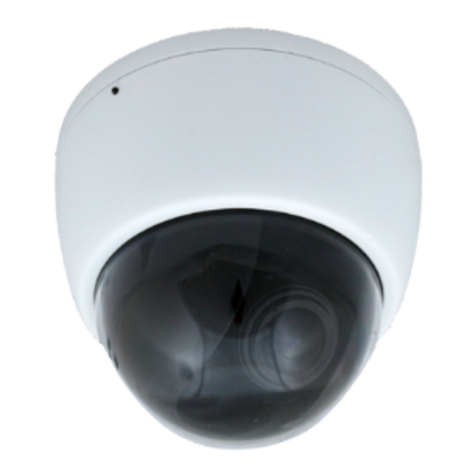
  9. InMotion in45S3 2 Series User manual

InMotion in45S3 2 Series User manual

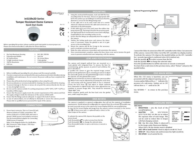
LENS ADJUSTMENT & POSITIONING
The camera and integral varifocal lens are mounted on a 3 axis gimbal. To gain
access to the camera, remove the liner by gently squeezing the liner at points ①
and lifting the liner off in direction ②.
To posion the camera, rotate the main gimbal in axis "A" by gripping and rotang
the gimbal arms ③, to rotate in axis "B" rotate the bars ④ on the gimbal disk, to
lt the camera in axis "C", rotate the edge of the gimbal disk ⑤, unl the desired
posion is obtained
The eld of view may be adjusted by loosening the zoom lever, ⑥, and moving
until the required field of view is obtained. Loosen the focus lever ⑦ and adjust
to obtain optimum focus. Remember to tighten both levers when adjustments
are complete to prevent image drift. The levers should be tensioned “nger ght“
only. Replace the liner by aligning and pressing gently in direcon ⑧ unl the
liner snaps back into place.
OSD ACCESS
Connect the Video-Out of the camera to a display monitor.
To acvate the camera OSD, depress the joysck buon on the in-line
cable joysck.
Push the joysck  to select a menu from the list.
Push the joysck  to change the selected value.
Press the joysck buon to open a sub-menu or execute a command.
OSD MAIN MENU
When the OSD menu is launched, you are
presented with the adjacent opening screen.
A menu opon followed by a  the presence
of a sub-menu.
An option in () indicates the feature is locked by
another setting and cannot be adjusted.
A indicates return to previous menu.
IRIS MENU
• IRIS ADJ - ELC/ALC (default). Select ALC when using a DC lens
• ALC menu:
• DC Level - sets the level of the iris when
using a DC lens.
• FLK- ON or OFF. On sets flickerless mode,
use this when flicker is observed in the
image under fluorescent lighting. When
FLK is ON, the shutter menu is disabled.
• Shutter: OFF, 1/120~1/120K. Set this
on to reduce the exposure time of each
image. This can be used to reduce blur in images with fast changing
content.
• ELC Menu: Use this option for fixed or manual iris lenses
• Brightness: sets the exposure of the image.
①
①
②
⑧
BOTTOM

A
B
C
④
⑤
⑦
⑥
③
UP
DOWN
L R
CAMERA MENU
IRIS ALC
AGC ADJ (ON)
DAY/NIGHT AUTO
WHITE BAL ATW
DNR MIDDLE
PICTURE ADJ 
OTHER SET 
EXIT SAVE
LENS SET
DC LEVEL [ 8]
FLK OFF
SHUTTER OFF
 
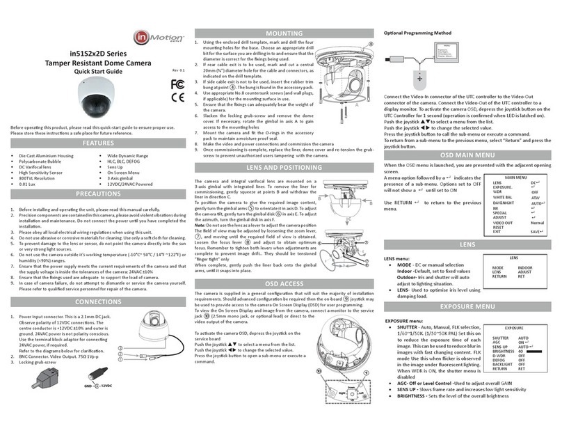
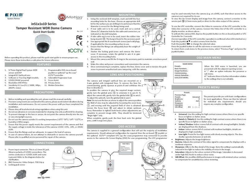
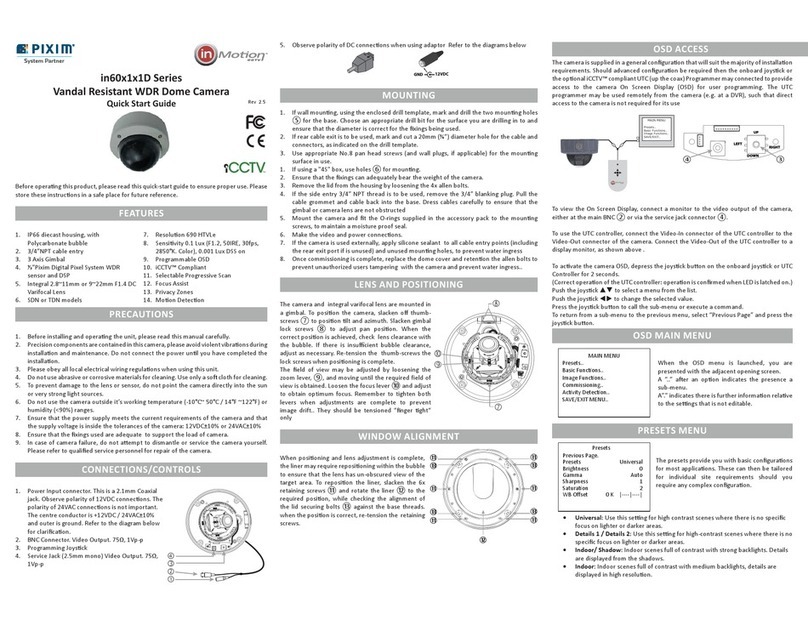
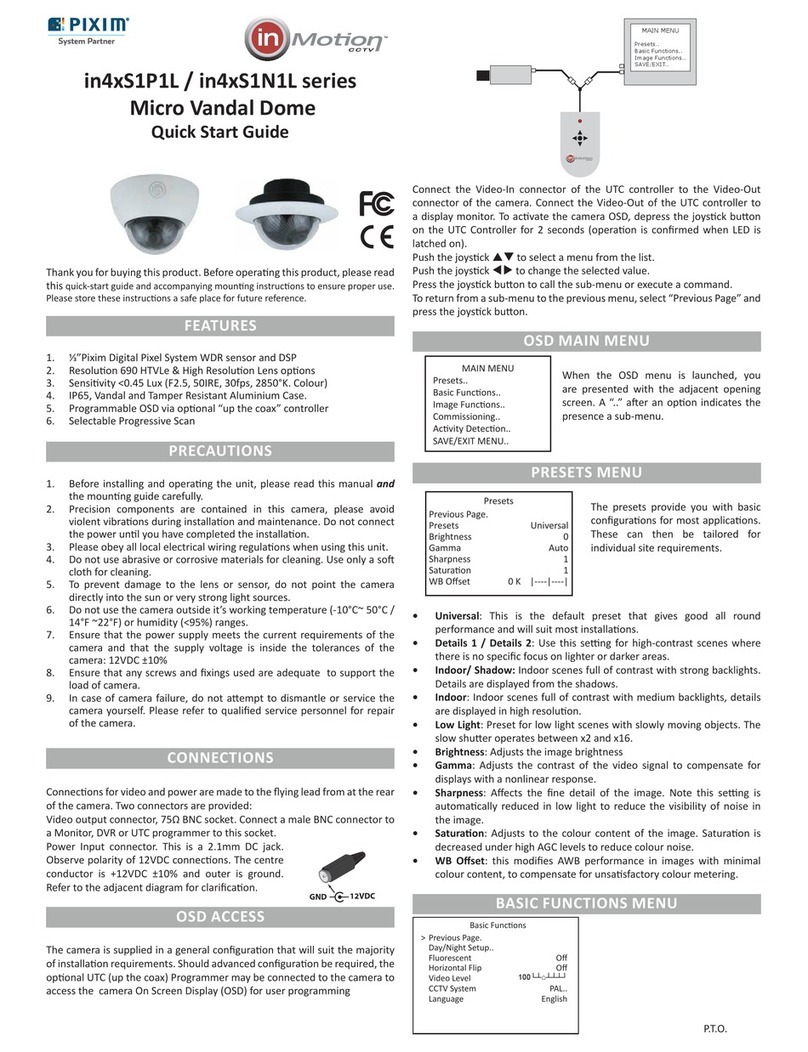
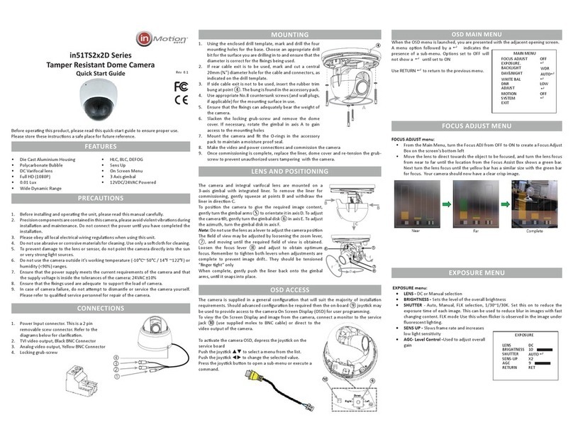
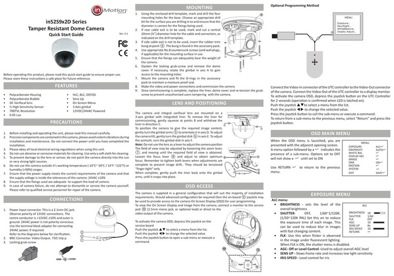
in45S3x2x Series
Tamper Resistant CCD Dome Camera
Quick Start Guide
Rev0.3
Before operang this product, please read this quick-start guide to ensure proper
use. Please store these instrucons a safe place for future reference.
FEATURES
• Polycarbonate Housing
• DC Varifocal lens
• ⅓” Sony SuperHAD II CCD
• 600TVL Resolution
• 0.05 Lux @ 50IRE Sensitivity
• Wide Extended Range
• Privacy Masking
• On Screen Menu
• 3 Axis gimbal
• 12VDC/24VAC Powered (D Model)
• 12VDC Powered (L Model)
PRECAUTIONS
1. Before installing and operang the unit, please read this manual carefully.
2. Precision components are contained in this camera, please avoid violent
vibraons during installaon and maintenance. Do not connect the power
unl you have completed the installaon.
3. Please obey all local electrical wiring regulaons when using or installing this
unit.
4. Do not use abrasive or corrosive materials for cleaning. Use only a so cloth
for cleaning.
5. To prevent damage to the lens or sensor, do not point the camera directly into
the sun or very strong light sources.
6. Do not use the camera outside it’s working temperature (-10°C~ 50°C / 14°F
~22°F) or humidity (<90%) ranges.
7. Ensure that the power supply meets the current requirements of the camera
and that the supply voltage is inside the tolerances of the camera model
12VDC±10% or 24VAC±10%
8. Ensure that any mounng xings used are adequate to support the load of
camera.
9. In case of camera failure, do not aempt to dismantle or service the camera
yourself. Please refer to qualied service personnel for repair of the camera.
CONNECTIONS/CONTROLS
1. In-line cable OSD joysck
2. Power Input connector. This is a 2.1mm
Coaxial jack. Observe polarity of 12VDC
connecons. The polarity of 24VAC
connecons is not important.
The centre conductor is +12VDC /
24VAC±10% and outer is ground. Refer to
the adjacent diagram for claricaon.
3. BNC Connector. Video Output. 75Ω, 1Vp-p



RELEASING THE COVER
1. The rear of the dome is cover marked with a  as indicated by ① above
2. Depress the release buon ② and gently li the lid in the direcon ③ unl
resistance is felt.
3. Push the  on the cover in direcon ④ and the front of the cover will
release from the base.
4. Li the cover o in direcon ⑤
RELEASING THE MOUNTING PLATE
1. Release and remove the cover as detailed above.
2. While holding the base plate insert ⑨, pull lever ⑥ in direcon ⑦and turn
the base counter clockwise ⑧, unl it stops, and then pull the plate from
the base
MOUNTING
1. N.B. When considering a mounng posion, ensure the chosen locaon
provides open access to the release buon. If the buon is obstructed, it will
not be possible to open the housing for maintenance.
1. Using the enclosed drill template, mark and drill the three mounng holes for
the base. Choose an appropriate drill bit for the surface you are drilling in to
and ensure that the diameter is correct for the xings being used.
2. Open a hole large enough to pass the power / video / and joysck through the
mounng surface.
3. Use appropriate No.8 screws (and wall plugs, if applicable) for the mounng
surface in use.
4. Ensure that the xings can adequately bear the weight of the camera.
5. Mount the camera base plate ⑨
6. Pass the cables through the hole made in 2., align the camera base with the
plate and rotate the base clockwise unl it clicks into place.
7. Make the power and video connecons and set up the camera as appropriate.
8. Once commissioning is complete, replace the dome cover by aligning the 
on the cover with the release buon and applying even pressure on the cover
rim ⑩ to snap it home.

⑩ ⑩



CAMERA
FRONT
BOTTOM
⑥
⑦
⑧
CAMERA
FRONT
Base Plate
⑨
12VDC
GND
AGC ADJ MENU
• AGC ADJ - ON or OFF. The option is locked
(ON) if AUTO Day Night Mode is selected.
• (ON) - allows the camera to automatically
adjust it’s sensitivity as light levels fall.
• ON - Allows the user to set the maximum
AGC gain
• OFF - the AGC is disabled
DAY/NIGHT MENU
• DAY/NIGHT - AUTO, COLOR, B/W, EXT
• AUTO - allows the camera to switch from
color to black and white in low light.
Switching delays are controlled in the
AUTO SET screen
• COLOR - fixes the camera in color mode
• B/W - fixes the camera in monochrome
mode.
• BURST- sets color burst ON or OFF in
B/W mode
• EXT - not used in this model.
WHITE BAL MENU
• WHITE BAL - ATW (default), PUSH, MANUAL
• ATW - the camera automatically samples the image for optimum white
balance
• PUSH - Allows the white balance to be set automatically and locked. This
option is normally used when no white reference is present in the image. To
set the white balance, hold a white object
in front of the camera, which light from the
source falling on it and press the joystick to
set and lock the white balance
• MANUAL - this option allows the Red and
Blue gain to be manually set in the image.
Note, using this option requires care to
ensure all cameras on one system have the
same color response.
DNR
Digital Noise Reduction reduces the amount of noise displayed in the camera
image in low light.
• DNR - OFF, LOW, MIDDLE, HIGH
• OFF - Digital Noise Reduction is disabled
• LOW/MIDDLE/HIGH - Sets the level of Digital Noise Reduction in the image.
Note, higher levels of DNR will reduce noise in the image under low light, but may
add some latency to the image.
PICTURE ADJ MENU
• WER - OFF/LOW/MIDDLE/HIGH. Use Wide
Extended Range to compensate for strong
backlight in an image to allow more areas of
the image to be correctly exposed, however,
High WER will increase colour wash out in
lighting extremes
• OFF - disables wide extended range
AGC SET
LEVEL [ 20]
 
AUTO SET
DAY->NIGHT
DELAY TIME [ 3]
NIGHT ->DAY
DELAY TIME [ 3]
 
MANUAL SET
RED [ 63]
BLUE [ 96]
 
PICTURE ADJ
WER OFF
SHARPNESS MANUAL
REVERSE OFF
MOTION 
PRIVACY ZONE 
COLOR GAIN 
OSD COLOR BW
GAMMA 0.45
 
• LOW/MID/HIGH - sets the desired dynamic range of the camera
• SHARPNESS - Sets the sharpness of the image. A lower level of sharpness can
help reduce noise in the image.
• REVERSE - OFF/ON, set this feature to ON to show a mirror image of the
camera view.
• MOTION - Press to open sub-menu
• AREA NO - 1~4, Select motion detection
zone
• DISPLAY - OFF/ON, set to ON to enable
selected detection zone
• SENSITIVITY - set sensitivity threshold, a
high figure makes the zone more sensitive.
• TOP/BOTTOM/LEFT/RIGHT - sets the X/Y
positions of the sides of the selected zone.
• INITIAL - Pressing enter resets the selected
zone to its factory defaults. Only available when the zone is enabled
• PRIVACY ZONE - Press to open submenu.
• AREA NO - 1~4, Select the privacy zone
• DISPLAY - OFF/ON, set to ON to enable the
selected Privacy Zone
• COLOR - GRAY/WHITE/YELLOW/GREEN/
BLUE/RED/BLACK - sets the color for the
selected privacy zone
• TOP/BOTTOM/LEFT/RIGHT - sets the X/Y
positions of the sides of the selected zone
• INITIAL - Pressing enter resets the selected
zone to its factory defaults. Only available
when the zone is enabled
• COLOR GAIN - sets the color saturation of the image.
• OSD COLOR - BW/RED/GREEN/SKY/PURPLE, sets the color of the text used in
the on screen display.
• GAMMA - 0.45/0.7/1.0, sets the gamma response of the camera. This used to
compensate for the output response of different display types. Use 0.45 for
analogue CRT displays and 1.0 for digital display panels. It can also be used to
bring out details in low light areas of an image.
OTHER SET MENU
• NO SET - 1~255, sets the number of the
camera.
• ID SET - OFF/ON set to ON to enable the
alphanumeric name of the camera. Press
the joystick when ON, to enter the text entry
screen. Press  to select the required
character. Press  to move left or right.
• Press the joystick to exit the configuration
menu. The display supports 8 characters.
• NO/ID DIS - OFF/ON, set to ON to show the
on-screen camera number and alphanumeric
name if also enabled.
• SYNC - INT/LINELOCK, use LineLock to
prevent picture roll with analogue video
switching when using 24VAC supply. When
MOTION SET
AREA NO 1
DISPLAY OFF
SENSITIVITY [ 5]
TOP [ 84]
BOTTOM [ 119]
LEFT [ 105]
RIGHT [ 172]
INITIAL OFF
 
PRIVACY SET
AREA NO 1
DISPLAY ON
COLOR GRAY
TOP [ 84]
BOTTOM [ 119]
LEFT [ 105]
RIGHT [ 172]
INITIAL OFF
 
OTHER SET
NO SET [ 5]
ID SET OFF
NO/ID DIS. OFF
SYNC INT
VERSION 206PAL-5B
FACTORY SET 
 
ID SET

--------
SELECT-UP/DOWN
MOVE-LEFT/RIGHT
EXIT - MENU
using 12VDC, the camera will default to INT sync
• LANGUAGE - ENG/Chinese, set the language used for the camera OSD.
• VERSION - indicates the firmware version of the camera.
• FACTORY SET - restores the factory sengs of the camera. Press the joysck
and select OK and press the joysck again to conrm the operaon.
EXIT MENU
• EXIT - NOT SAVE / SAVE, select SAVE to save any changes made to the camera
settings to flash memory and exit the menu. Select NOT SAVE to reject any
changes made to the camera settings and exit the menu.
SPECIFICATIONS
System PAL NTSC
CCD Sensor 1/3” Sony Super HAD II
Eecve Pixels 752x582 768x494
Performance Resoluon >600TVL
Sensivity 0.05Lux (Col), 50IRE
S/N Rao 52dB
Day / Night Soware Controlled
Lens Type
(model dependant)
4~9 mm F1.6 DC Varifocal
2.8~11mm F1.4 DC Varifocal
2.8~12mm F1.4 DC Varifocal
Mount 14mm straight mount
Funcons OSD English/Chinese
Shuer 1/50~1/120,000 1/60~120,000
Flickerless On/O
Wide Extended Range O/Low/Medium/High
AGC Adjustable Level
Electronic shuer O/On 1/200,000 sec maximum
Sync Internal/Line Lock (D model)
Internal (L Model)
Camera ID Number O/On 1~255
Camera Name O/On, 8 Characters
White Balance ATW/Push/Manual
2D Adapve DNR O/Low/Middle/High
Gamma 0.45/0.7/1.0
Chroma Gain Adjustable
Moon Detecon 4 areas, O/On, Posion & Sensivity
Privacy masking 4 areas, O/On, Color, Posion
Image funcons Sharpness, Mirror
Input/Output Video Output CVBS 1.0Vp-p 75Ω
Programming interface In-line joysck
Power D Model
L Model
12VDC/24VAC ±10% 2.5W max
12VDC ±10% 1.8W max
Physical Construcon Polycarbonate Shell
Polycarbonate Bubble
Dimensions (mm) 127Ø x 92H
Weight 250g
Mounng 3x No. 8 screw
Integrity IP40 - internal use
Environmental Operang Temperature -10°C~+50°C
Humidity Less than 90%, non condensing
Order codes 12VDC Models in45S3P2L4V9 in45S3N2L4V9
in45S3P2L28V11 in45S3N2L28V11
in45S3P2L28V12 in45S3N2L28V12
Dual Power Models in45S3P2D4V9 in45S3N2D4V9
in45S3P2D28V11 in45S3N2D28V11
in45S3P2D28V12 in45S3N2D28V12
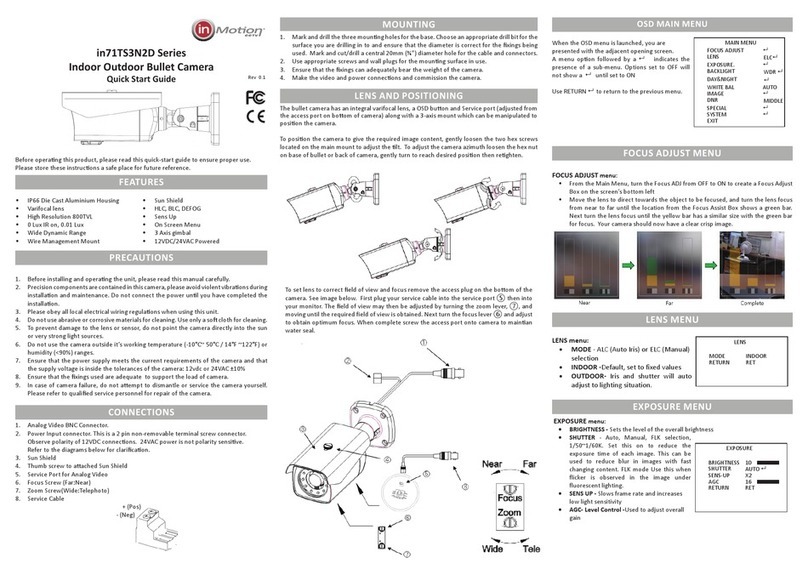
This manual suits for next models

11

Other InMotion Security Camera manuals

InMotion in51S2x2D Series User manual

InMotion

InMotion in51S2x2D Series User manual

InMotion in71TS3N2D Series User manual

InMotion

InMotion in71TS3N2D Series User manual

InMotion in4 S1P1L Series User manual

InMotion

InMotion in4 S1P1L Series User manual

InMotion inHS2 1L30 Series User manual

InMotion

InMotion inHS2 1L30 Series User manual

InMotion in51TS2x2D Series User manual

InMotion

InMotion in51TS2x2D Series User manual

InMotion in51S1P1D28V11 User manual

InMotion

InMotion in51S1P1D28V11 User manual

InMotion in10S1P1L User manual

InMotion

InMotion in10S1P1L User manual

InMotion in30S1x1L User manual

InMotion

InMotion in30S1x1L User manual

InMotion in51x1x1D Series User manual

InMotion

InMotion in51x1x1D Series User manual

InMotion in52S9x2D Series User manual

InMotion

InMotion in52S9x2D Series User manual

InMotion in52TS3N2D Series User manual

InMotion

InMotion in52TS3N2D Series User manual

InMotion in10S4x2L User manual

InMotion

InMotion in10S4x2L User manual

InMotion in10S2x2L User manual

InMotion

InMotion in10S2x2L User manual

InMotion in10S3P2L User manual

InMotion

InMotion in10S3P2L User manual

InMotion inTC Series User manual

InMotion

InMotion inTC Series User manual

InMotion in60x1x1D Series User manual

InMotion

InMotion in60x1x1D Series User manual

InMotion in21 Series User manual

InMotion

InMotion in21 Series User manual

InMotion in51S3P2D28V22 User manual

InMotion

InMotion in51S3P2D28V22 User manual

InMotion in52S8x2D Series User manual

InMotion

InMotion in52S8x2D Series User manual

InMotion in51S9P2D28V12 User manual

InMotion

InMotion in51S9P2D28V12 User manual

InMotion in30S1P1L25 User manual

InMotion

InMotion in30S1P1L25 User manual

Popular Security Camera manuals by other brands

Vicon Surveyor 282-20-02 Series Quick installation guide

Vicon

Vicon Surveyor 282-20-02 Series Quick installation guide

Foscam FI8910W Quick installation guide

Foscam

Foscam FI8910W Quick installation guide

Dahua HD Cube Network Camera quick start guide

Dahua

Dahua HD Cube Network Camera quick start guide

Brickcom Vandal Dome V2 Series user manual

Brickcom

Brickcom Vandal Dome V2 Series user manual

Axis PTZ user guide

Axis

Axis PTZ user guide

Samsung SCC-B5342 operating instructions

Samsung

Samsung SCC-B5342 operating instructions

Marmitek IP EYE ANYWHERE 21 - SOFTWARE ULTRAVIEW Advanced guide

Marmitek

Marmitek IP EYE ANYWHERE 21 - SOFTWARE ULTRAVIEW Advanced guide

Swann CoreCam user manual

Swann

Swann CoreCam user manual

Samsung SCB-3020 Specifications

Samsung

Samsung SCB-3020 Specifications

ACTi ACM-3011 Hardware user manual

ACTi

ACTi ACM-3011 Hardware user manual

Sanyo VDC-DP7584 - 1/4" Color CCD Vandal-Resistant Dome... Specifications

Sanyo

Sanyo VDC-DP7584 - 1/4" Color CCD Vandal-Resistant Dome... Specifications

Solwise H.264 IR-C1212H manual

Solwise

Solwise H.264 IR-C1212H manual

Speco HT-INTB1 user manual

Speco

Speco HT-INTB1 user manual

4xem 4X-IP7151 Specifications

4xem

4xem 4X-IP7151 Specifications

JAI TM-9730CL user manual

JAI

JAI TM-9730CL user manual

Sunell SN-IPV54/12UDN user manual

Sunell

Sunell SN-IPV54/12UDN user manual

Arec CI-T25H user manual

Arec

Arec CI-T25H user manual

Honeywell HEGS5300 user manual

Honeywell

Honeywell HEGS5300 user manual

manuals.online logo
manuals.online logoBrands
  • About & Mission
  • Contact us
  • Privacy Policy
  • Terms and Conditions

Copyright 2025 Manuals.Online. All Rights Reserved.