Inner Range SIFER Card Reader. Installation Manual. Revision 5.0 September. 2021.
Inner Range
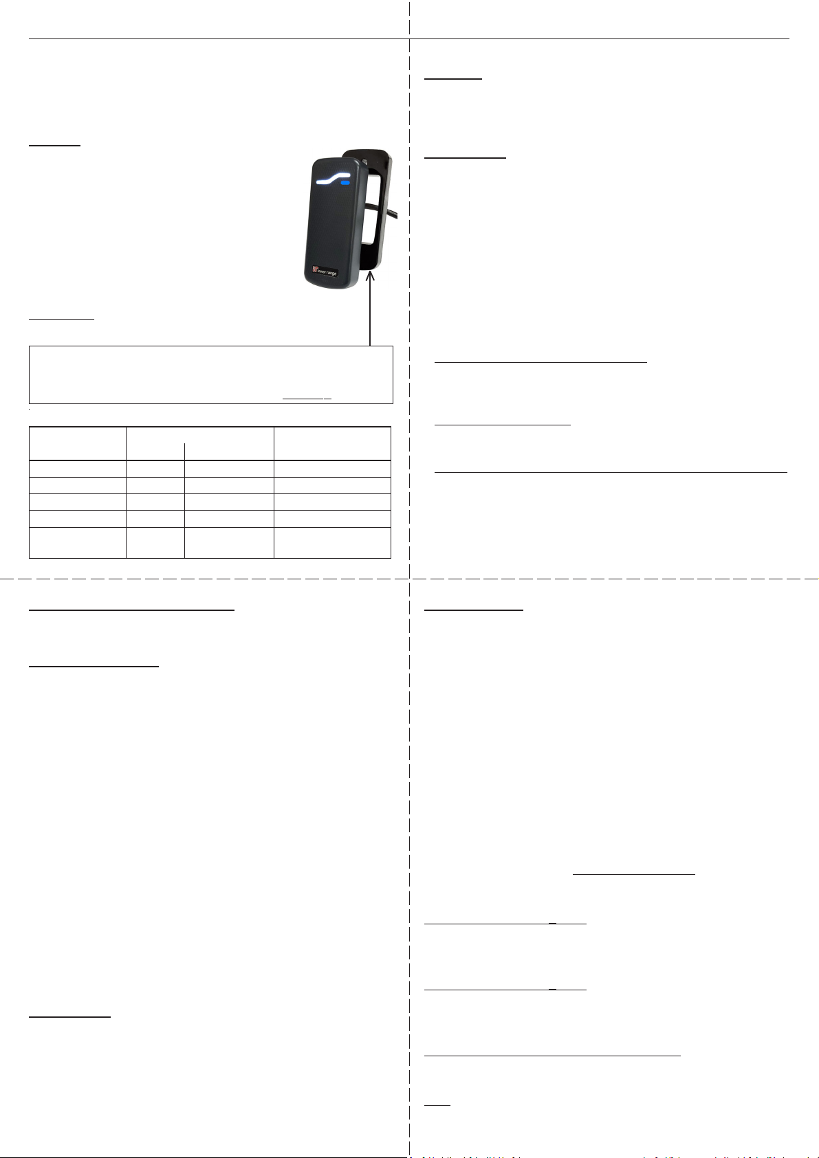
SIFER Smart Card Reader
P/N. 994720: Std / 994720MF: Multi-format
994723: SIFER Reader Mobile Access*
Features
- Suitable for narrow door frames or mullions.
- Optical tamper device.
- Configurable RGB LEDs and Beeper.
- Multi-format version reads CSN or UID data from other
13.56MHz formats. See Data Sheet.
- Connects to host Module via multi-drop RS485.
- Firmware updates over system wiring in Inner Range
systems. Latest firmware recommended.
- *Mobile Access version adds the ability to read secure
Inner Range Mobile Access credentials from compatible
iOS and Android devices.
Non-metallic mounting surface recommended.
See ‘Mounting Surface’ note on page 2.
UL Requirements (North America)
Refer to the Inner Range host LAN Module Installation manual for details of UL
regulatory requirements.
FCC (North America)
This device complies with Part 15 of the FCC Rules and Innovation, Science and
Economic Development Canada’s license-exempt RSS(s). Operation is subject to
the following two conditions:
1. This device may not cause interference; and
2. This device must accept any interference, including interference that may
cause undesired operation of the device.
Class B product:
This equipment has been tested and found to comply with the limits for a Class B
digital device, pursuant to Part 15 of the FCC Rules. These limits are designed to
provide reasonable protection against harmful interference in a residential
installation. This equipment generates, uses & can radiate radio frequency energy
and, if not installed and used in accordance with the instructions, may cause
harmful interference to radio communications. However, there is no guarantee
that interference will not occur in a particular installation. If this equipment does
cause harmful interference to radio or television reception, which can be
determined by turning the equipment off & on, the user is encouraged to try to
correct the interference by one or more of the following measures:
• Reorient or relocate the receiving antenna
• Increase the separation between the equipment and receiver
• Connect the equipment into an outlet on a circuit different from that to
which the receiver is connected
• Consult the dealer or an experienced radio/TV technician for help
Warning: Any changes or modifications not expressively approved by Inner Range
Pty Ltd could void the user's authority to operate this equipment
ISED Canada
L’émetteur/récepteur exempt de licence contenu dans le présent appareil est
conforme aux CNR d’Innovation, Sciences et Développement économique Canada
applicables aux appareils radio exempts de licence. L’exploitation est autorisée
aux deux conditions suivantes :
1. L’appareil ne doit pas produire de brouillage;
2. L’appareil doit accepter tout brouillage radioélectrique subi, même si le
brouillage est susceptible d’en compromettre le fonctionnement.
CAN ICES-3 (B)/NMB-3(B)
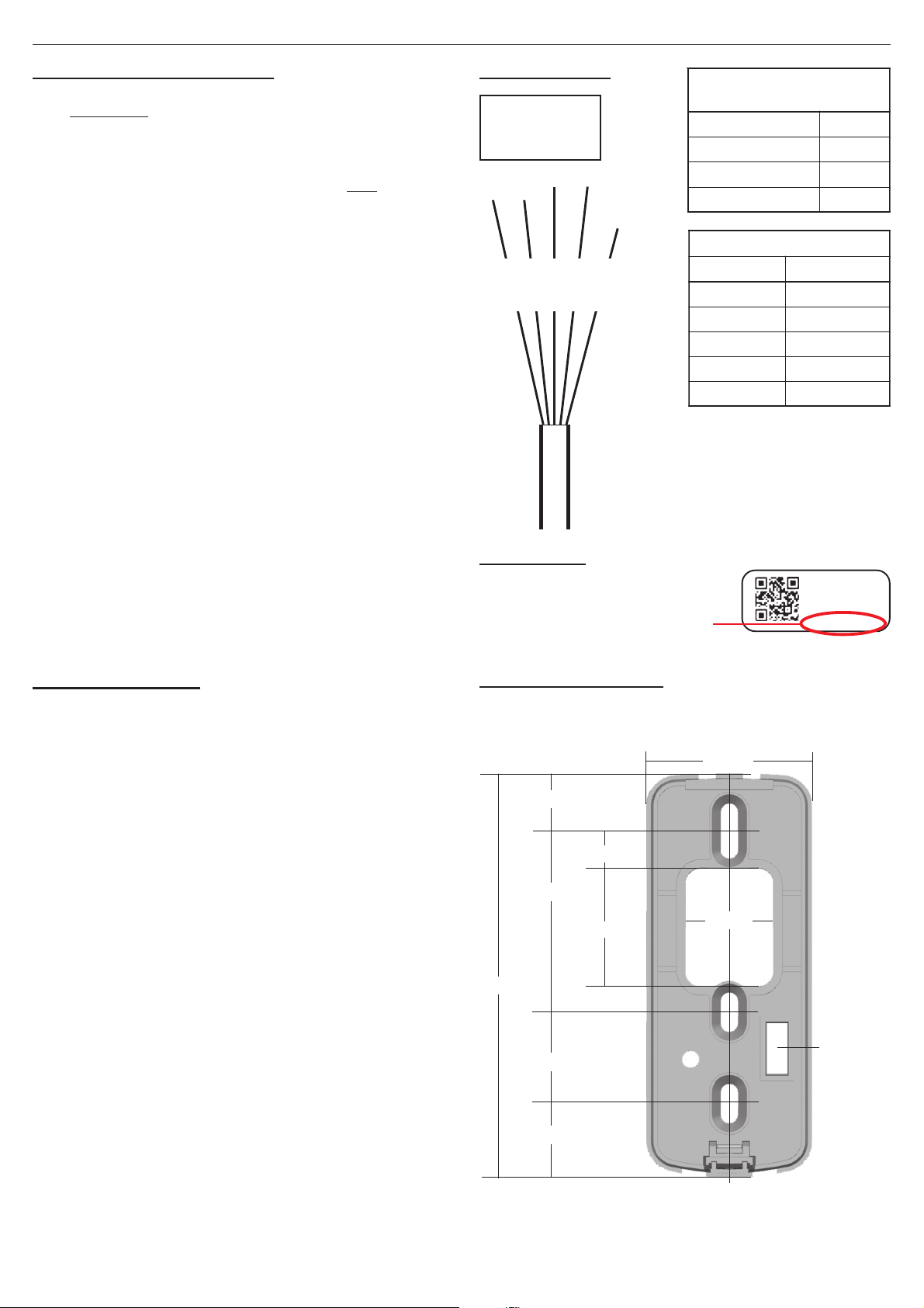
Extending Cable
See “Preliminary Installation Notes 3 & 4” on page 2.
The pigtail cable can be extended with twisted-pair multistrand
data cable. Pair 1 for Data A/B; Pair 2 for V+/0V. Shielded
cable provides additional noise immunity. RS485/RS422 data
cable, balanced data cable and multistrand UTP cable are
recommended. Specific recommendations are provided below.
Availability & approval for use may be dependent on your region.
Other cable types may be used. e.g. Non twisted-pair cable.
Refer to the Application Note; ‘SIFER READER CABLING
ALTERNATIVES’ or contact Technical Support for advice.
READER POWER: Remember to allow for voltage drop on V+/
0V over longer distances and/or when Readers are wired in a
daisy chain (multi-drop) configuration. Supply voltage drop on
the cable is approx. 17mV per metre, per Reader, using 7/0.2
(24AWG) cable and assuming each Reader draws 100mA.
OVERALL SHIELD (2Pair)
Tycab. DPF4702 or DCK4702 Belden. 9842
Electra. EAS7202P or EAS7302P Alpha. 6413
Roadworx. RW600224 Garland. MCP-2S
OVERALL SHIELD (3Pair)
Belden. 9843 Tycab. DPF6702
General Cable. B2003CS Garland. MCP-3S
Electra. EAS7203P Electra. EAS7303P
INDIVIDUALLYSHIELDED PAIRS (2 Pair)
Tycab. DQQ47025 Garland. MCP-2IS
Alpha. 2466C Belden. 8723
UTP
Garland UTPL5EMTP (4 Pair stranded UTP patch cable)
Parts List
- Installation manual. (This document)
- Reader body with integrated pigtail cable.
- Mounting plate and Countersunk screw.
Specifications
Operating Temp: -35°C to +65°C (-31°F to +149°F)
Ingress Protection: IP67
Physical dimensions. Height: 96 mm Width: 40 mm
Depth: 16.25 mm (26mm with Spacer)
Mounting plate: 91.6 mm (H) x 37.6 mm (W)
Power supply input: 11-14V DC <500mV ripple.
Current consumption: 75 - 100mA* typical. 150mA max.
*Depends on LED configuration.
V+/0V must only be connected to a power-limited circuit.
Maximum Cabling Distance using recommended cables.
Power (V+/0V). @100mA* per Reader.
To 1 Reader with 2-Pair 7/0.2 (24AWG) cable: 100m.
To 1 Reader with 2-Pair 14/0.2 (21AWG) cable: 200m.
To 2 Readers with 3-Pair (2 pairs for +V/0V) 100m.
Data (Data A/Data B/0V).
Access Module to furthest Reader: 1000m.
Total data cabling on one “RDR RS485” Port: 1000m.
Options for long cable runs &/or multiple Readers on the same run.
- Use heavier duty 2-pair cable.
- Use a spare pair or separate heavy duty fig. 8 cable for +V/0V.
- Use a separate local battery-backed power supply.
See “READER POWER” below for more details.
Page 1
ytilibitapmoC
tcudorPnoisreVerawmriFmuminiMsredaeRREFIS
FM/dtSsseccAeliboMeludoMrep
CAI/CSI0.4V?.12V)YLNOCAI(61
MALI0.2V?.?.3V61
MALS0.2V?.?.4V4
erawtfoSitirgetnI0.4V?.12Va/n
noitpecnI
rellortnoC
0.1V??Vtsumeraw'fREFIS(8
)retalro0.5.1Veb
Optional Spacer for metallic surfaces. Part Number:
- 999037 for SIFER Readers with Assembly Date Code 070820 (7th Aug. 2020)
or later. See ‘Barcode Label’ on page 2.
- 999033 for SIFER Readers with Assembly Date Code PRIOR TO 070820.