INNO IFS-15S User manual

Version:V1.00
IFS-15S
Master
User's Manual

Table of Content
PAGE 01
Introduction..................................................................................................................4
Chapter 1 Technical Specifications......................................................................................5
Applicable Fiber Type..........................................................................................................5
Splice Loss..........................................................................................................................5
Splice Mode..........................................................................................................................5
Heat Oven...........................................................................................................................5
Power Supply......................................................................................................................6
Dimensions and Weight.......................................................................................................6
Environment...............................................................................................................6
Other.................................................................................................................................6
Chapter 2 Installation..........................................................................................................7
Safety Warnings and Cautions...........................................................................................7
Safety Warnings...................................................................................................................7
Maintenance and External Care Precautions.....................................................................8
Transport and Storage Precautions....................................................................................8
Installation...................................................................................................................8
Unpacking the Splicer........................................................................................................8
IFS-15S and Accessories..................................................................................................9
Splicer Description and Functions....................................................................................10
Power Supply...................................................................................................................11
Two Ways of Power Supply..............................................................................................11
How to Charge the Battery................................................................................................12
How to Check Remaining Battery Capacity......................................................................12
Battery Refresh................................................................................................................13
Heat Oven........................................................................................................................13
Chapter 3 Basic Operation..............................................................................................14
How to Install Cleaving Table...........................................................................................14

PAGE 02
Turning Splicer "ON"......................................................................................................15
Adjust the Angle of LCD Monitor......................................................................................15
Adjust the Monitor Brightness.........................................................................................16
Preparing the Fibers........................................................................................................16
How to Make a Splice......................................................................................................17
Setting Fiber in the Fiber Holder......................................................................................17
Inspecting the Fibers.......................................................................................................18
Splice.............................................................................................................18
How to Protect the Splice................................................................................................18
Heating Procedure...........................................................................................................18
Chapter 4 Splice Programs.............................................................................................20
Displaying the Active Splice Program..............................................................................20
Selecting a Splicer Program...........................................................................................21
General Splicing Steps....................................................................................................22
Prefusion..........................................................................................................22
Fusion..........................................................................................................22
Splicing Process...............................................................................................................22
Standard Mode.................................................................................................................23
Chapter 5 Splice Option..................................................................................................24
Setting Parameters..........................................................................................................24
Chapter 6 Heater Mode...................................................................................................25
Selecting Heater Mode...................................................................................................25
Editing Heater Mode..........................................................................................................26
Heater Mode Parameters................................................................................................27
Chapter 7 Maintenance Menu.........................................................................................28
Replace Electrodes..........................................................................................................28
Replacement Procedure...................................................................................................28
User’s Manual
INNO Instrument, Inc.
IFS-15S
Master

PAGE 03
Stabilize Electrodes..........................................................................................................29
Operation Procedure........................................................................................................29
Diagnostic Test Function.................................................................................................29
Operation Procedure.......................................................................................................29
Dust Check......................................................................................................................30
Operation Procedure.......................................................................................................30
Motor Calibration..............................................................................................................30
Operation Procedure.......................................................................................................30
Arc Calibration..................................................................................................................30
Operation Procedure.......................................................................................................31
Electrode Setting.............................................................................................................31
Software Upgrading..........................................................................................................31
Chapter 8 Other Function & Utilities................................................................................32
Data Storage....................................................................................................................32
Display Splice Record......................................................................................................32
Clearing Splicing Results in Memory...............................................................................32
Cancel Data Storage........................................................................................................32
System Setting.................................................................................................................32
Change Monitor Position.................................................................................................33
Power Save......................................................................................................................34
System Information...........................................................................................................34
Appendix I........................................................................................................................35
Appendix II.......................................................................................................................36
Appendix III......................................................................................................................38
User’s Manual
INNO Instrument, Inc.
IFS-15S
Master
PAGE 04
Introduction
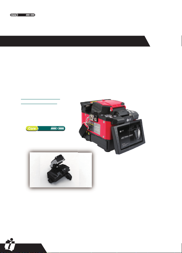
Thanks for choosing IFS-15S FTTx Master from INNO. The IFS-15S with
innovative design and exquisite manufacturing technology bring customers
unprecedented splicing experience.
New technology greatly reduce splicing and heating time. Advanced estimate
method and core alignment technique ensure the accuracy of splice loss
estimation. Its small size, compact design and reliable protection shell make it
suitable for any operating environment. Dynamic operation interface and automatic
splice mode give the customers great convenience.
For more information, please contact your local distributor or visit our web:
www.innoinstrument.com
www.innoinstrument.cn
Model: FH-K5
All-in-one Fiber Holder
This manual explains the features, specifications, operation, maintenance and
warnings about IFS-15S. The primary goal of this manual is to make the user as
familiar with the splicer as possible.
Important!
INNO Instrument recommends all users to read this manual carefully before
operating IFS-15S.
IFS-15S
Master
IFS-15S
Master
User’s Manual
INNO Instrument, Inc.
IFS-15S
Master

PAGE 05
Chapter 1-Technical Specifications
Applicable Fiber Type
Splice Loss
ζSM(ITU-TG.652) / MM(ITU-TG.651) / DS(ITU-TG.653) / NZDS(ITU-TG.655) /
ITU-TG.657
ζFiber count: Single
ζApplicable fibers:
0.25mm/0.9mm/2.0mm/2.4mm/3.0mm/Indoor cable
ζApplicable fiber diameter: Cladding diameter: 80~150μm, Coating diameter:
100~1000μm
Measured by cut-back method relevant to ITU-T standard:
ζSM:0.02dB
ζMM:0.01dB
ζDS:0.04dB
ζNZDS:0.04dB
ζG.657:0.02dB
Splice Mode
ζPreset 12 splice mode
ζInternal splice data storage: 2000
ζSplicing time: SM FAST mode: 7s
Heat Oven
ζApplicable protection sleeve: 40mm, 60mm
ζHeating time: 20~900s
ζCooling time: 0~ 180s
ζTypical heating time: 35s
ζHeater mode: 2 heater modes
ζHeat oven: IFS-15S Special Heat Oven(Detachable heater part for splice-on connector)
User’s Manual
INNO Instrument, Inc.
IFS-15S
Master

PAGE 06
Dimensions and Weight
Power Supply
ζInput power: AC 100~240V, 50~60HZ./ DC9~14V
ζLi-ion battery input: DC 11.1V . Completely charging time is about 3 hours.
ζSize: Length×Width×Height = 164mm×143mm×139mm
ζWeight: 2.1kg (battery included)/1.8kg
Environment
ζOperating condition: 0~5000m above sea level, 0~95% relative humidity, -10~50đ,
15m/s wind.
ζStorage condition: 0~95% relative humidity, -40~80đ; Battery: -20~30đfor long
time storage.
Other
ζViewing Method: two camera and 4.3 inch color LCD monitor (with high strength
protection shield on the top)
ζ300× magnification for single X or Y view. or 180× for both X and Y view.
ζTensile test: 1.96~ 2.25 N.
ζTerminals: USB2.0 for upgrading.
User’s Manual
INNO Instrument, Inc.
IFS-15S
Master

PAGE 07
Safety Warnings and Cautions
As IFS-15S is designed for fusion splicing silica glass optical fibers, it is very important that
the splicer should not be used for any other purpose. The splicer is a precision instrument
and must be handled with caution. Therefore, you must follow all safety rules and general
precautions in this manual. Any behavior that not follow the warnings and cautions will break
the safety standard about the fusion splicer and may result in electric shock, fire, and/or
serious injury. INNO will not take the responsibility for those results caused by misuse!
Chapter 2 - Installation
Safety Warnings
ŚNever operate the splicer in an environment where flammable liquids or vapors exist.
śDo not touch the electrodes when the splicer is on and power is supplied to the unit. The
electrodes generate high voltage and high temperatures that may cause a severe shock or burn.
③Do not disassemble or modify the splicer, AC adapter, battery or battery charger. In particular,
do not remove or bypass any electrical or mechanical device (e.g. a fuse or safety switch)
incorporated into the design and manufacture of this equipment. The equipment must be r
epaired or adjusted by an authorized technician or engineer. Unauthorized repair may result in
fire or electric shock.
④Properly connect the AC power cord to the splicer(inlet) and wall socket (outlet). When inserting
the AC plug, make sure there is no dust or dirt on the terminals. Engage by pressing the female
plug into the splicer (inlet) and the male plug into the wall socket (outlet) until both plugs are fully
seated. Incomplete engagement may cause fuming, electric shock, or equipment damage and
may result in injury, death, or fire.
⑤Never operate the splicer in an environment where flammable liquids or vapors exist. Risk of
dangerous fire or explosion could result from the splicer's electrical arc in such an environment.
Do not operate splicer near hot objects, in high temperature environments, in dusty/humid
atmospheres, or when water-condensation is present on the splicer. This may result in electric
shock, splicer malfunction, or poor splicing performance.
⑥Safety glasses should always be worn during fiber preparation and splicing operation. Fiber
fragments can be extremely dangerous if they come into contact with the eye, skin, or are
ingested.
⑦Disconnect the AC power cord from the AC adapter inlet or the wall socket (outlet) immediately
if user observes the following or if the splicer receives the following faults:
- Fumes, bad smell, noise, or over-heating occurs.
- Liquid or foreign matter falls into cabinet.
- Splicer is damaged or dropped.
If any of these faults occurs, ask our service centre for repair. Leaving the splicer in a damaged
state may cause equipment failure, electric shock, or fire and may result in injury or death.
⑧Do not use compressed gas or canned air to clean the splicer. They may contain flammable
materials that could ignite during the electrical discharge
⑨Use only the AC adapter designed for this splicer. Using an improper AC power source may
cause fuming, electric shock, or equipment damage and may result in injury, death, or fire.
Proper AC power source is AC 100~240v, 50~60Hz. Check the AC power source before use.
ţUse the supplied AC power cord. Do not place heavy objects on the AC power cord. Keep the
power cord away from heat source. Use of an improper cord or a damaged cord may cause
fuming, electric shock, or equipment damage and may result in injury, death, or fire.
Note: Only use specified electrodes for the fusion splicer. Select [Replace
Electrodes] option to replace electrodes. Turn the splicer off and disconnect the
AC power cord or remove battery before replacing electrodes. Discharging is
prohibited before the electrodes are placed as a pair.
User’s Manual
INNO Instrument, Inc.
IFS-15S
Master

PAGE 08
Maintenance and External Care Precautions
ŚAlways avoid using hard objects to clean V-grooves and electrodes.
śDo not use any chemical other than pure alcohol (99% or greater) to clean the
objective lens, V-groove, LEDs, LCD monitor, etc., of the splicer.
ŜUse a dry cloth to remove dust and dirt from the splicer.
ŝIf the outside of the splicer is dirty, plunge a soft cloth into diluted neutral washing
up liquid, wring out the cloth and clean. Dry the splicer with a dry cloth but DO
NOT use furniture polish or other cleaning agent.
ŞAlways follow the maintenance instructions in this manual.
Transport and Storage Precautions
ŚWhen the splicer is moved from cold to warm environment, you should allow the
splicer to warm up gradually. Otherwise, the condensation inside will be harmful for
the splicer.
śPack the fusion splicer for long time storage.
ŜKeep the splicer clean and dry.
ŝThe fusion splicer is precision adjusted and aligned. Always keep the slicer in its
carrying case to protect from damage and dirt. Put cushion package outside the
carry case for long distance transporting.
ŞAlways avoid leaving the splicer in direct sunlight or expose to excessive heat.
şDo not store the splicer in dusty/humid atmospheres. This may result in electric
shock, splicer malfunction, or poor splicing.
ŠKeep the humidity to a minimum level where the splicer is stored. The humidity
must not exceed 95%.
Installation
Important!
Please carefully follow the instructions below.
Unpacking the Splicer
Check the belt and hooks for damage before taking the splicer out. Lift the splicer
by the lifting belt as show below:
User’s Manual
INNO Instrument, Inc.
IFS-15S
Master

PAGE 09
IFS-15S and Accessories
Name Quantity
1.Fusion Splicer
2.High Precision Fiber Cleaver
3.Large-capacity Battery
4.Battery Charger and Power Cord
5.User's CD
6.Spare Electrodes
7.Carrying Case
8.Cooling Tray
9.All-in-one Fiber Holder
10.Kevlar Stripper
11.Auto Collector for Fiber Debris (option)
12.Cleaver Working Table (option)
13.AC Adapter(option)
14.Aerial Working Table (option)
15.Splice-on Connector Holder (option)
1
1
1
1
1
2
1
1
1
1
1
1
1
1
1
1 2 3 4 5
6 7 8 9
11 12 13
10
1514
User’s Manual
INNO Instrument, Inc.
IFS-15S
Master
PAGE 10
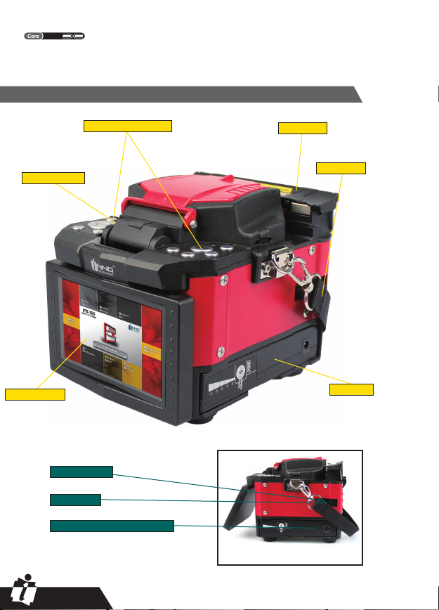
Splicer Description and Functions
Operating button Heat oven
Power ON/OFF
Lifting belt
LCD monitor Battery
USB port
Serial port
Power supply connector
Side
User’s Manual
INNO Instrument, Inc.
IFS-15S
Master

Power Supply
Two Ways of Power Supply
PAGE 11
Take out battery/AC Adapter
Release button
Inserting the
battery/AC Adapter
Inserting the battery into the
power unit dock until you hear "click".
Power off the splicer.
Press the release button,
and take out the battery.
The first way: battery operation
Insert the Battery into the power unit dock. Check and make sure the
remaining battery capacity is 20% or greater before operation.
Install the battery as below.
The second way: AC operation
Power the splicer by AC/DC adapter. Insert the AC/DC adapter into the
power unit dock in the same way with battery installation. Connect the
power cord to the AC/DC adapter as below.
Detaching the battery Inserting the battery
User’s Manual
INNO Instrument, Inc.
IFS-15S
Master

PAGE 12
Charging progress is indicated by five lit LEDs continuously sweeping from 20% to
100% on the battery indicator (see below).
As charging proceeds, one LED is lit when 20% charged. When it’s fully charged,
all five LEDs are lit (i.e. 100%).
Attaching Detaching
Note: 1. Check and make sure the remaining battery capacity is 20% or greater
before splicing. If the battery capacity is less than 20%, please use AC/DC
adapter to power the splicer.
2. Heat will be generated during the charging process. Do not stack the battery
on top of AC/DC adapter while charging.
How to Charge the Battery
How to Check Remaining Battery Capacity
You have two ways to check remaining battery capacity.
ŚIf the battery is connected to the slicer, then its charging level appears. The
power source which is used to charge the splicer is indicated by a special icon on
the top left corner of the monitor (see below)
<5%
<20%
<20-40%
<40-60%
<60-80%
<80-100%
Connect the battery charger to the battery.
If the splicer is powered through AC/DC adapter, there will be a sign on the top left
corner of the monitor. (see below)
ADAPTER
User’s Manual
INNO Instrument, Inc.
IFS-15S
Master

PAGE 13
śIf the battery is detaching from the splicer. Press "PUSH" button on the battery, battery
power is indicated by LEDs. As shown below:
100% 80% 60% 40% 20%
LED
Battery Refresh
In order to prevent the aging effect of
the battery, the battery need to be
refreshed periodically. Turn the splicer
on and discharging until it consume all
the battery capacity and the splicer turn
off automatically. Fully recharge the
battery and redo discharging.
2 1
Heat Oven
Open the heater lid
Cooling tray
User’s Manual
INNO Instrument, Inc.
IFS-15S
Master
PAGE 14
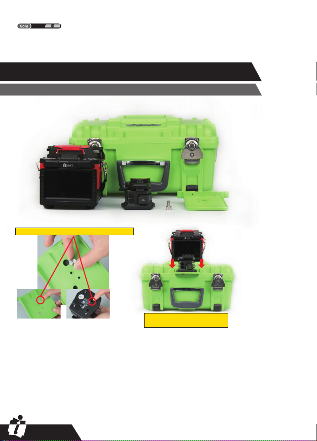
How to Install Cleaving Table
Chapter 3 - Basic Operation
Insert the cleaving table
into the slot on the carrying case.
Fix the cleaver on the Cleaving Table by matching screw.
User’s Manual
INNO Instrument, Inc.
IFS-15S
Master

PAGE 15
Turning Splicer "ON"
Press ON/OFF button on left operation panel. The ready screen is displayed after
the motors rest to their initial positions.
Adjust the Angle of LCD Monitor
Adjust the monitor angle to comfortably watch the screen.
User’s Manual
INNO Instrument, Inc.
IFS-15S
Master
PAGE 16
Adjust the Monitor Brightness
In the initial interface, press "ĭ" or "į"to change the monitor brightness until it is
clear enough.
Note: The LCD monitor of IFS-15S manufactured in a
quality-controlled factory environment. However, some black dots
may appear, or red/blue/green dots may remain on the screen. The
screen brightness may not appear uniform, depending on the viewing
angle. Note that these symptoms are not defects, but are natural on
LCDs.
Preparing the Fibers
3 steps for preparing fibers:
Step 1: Strip the fiber
①Remove at least 50mm of secondary coating
(valid for both tight and loose tube secondary
coating) with an appropriate stripper.
②Remove approximately 30mm of primary
coating with an appropriate stripper.
Step 2: Clean the fiber
Clean the bare fiber thoroughly with alcohol
impregnated gauze or lint-free tissue.
Step 3: Cleave the fiber
Cleave the fiber by high precision fiber cleaver.
In order to get excellent splice result, high
precision fiber cleaver should be used, such as
INNO VF- fiber cleaver. And the cleave length also
should be precisely controlled (shown below).
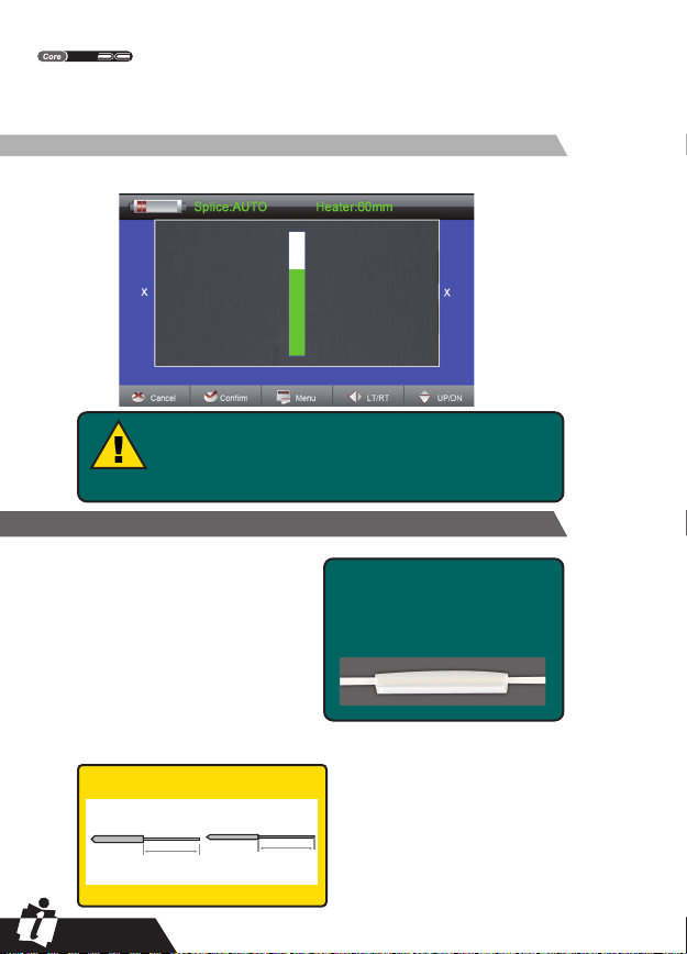
Note:
Always remember to slip a
heat-shrink sleeve onto either end
of the fibers at the beginning of
each fiber preparations.
Examples of cleaving length
≥10mm ≥10mm
Important!
From this point, you must be very
careful with the fibers to ensure that
they do not become dirty again.
- avoid putting them down on a dusty
working surface
- avoid waving them around in the air.
- check if the V-grooves are clean, if
not, wipe them clean
- check if the fiber clamps are clean, if
not, wipe them clean
Tight secondary coating
Primary coating
User’s Manual
INNO Instrument, Inc.
IFS-15S
Master
PAGE 17
How to Make a Splice
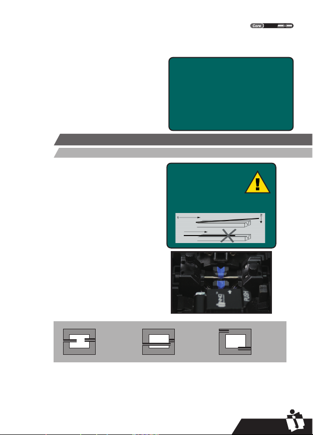
Setting Fiber in the Fiber Holder
Note:
Make sure to avoid sliding
the fibers along the
V-grooves, but rather
position them over the
V-grooves and then tilt
them down into place (see
picture below).
ŚOpen the wind shield.
śRaise the fiber clamps.
ŜPlace the fibers into V-grooves.
ŝMake sure the fiber ends are visible on
the monitor.
(4a) If the fiber ends are not visible, the
splicer will try to find them by moving the
fibers horizontally. The ends will be found
if the fibers are placed within the
mechanical movement range of the
horizontal motors.
(4b) If not, an error message will be
displayed. The splicer will not find fiber
ends that are placed above or below the
imaging area.
(4c) Normally, this should only happen if
the V-grooves or the fibers are dirty, or if
the splicer is not well adjusted.
ŞClamp the fiber in position by lowering both sets of fiber clamps.
şClose the safety shield.
As previously stated preparing the fibers
for splicing is one of the most important
factors in the splicing process and must
be carried out with the utmost care to
minimize splice loss. Therefore, consult
the check-list backwards to ensure that
these steps should be carried out.
Fiber preparation checklist
ȏThe correct V-grooves are selected (See
Chapter 7 "Maintenance ")
ȏThe fiber clamps and V-grooves are
clean
ȏA heat-shrink sleeve is in place
ȏThe fibers are stripped
ȏThe fibers are clean
ȏThe end-faces are well-cleaved
ȏThe cleaving lengths are correct
a.
Imaging area Fibre ends
visible on
the monitor.
b. Imaging area Fibre ends
outside
monitor.
c.
Imaging area
Fibre ends
above and
below
monitor, not
possible to
find
automatically.
User’s Manual
INNO Instrument, Inc.
IFS-15S
Master

PAGE 18
To change between Front
View and Back View, press
ĬorĮ.
If you find any defects as illustrated above, remove
the fibers and prepare again.
Before continuing with splicing, you should visually check the fibers in the monitor
to make sure they are clean and well-cleaved.
Note: The fibers are checked automatically when you press "Set"
button. The splicer automatically focuses the fibers and checks for
damage or dust particles.
Splice
ŚSelect the appropriate splicing mode. (described in detail in Chapter 4 "Splice
programs"- "Selecting a splice program")
śPress "SET" to start splicing.
Note: If the splicer set as "Auto Mode", the fibers splice once the
protection shield closed.
Heating Procedure
Inspecting the Fibers
How to Protect the Splice
After splicing, protect the joint by using a heat-shrink sleeve and the heat oven
which is mounted onto the splicer.
①Open the heat oven lid.
②Lift the left and right fiber clamps on the splicer.
Holding the heat-shrink tube (previously placed onto the fiber), lift the spliced fibers
and holding them taut, move the heat-shrink tube so that it is centered over the
splice point.
③Move both the fibers and the heat-shrink tube over to the heat oven and place
them in the oven clamps.
④Press "HEAT" to start. After heating, the led indicator will go out with buzzing.
Dust on fiber Tag
Chip Large cleave
angle
Front View
Back View
User’s Manual
INNO Instrument, Inc.
IFS-15S
Master

PAGE 19
Opening the heater lid Splice
Moving the fibers and protection
sleeve to the heat oven.
Heating Indicator Heat Button
User’s Manual
INNO Instrument, Inc.
IFS-15S
Master
Table of contents
Other INNO Industrial Equipment manuals


