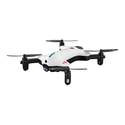
Innoflight Stellar X1000 User manual


© InnoFlight All Rights Reserved. 2016 2
Disclaimer
Thank you for choosing Stellar X1000 Mulcopter (Stellar). The Stellar mulcopter is a professional grade mul-
copter, and we are condent that you will enjoy the excellent handling and ying stability of both the Stellar
and the gimbal. Please read this document carefully and make sure that you have fully understood, and agreed
to our policies before using this product. By opening the packaging and using of this product, it is considered
that you have acknowledged, understood, and agreed to our policies and instrucons. InnoFlight is not liable
for any injury or loss of property during the use of this product.
Please make sure to follow all assembly procedures as instructed in this manual. Incorrect assembly could aect
the performance of the mulcopter, causing malfuncon, even crash during your ight. Also, please do not
aempt to alter any component or part of this mulcopter. InnoFlight is not liable for any damages or bodily
injuries that may occur from incorrect assembly or altering of parts. Duplicaon of any parts or components
without consent of InnoFlight is prohibited.
For any quesons or concerns during your assembly, please contact InnoFlight or your local dealer for technical
support. InnoFlight reserves the right to modify or edit this document without further noce. Please visit our
website - www.inf-drone.com periodically to keep the latest version of manuals, disclaimers and soware/rm-
ware updates.
About
The Stellar is designed to provide professional lmmakers or photographers a one of a kind aerial lming expe-
rience plaorm. You can let your creave imaginaon run free in a 3D space with unlimited arsc possibilies.
The Stellar is built with robust carbon ber body frame, foldable arms, and retractable landing gears allowing
the user high level of portability.
Our proprietary Jupiter JM-1 Flight Controller and the Mediate MA-1 3-axis stabilised camera gimbal will pro-
vide you with an intelligent and safe ight experience while allowing you to capture high resoluon images and
HD videos with ease.
Note: Camera is not included

© InnoFlight All Rights Reserved. 2016 2
Cauons
Please read this document carefully when operang the Stellar. Please make sure that you read and fully under-
stand the manuals, disclaimer, and noce of use before operang your Stellar. Failure to understand or ignoring
these instrucons may lead to failures and accidents which include but not limited to lost of control, system fail-
ures, and crash which may lead to collateral damage to properes and serious bodily injuries.
Please visit our website hp://www.inf-drone.com for assembly and system operaon tutorial videos. You may
also contact us directly at InnoFlight or your local dealer for any further quesons or concerns regarding the uses
of our product.
Pre-Flight Checks
1. Check that the baery level of the radio and the mulcopter are sucient for ight.
2. Ensure that there are no obstrucons which could prevent the motors, propellers and camera gimbal from
operang freely.
3. Check that there are no damages or deformaons to the propellers.
4. Perform magnetometer calibraon for your locaon.
5. Verify soware and rmware are updated to the correct versions.
6. Check that the area of operaon is suitable for safe ying.
7. Check that the weather condions are within your operang limits.
8. Ensure that you have understood all the ight modes and their associated switch posions.
Weather and Airspace Restricons
1. Some parts of the Stellar mulcopter are not water-proof - prolong exposure to water may cause malfunc-
on.
2. Avoid severe weather condions such as: rain, snow, and strong winds - wind speed not exceeding 10m/s.
3. Operaon at or near the North and South Polar areas may cause magnetometer malfuncon.
4. Only operate your mulcopter within visual line of sight, and keep clear of any building, obstacle, crowd of
people, and transportaon route.
5. Avoid ight operaon over water as emergency water landing will damage all electronic components.
6. Baery performance may vary from dierent manufacturers, operang environment, and temperature.
Please monitor the baery levels during charging and ight operaons on a regular basis.
7. Due to the large size of Stellar and powerful motors, please DO NOT operate this mulcopter indoor.
8. It is extremely important that you inspect all components to ensure the mulcopter operates normally aer
mishaps such as crashes or water ditching before you y the mulcopter again. If you have any quesons or
concerns, please contact InnoFlight or your local dealer for technical support.
Storage and Transportaon
1. Please keep the mulcopter out of children’s reach as the cables and small parts could cause entanglement,
suocaon, or accidental ingeson.
2. Please store the Stellar mulcopter in a dry and cool place.
3. In case of water exposure or immersion, please use so dry cloth to wipe away the moisture immediately
and DO NOT turn on unl the system is fully dried to avoid irreversible damages.
4. For daily cares, please use so dry cloth to wipe away the dust or stains. AVOID use of corrosive chemical
such as alcohol, acetone or any other chemical solvent
5. Please store the baery packs in dry cool places and away from direct sunlight or heat source to avoid dam-
aging the baery packs. We recommended storing temperature: 20 degree Celsius to 30 degree Celsius. DO
NOT store the baeries in places under -20 degree Celsius or over 45 degree Celsius. When in doubt please
check with your baery manufacturer for proper handling and storage recommendaons.
6. Pay close aenon to the baery level and usage. We recommend that you keep a logbook for all your
baery packs.

© InnoFlight All Rights Reserved. 2016 2
Flight Regulaon and No-Fly Zones
1. We DO NOT condone any illegal operaons of the Stellar mulcopter such as but not limited to the follow-
ing:
• Flying in restricted airspaces, airports, and aircra ying routes.
• Flying near other aircras such as airliners during their takeo and landing operaons.
• Flying over populated areas and large crowd of people such as cies, arenas, stadiums, exhibion halls
and any other large assembly of people.
• Flying over designated no-y zones.
• Flying in above restricted and assigned altudes.
• Intenonally ying beyond visual line of sight.
• Carrying illegal explosive with or without intenon to drop from mulcopter.
2. Ensure that your ight plan is recognized and approved by local administrave oces. If unsure, please
consult with local law enforcement oces and relevant authories for details. For commercial purposes,
please be sure such act is complied to local laws and regulaons.
3. DO NOT conduct ight operaon using sensors with intenon to monitor and probe others’ privacy with
this product.
4. Be sure that the photographs and/or video footages taken with this product is not violang intellectual
property rights or copyrights of countries, organizaons or persons.
5. No-Fly Zones include but are not limited to: airports, country borders, cies, sensive areas, governmental
oces, power plants, jails, water reservoirs, and military bases. Please make sure you observe local laws,
rules, regulaons, and seek proper permissions and authorisaons when choosing locaon for your ight
operaons.
6. Please be noted that you would not be able to set waypoints within No-Fly Zones.
7. Please do not exceed the altude limitaon specied or authorised by your local laws and regulaons.
Flight Operaon Guidelines
1. Stellar mulcopter is not a toy. Improper operaons of the mulcopter can cause serious injury to yourself
and other people. You should choose an open space, and away from crowds of people to operate the Stellar
mulcopter.
2. DO NOT y near main roads, airports, railways, or any transportaon routes
3. DO NOT y near high voltage power line as the electromagnec radiaon may create interference.
4. DO NOT y in low visibility condions such as in foggy or rainy weather to avoid accidents caused by poor
visibility or electronic equipment failures.
5. DO NOT y in strong winds and excessively high altude environment. Strong winds could aect the po-
sioning and atude control funconality of the mulcopter. Excessive high altude operaons could re-
duce the performance of the mulcopter.
6. You MUST operate the Stellar Mulcopter in accordance with your federal and local rules of law.
7. You MUST strictly observe rules and regulaons set out by your individual country’s civil aviaon governing
body while operang the Stellar Mulcopter.
8. Please read the operang manual carefully before ying your mulcopter.
9. Extra safety precauons must be taken while operang and working around rotang propellers to prevent
accidents and serious personal injuries.
10. Only operate your mulcopter within visual line of sight.
11. DO NOT use cellular phones when ying. Electromagnec radiaon could interrupt the remote control
signal.
12. Please pay close aenon to your baery level when ying . You may not be able to return safely when the
baery is too low.
13. Always turn on the power of your radio before turning on your mulcopter.
14. Always turn the mulcopter power to o rst before turning o the radio at the end of each ight.
15. Always disarm the motors of your mulcopter immediately aer landing to prevent inadvertent take-o.
16. DO NOT disarm the motors while in ight as this will cause the mulcopter to crash.

© InnoFlight All Rights Reserved. 2016 2
In the Box
Stellar Main Fuselage Assembly x 1 Landing Gear x 2
Baery Tray Assembly x 2 Propeller set x 10
Top Hatch x 1 Accessories Package x 1
Doubled sided tape x 2
3M Velcro Strips x 2
Baery straps x 4
Hex Screwdriver x 1
XT-90 Connectors x 2
USB Cable

© InnoFlight All Rights Reserved. 2016 2
Assembly Instrucons
Please read and follow the installaon and setup instrucon in the steps outlined below.
Extra care must be taken during setup and tesng - the rotang propellers may cause subtanal damage and
serious injury.
Motor Arms Folding and Unfolding Procedures
The four foldable motor arms on the Stellar mulcopter are factory pre-installed for ease of transport. To unfold
the arms please follow the below procedures:
1. Press the top and boom spring loaded locking buons as indicated by arrows
2. Gently unfold the rear motor arm unl the top and boom locking buons click into their respecve holes
on the top and boom centre frame plates.
3. Repeat steps for the other rear motor arm
4. Repeat steps for the two front motor arms while unfolding them from their retracted posions on the cen-
tre frame
* Visually inspect to ensure that all locking buons are secured both at the top and the boom of the centre
frame.

© InnoFlight All Rights Reserved. 2016 2
Moung the Landing Gears
1. Insert one landing gear leg into each retractable unit on the right and le side of the center frame.
2. Secure the landing gear legs to the retractable units with M3 x 18 bolts. Please note the direcon of the
bolts for right and le side.
3. Check the two pre-installed retract servo cables are sercured.
* Visually line up the pre-drill holes on each landing gear to the holes on the retract units.
* Install one M3 x 18 Socket Cap Bolt for each landing gear using thread lock compound as requires
M3 x 18mm

© InnoFlight All Rights Reserved. 2016 2
RC Console Setup
To take advantage of all the features included in the Jupiter JM-1 autopilot please choose R/C system capable
of the following funcons.
• Assign sck control for Aileron, Elevator, Throle, and Rudder
• One 3-posion switch for switching between dierent ight modes
• One 2-posion switch for acvang Return to Launch (RTL) funcon
• One 3-posion switch for switching between dierent Augmented Control Modes (ACM).
• One 2-posion switch for controlling retractable landing gear
We recommend that you create a new model in your radio and set all channel end points to ±100% and deac-
vate Dual Rates and Exponenal Curves
RC Reciever Installaon and Binding
The Stellar comes pre-installed with the InnoFlight state of the art Jupiter JM-1 ight controller. The Jupiter JM-1
ight controller is fully compable with Futaba ™ S.Bus, Spektrum™ DSM2/DSMX, JR™ XBus, Graupner™, and
Je™.
You may ax receiver in the locaon shown below using the supplied double sided adhesive tape, and plug in
the Sum Bus cable provided.
The Jupiter autopilot suports up to two satellite receivers. Please plug the satellite receivers in to Sat.1 and Sat.2
port on the Jupiter JM-1 autopilot using the satellite cables supplied by the manufacturer.
Sat.1 Sat.2
Receiver Locaon

© InnoFlight All Rights Reserved. 2016 2
Propeller Installaon
1. Use two supplied M3 x 8mm stainless steel step bolts to install propeller blades as shown in drawing.
2. Apply medium thread locking compound to the thread of the bolts.
3. Tighten bolts to 0.4Nm of torque.
M3 x 8mm step bolt
Propeller Orientaons
It’s important to note the propeller orientaons as per drawing below when you are installing propellers.. The
Black arrows indicate top propellers and the Red arrows indicate the boom propellers.

© InnoFlight All Rights Reserved. 2016 2
Baery Tray Installaon
Your Stellar mulcopter is equipped with quick release baery trays made of high quality carbon bre plates
and CNC aluminium locking/release mechanism.
1. To install baery, slide the baery and tray onto the rail mounng system installed underneath the Stellar
mulcopter. Be sure to push the baery rmly unl the baery connector and locking mechanism are fully
engaged.
2. To remove baery, pull rmly on the latching mechanism and slide baery out.
Latching Mechanism
* For best preformancce, we suggest you use 6S lipo baery with capacies ranging from 10,000mAh to
22,000mAh at 15C to 25C

© InnoFlight All Rights Reserved. 2016 2
Mounng the Meditate Gimbal
Ax the Connext video transmier module to the top plate of the Meditate gimbal as shown using supplied
double sided tape.
Panasonic LumixG GH4 camera is shown as an example and is not included.
Mount the gimbal assembly and the enre so mount system to the boom of the mulcopter frame using 8
supplied M2.5 x 8mm bolts as shown below. Use thread locking compound as required
Meditate Gimbal

© InnoFlight All Rights Reserved. 2016 2
Meditate Gimbal Quick Release
The Meditate gimbal is equipped with a quick release system for your convenience.
1. To release/install the gimbal you only need to loosen the two M3 x 12mm bolts
2. Unplug the GCU interface cable from the boom of the payload mounng plate
3. Slide the gimbal assembly out.
Starng/Stopping the Motors
The start and stop (arming) the motors, please perform any one of the following control sck combinaons.
• When motor is armed, the Green, Blue, and white LED will blink rapidly for one second
• When motor is disarmed, the Green, Blue, and white LED will blink slowly for one second
Please also note the following condions:
In Manual Mode - when the motors are armed and the throle sck remains below the mid-point for more than
5 seconds, the motors will turn OFF. If the throle sck is raised above the mid-point within 5 seconds then the
motors will remain ON.
When landing in GPS/Atude Mode - If the throle sck is kept below -90% then the motors will turn OFF af-
ter 5 seconds however for added safety we suggest you always manually disarm the motors immediately aer
landing.

© InnoFlight All Rights Reserved. 2016 2
Magnetometer Calibraon
The magnetometer is the key module in Jupiter JM-1 allowing the mulcopter to maintain precise heading hold.
However, it is also very vulnerable to the changes in surrounding magnec eld.
We highly recommend that you perform magnetormeter calibraon the rst ight in. When ying without
calibrang the compass, the mulcopter may not be able to hold proper heading and poor GPS hold soluon.
Please calibrate the magnetormeter in open outdoors space and stay away from reinforced concrete, and avoid
close proximity of metal or magnec objects such as keys, or mobile phones.
Please calibrate the compass periodically or whenever you are operang the mulcopter in a new locaon in
order to ensure its precision.
Here are some situtaons that may require calibraon of the magnetometer:
1. Change of ying locaon
2. Mechanical alternaon - when the mounng posion of GPS-Compass is changed
3. When mechanical structure is altered
4. Driing of heading and GPS
Calibraon Procedures:
1. Turn on the mulcopter by pulling out the arming plug
2. Flip the “Flight Mode” switch back-and-forth for 3 mes in two seconds
3. Blue LED light will stay ON
4. Rotate the mulcopter for 360° horizontally
5. Blue and Green LED will stay ON
6. Set the nose poinng up/down and rotate the mulcopter for 360° vercally
7. Green LED will blink when completed
8. Reset power to the mulcopter

© InnoFlight All Rights Reserved. 2016 2
Appendix
LED Status Indicator
The Stellar is equiped with a four colour LED indicator module aached to the right retractable landing gear
actuator. It is very important that you fully understand the LED colour combinaons and what they mean while
operang the mulcopter.
On inial power up, you should see all LED lights turned “ON” momentarily then one colour LED indicaon de-
pending on corresponding ight mode as per LED matrix below.
Baery Level Indicator
The Baery Level Indicator light panel is located at the rear of the frame. You may check the baery level at
anyme when there is a baery installed on the airframe simply by pressing the baery checker buon.
When the arming plug is removed the light panel will turn on to give you baery level indicaons. Please refer
to the matrix below.
Baery Check Buon
4.09V - 4.2V Baery is fully charged
3.97V - 4.08V Normal operaon
3.85V - 3.96V Recommended rst stage warning
3.73V - 3.84V Return to Launch
3.6V - 3.72V Land immediately
Less than 3.59V Baery is malfunconing or damaged
LED Indicaon Table
All LED light up and stay ON No RC signal or System Malfuncon
Red LED Flashing Rapidly Low Main Baery Voltage
Flashing Blue No GPS (in Atude Flight Mode)
Solid Blue No GPS (in GPS Flight Mode)
Flashing Green GPS is Ready (in Atude Flight Mode)
Solid Green GPS is Ready (in GPS Flight Mode)
Blue and Green Flashing RTL Mode Acvated
White LED Augmented Control Mode - Refer to JM-1 Manual
Red LED Stay ON GPS or Magnetometer Malfuncon - Refer to JM-1 Manual

© InnoFlight All Rights Reserved. 2016 2
Airframe Specicaons
Frame
Type X8 Coaxial Setup with Foldable Arms
Diameter 800mm
Weight (without gimbal and baery) 4284g
Landing Gear Dimensions 480mm (H), 550mm (W), 420mm (L)
Motor
Diameter 52mm
KV Value 380kV
Maximum Rated Power 550W
ESC
Maximum Output Power 750W
Working Current 10A
Maximum Current 30A
Operang Voltage 11 - 25VDC, 3S to 6S Lipo Typical
PWM Frequency 32kHz
Signal Frequency 400Hz
Propeller (1554/1554R)
Material High temperature and moisture resistant bre reinforced plasc
Size 15 x 5.4 inch
Performance
Maximum Take-o Weight 10kg
Baery 6S Lipo at 25C. 10,000mAh to 22,000mAh
Endurance up to 15 minutes on 16,000mAh (tested with GH4 and MA1 gimbal)
Maximum Output Power 5000W
Maximum Wind 12m/s
Operang Temperature -10°C to +40°C
ESC Sounds
ESC State Sound
Inialising 1 2 3
Lipo Cell Count B B B B B B (one beep per cell. Ex. 6 beeps for 6S)
Inialisaon Complete BB BB BB

© InnoFlight All Rights Reserved. 2016 2
Jupiter JM-1 Autopilot Specicaons
Features
Flight Control Modes Manual, Atude, GPS Hold
Enhanced Lost Comm Protecon Auto Return to Launch, Auto Hover
Augmented Control Modes Point of Interest, Steer Orientaon, Home Orientaon
Supported R/C Futaba ™ S-Bus, Spektrum™ DSM2/DSMX, JR™ XBus, Graupner™, and
Je™
Conguraon and Setup Link USB and built in Bluetooth
Data Logger Built in Data Logger
Compable Plaorm I4, X4, I6, X6, V6, I8, V8, and X8
Electrical
Working Voltage 4.5 - 8.5V DC
Power 3W or 0.5A at 5V typical
Working Temperature -10°C to 60°C
Physical Characterisc
Main Controller 60mm x 35mm x 20mm at 54g
GPS/Magnetometer 40mm diameter x 10mm at 15g
Power Distribuon Board 74mm x 55mm x 14mm at 78g
Flight Controller Performance
Vercal Tolerance (GPS) ± 0.5m
Horizontal Tolerance ± 1.5m
Maximum Yaw Angular Velocity 150°/s
Maximum Pitch Angle ± 30°
Maximum Ascent and Descent Velocity ± 6m/s

© InnoFlight All Rights Reserved. 2016 2
Part List
We have packaged replacement parts into packs for your convenience should you have the need for repair or
replacing of worn out parts. Please refer to the replacement part tables when ordering part packs.
To be connued...

© InnoFlight All Rights Reserved. 2016 2
FEDERAL COMMUNICATIONS COMMISSION INTERFERENCE STATEMENT
This equipment has been tested and found to comply with the limits for a Class B digital device, pursuant to part
15 of the FCC Rules. These limits are designed to provide reasonable protecon against harmful interference in
a residenal installaon. This equipment generates, uses and can radiate radio frequency energy and, if not in-
stalled and used in accordance with the instrucons, may cause harmful interference to radio communicaons.
However, there is no guarantee that interference will not occur in a parcular installaon. If this equipment does
cause harmful interference to radio or television recepon, which can be determined by turning the equipment
o and on, the user is encouraged to try to correct the interference by one or more of the following measures:
-Reorient or relocate the receiving antenna.
-Increase the separaon between the equipment and receiver.
-Connect the equipment into an outlet on a circuit dierent from that to which the receiver is connected.
-Consult the dealer or an experienced radio/ TV technician for help.
CAUTION:
Any changes or modicaons not expressly approved by the grantee of this device could void the user’s author-
ity to operate the equipment.
This device complies with Part 15 of the FCC Rules. Operaon is subject to the following two condions: (1) this
device may not cause harmful interference, and (2) this device must accept any interference received, including
interference that may cause undesired operaon.
RF exposure warning:
This equipment must be installed and operated in accordance with provided instrucons and the antenna(s)
used for this transmier must be installed to provide a separaon distance of at least 20 cm from all persons
and must not be co-located or operang in conjuncon with any other antenna or transmier. End-users and
installers must be provide with antenna installaon instrucons and transmier operang condions for sas-
fying RF exposure compliance.
NCC STATEMENT
經型式認證合格之低功率射頻電機,非經許可,公司、商號或使用者均不得擅自變更頻率、加大功率
或變更原設計之特性及功能。
低功率射頻電機之使用不得影響飛航安全及干擾合法通信;經發現有干擾現象時,應立即停用,並改
善至無干擾時方得繼續使用。
前項合法通信,指依電信法規定作業之無線電通信。低功率射頻電機須忍受合法通信或工業、科學及
醫療用電波輻射性電機設備之干擾。
本產品內含射頻模組,其NCC刑事認證號碼為: CCAH15LP1880T8
Table of contents
Other Innoflight Drone manuals


