Innohome SSA15 Manual

• Must be installed by an authorized electrician.
• Asennuksen saa suorittaa vain valtuutettu sähköasentaja.
• Måste installeras av en auktoriserad elektriker.
Installation Instructions &
Operating Instructions
SMART SMOKE ALARM
Asennusohje &
Käyttöohje
ÄLYPALOVAROITIN
Installationsinstruktioner &
Bruksanvisning
SMART RÖKLARM

3
INSTALLATION
INSTRUCTIONS
CONNECT THE SMART SMOKE ALARM SSA
... 3
ELECTRICAL PLANNING.......................................... 4
RESIDUAL CURRENT DEVICES RCDs................ 6
POSSIBLE INSTALLATION FAULTS ....................... 6
OPERATING
INSTRUCTIONS
1. GENERAL CONSIDERATIONS........................ 7
2. INDICATION LED............................................... 8
3. MAINTENANCE AND FUNCTION TEST...... 9
4. IN CASE OF EMERGENCY CUT-OFF ............ 10
5. TROUBLESHOOTING........................................ 11
6. LIMITATIONS OF THE SYSTEM...................... 12
7. MAINTENANCE.................................................. 12
8. WARRANTY......................................................... 13
9. DISPOSAL............................................................ 13
10. MAINTENANCE DOCUMENT...................... 14
EU DECLARATION OF CONFORMITY.............. 15
TECHNICAL SPECIFICATIONS............................ 15
The actual product may
vary from the image above

3
CONNECT THE SMART SMOKE ALARM (SSA)
Detailed installation instructions will be provided with the alarm unit. The diagram below describes correct
wiring of the Smart Smoke Alarm.
L
N
PE
230 V~
8 mm
Connect to the
alarm unit
INSTALLATION INSTRUCTIONS

4 5
COMPARTMENTATION OF THE AREAS
Comp. 2
Comp. 1
SSA
Comp. 1
SSASSA
SSA
Comp. 2
RCD
RCD
RCD
30mA
RCD
30mA
ELECTRICAL PLANNING
The Smart Smoke Alarms are connected to the fixed mains voltage supply of the building. Because
of this it would be reasonable to take into account how to get the maximum benefit from the
alarms in the planning phase. How should the electrical groups be grouped? Will the heating
appliances be connected to the system circuit?
In the planning phase, reserving sufficient space in the electrical panel for the residual current
devices (RCDs) included in the system will facilitate the installation.
Most important in the planning phase is to take into account that the Smart Smoke Alarm unit
must receive continuous electrical supply. Therefore, it must be ensured that the device will not be
connected erroneously behind any switches.
NEWLY CONSTRUCTED BUILDINGS
In a newly constructed building, where the interior wiring of the installation is done according to the
TN-S system, the locations of the alarms must be considered in the planning phase. In the electrical
planning one must take into consideration the compartmentation of the areas.
Separating the groups into compartments can limit the cutting of electricity only to the area where
the alarm is set o. Below, an example of compartmentation.

5
Fluorescent tubes are potential causes of fire, but at the time of the alarm is also good to be able to
see inside the room. Below, the electrical grouping has been done in such a way that the lamps will
not turn o when the alarm is set o.
When installing the Smart Smoke Alarms in buildings under renovation, it might be necessary
to add wiring. In the electrical wiring older than the TN-C system, it is necessary to install PE
conductors between the RCDs and the Smart Smoke Alarm units.
SSA CONNECTION AND A TN-C SYSTEM
In grounded outlets those set to zero must
be dismantled and a PE conductor added
RCD located in the
electrical panel Fire and
people
protection
Ungrounded
outlets are changed
to grounded
outlets
The RCD will be installed in the electrical
panel or in a separate box nearby.
A PE conductor is added in the circuit.
SSA in wall surface installation.
SSA
PEN-L PE-N-L
N-L
PE-N-L
RCD
30mA RCD
30mA SSA
GROUPS OF LIGHTS AND OUTLETS
Room 1
SSA
SSA
Room 2
RCD
RCD
RCD
RCD
30mA
RCD
30mA
RCD
30mA
INSTALLATION INSTRUCTIONS

6
POSSIBLE INSTALLATION FAULTS
• Verify that RCDs trip when the test button is pressed. If not, the RCD is faulty or wrongly installed and therefore
SSA cannot work either
• Verify that L conductor and N conductor are properly connected through the RCD
• Verify the continuity of the N and PE conductors and that they are with low resistance (less than 2–3 ohms depending
on the local regulations)
• Verify that the SSA is connected so that its operation is not depending on any external switch like light switch
• The zero setting has been used in the electrical circuit (e.g., in the outlet socket)
• The N conductor behind the RCD is connected to another N conductor of another electrical circuit
• The interference suppression circuit of an electrical device produces a current that constantly exceeds the limit for RCD
tripping current
• The PE conductor is incorrectly connected
RESIDUAL CURRENT DEVICES (RCDs)
By selecting a residual current device (hereafter called RCD) one must take into account that the
Smart Smoke Alarm unit produces a fault current with a maximum of 50 mA in the main supply.
Nominal fault current for the RCDs to trip is 30 mA, hence the system also provides protection
against electric shocks. The electric shock that is produced is at the most 30 mA, which is not dan-
gerous for a person with a normal physical condition.
When selecting a RCD one must take into account what type of charge is going to be connected in
the protected circuit. The RCD connected to the Smart Smoke Alarms must be of the type A or type
AC. The type A RCD functions with alternate or direct current in the pulse mode, and the AC type
functions only with alternate current. Using a type A RCD is recommended, because in this way the
system also functions as a type of controller of the electrical device’s condition. If the RCD seems to
trip too easily, there might be too many appliances within the group, or there is a single faulty
appliance. It may also be due to a failure within the installation; see possible installation faults
below. In the Smart Smoke Alarms, the RCD must be installed in the electrical panel of the group
so that the switch’s test button is easily accessible. The RCD must be marked so that the user clearly
understands which RCD relates to which Smart Smoke Alarm.
7

USER INSTRUCTIONS
The Innohome Smart Smoke Alarm (SSA) helps to protect your family and property against res
caused by electrical appliances. Such res may be caused by faulty electrical equipment or by
careless use. In addition to re protection, the Smart Smoke Alarm also provides protection against
electric shock. As the SSA identies the danger, in addition to an acoustic alarm it raises, it makes
the power to cut o from the power mains supply. The power cut-o is enabled by imitating the
fault current pulse, which makes the standard residual current devices (RCDs) located on the main
electrical panel to trip and cut o the electrical supply to a number of appliances.
1. GENERAL CONSIDERATIONS
The Smart Smoke Alarm is powered by mains voltage supply, and it must be installed by an autho-
rized electrician only. The green LED of the alarm unit indicates that the mains supply is connected,
and the product is operational.
7
• Maintenance and testing of the Smart Smoke Alarm should be carried out monthly.
• The detector type and model of your Smart Smoke Alarm is marked on the product package.
• The alarm unit will beep every 30 seconds for low back-up battery. As this occurs, the battery
shall be replaced without any delay.
• The Smart Smoke Alarm is for indoor use only, and its operational temperature range is between
5 and 40 ºC. Its working life is approximately 10 years, after which it should be replaced.
• The used Smart Smoke Alarm should be recycled according to the local regulation and practices.
Do not dispose it with domestic waste.
• When the alarm sounds, check for the cause (defective electrical appliance or wiring), take
appropriate measures and then restore the power from the residual current device (RCD).
READ BEFORE USE:
OPERATING INSTRUCTIONS

2. INDICATION LED
When the mains supply is connected, the
indication LED will remain steadily green and
the red LED will ash occasionally to show the
alarm is operating correctly. In the alarm state,
the red LED ashes rapidly and the alarm unit
emits an audible alarm.
The alarm is set o when the alarm unit detects
the continuous presence of smoke, or, in the
case of a heat detector, when the temperature
exceeds the pre-set limit value. The alarms
return to the standby state when smoke has
disappeared or when the temperature has
dropped below the pre-set level.
Note:
Very dense smoke may disable temporarily the
hush function, and a constant alarm will sound.
Warning:
Before using the hush function, check the
cause of the smoke and make sure the situation
is safe. If you wish to use the hush function on
the heat alarm, be very careful to make sure
you know the cause of the alarm before you
do so.
89
Indication LED/
Test button

3. MAINTENANCE AND
FUNCTION TEST
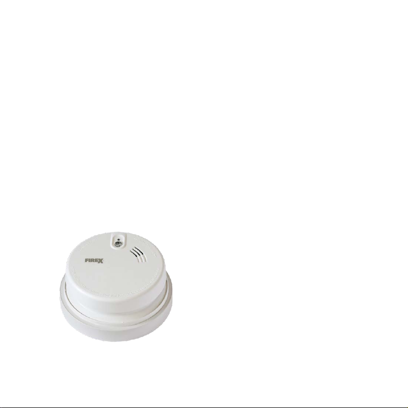
It is recommended to perform a function test
for the Smart Smoke Alarm monthly. The function
test is done by pressing the test button
on the alarm unit. If the RCD trips and the
power to the electrical appliances within the
group is cut o, the Smart Smoke Alarm is fully
operational. After performing the function test,
it is important to restore the power by resetting
the protection switch of the RCD. If you do not
know where the electrical panel or the RCDs
are located, contact the administrator of your
building or the installing electrician.
The gure shows a typical RCD. The device in
your home may not be identical with the
device on the left. The RCD test button is
normally marked with the letter“T”.
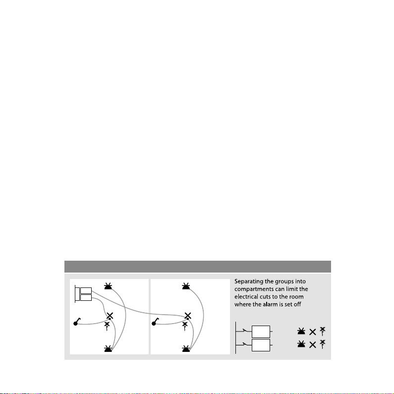
If the Smart Smoke Alarm has been installed in
accordance with the instructions, the numbers
on the protection switches will match those of
the alarm units. The numbers are marked in the
maintenance document.
If the RCD does not trip, see the instructions in
Section 5.
The Smart Smoke Alarm should be maintained
on a regular basis according to the alarm unit’s
own instructions.
The working life of the alarm battery can vary
depending on the type of batteries used. If the
battery needs replacing, a beep will sound at
intervals of 30 seconds. When this occurs, the
battery shall be replaced without delay.
The working life of the Smart Smoke Alarm unit
is 10 years, after which it should be replaced.
• The battery compartment lid will then
become visible.
9
Switch
RCD test
button
OPERATING INSTRUCTIONS

10 11
4. IN CASE OF EMERGENCY CUT-OFF
The original heat/smoke detector instructions
consist of detailed description of the actions
taken at the potential emergency. As the SSA
detects the potential emergency, it helps to
protect people and property by tripping o the
power from the related electric appliances. In
those cases where the related appliances are
causing the potential re hazard, this action will
reduce signicantly the risk of further damage.
When the original cause of the re hazard has
been identied and the situation has been
cleared, the power can be safely restored to the
related electric appliances. This is done simply
at the electrical panel by switching on the RCD.
If this is not possible, consult Troubleshooting
chapter.

11
PROBLEM
The green LED on the alarm unit
does not light up
Frequent false alarms
The RCD does not trip
The RCD has tripped the power o but the
acoustic alarm has not been raised
POSSIBLE CAUSE AND PROCEDURE
The mains power outage has occured
->
Check the fuse and the RCD
The alarm unit is tted in an unsuitable
place -> Contact the installer
The switch is faulty or wrongly installed
-> Contact the installer
Faulty mains connection, or faulty electrical
appliance(s) connected to the socket
-> Let the state of the electrical appliances
be checked by an electrician
5. TROUBLESHOOTING
As the Smart Smoke Alarm is a mains-powered device, the electrical connections must only be
checked by an authorized electrician.
OPERATING INSTRUCTIONS

12 13
6. LIMITATIONS OF THE SYSTEM
A correctly located and installed Smart Smoke
Alarm will provide early warning of an electrical
re (electrical res usually begin with smoke).
Smart Smoke Alarm will cut o the electrical
supply.
Smoke detectors do not sound if the smoke
does not reach the unit. For this reason, these
alarms will not detect res starting in chimneys,
partition walls, outer roofs, on the other side
of a closed door or at a dierent oor of the
building. The use of alcohol or medicines may
alter your ability to hear the alarm. People
with hearing diculties should take these into
account and install devices with alarm lights
that will emit a visual warning signal.
To ensure the reliable functioning of the RCD
cutting o the electricity supply to the Smart
Smoke Alarm, they should be checked monthly.
These points must be taken into account
when making any additions or changes to the
internal groupings of the electrical panel.
The entire Smart Smoke Alarm system must be
regularly tested to ensure the batteries and the
alarm units are in good working order.
The Innohome Smart Smoke Alarm is not a
substitute for an insurance policy. The owner
or tenant of the house must have an insurance
policy with sucient coverage to protect their
belongings.
7. MAINTENANCE
After reading these instructions, if you think
your Smart Smoke Alarm could be faulty in
some way, do not open the unit. Return it to
the distributor or installer.
The installation instructions for the Smart
Smoke Alarm include an inspection and start-up
document, describing and documenting the
scope and functioning of the system installed,
and the instructions for use. The contractor is
responsible for the installation they make of
both the Smart Smoke Alarm and its related
components.
The components, RCDs and alarm units of the
Smart Smoke Alarm cannot be repaired
separately. A professional electrician must
check for faults in the Smart Smoke Alarm
system. If any components are faulty, contact
the contractor who made the installation.

13
8. WARRANTY
The warranty applies from the date of purchase.
This warranty does not aect your legal rights.
The warranty covers the use of the product
under normal circumstances in private house-
holds and housing associations. The warranty is
limited to replacement of defective components.
The warranty applies only when the product
is used according to the instructions. It does
not cover damage caused by misuse, improper
handling, use of force, batteries, dust, dirt,
water or other environmental factors.
If you have a warranty claim, contact your
retailer for instructions. We only accept autho-
rized returns with a complete description of
the defect. After the warranty period, you will
be charged for repairs and it may not always be
possible to have the product repaired.
Warranty claims do not extend the original
warranty period, and the warranty on spare
parts expires at the same time as the product
warranty. Unless otherwise provided by law,
the manufacturer shall not be liable for
additional claims, including for personal or
material damage arising from the use of the
product or its decient function or
malfunctioning.
9. DISPOSAL
Information about disposal of electrical
and
electronic waste (private households).
EU Directive
2012/19/EC on recycling of
waste electrical and
electronic equipment
(WEEE)
This symbol on the product and
associated
documents means that this product should not
be disposed of with normal household waste. For
proper handling and recycling, this product must
be delivered to a separate collection point where
it will be accepted free of charge. The product can
be returned to your local retailer when purchasing
a corresponding new product. Proper disposal
of this product helps to save valuable resources
and prevent potentially harmful eects on human
health and on the environment, which may
otherwise occur in the event of improper handling
of waste.
OPERATING INSTRUCTIONS

14 15
Unit n:o Detector type: Location: (room) Last test date:
10. MAINTENANCE DOCUMENT
Date: Installer:
Number of units:

15
EU DECLARATION OF CONFORMITY
As the product’s manufacturer, we declare
under our sole responsibility, that this
product SSA15 corresponds to:
• The Low Voltage Directive 2014/35/EU
• The RoHS Directive on the Use of
Hazardous Substances 2015/863/EU
and the following harmonized standards and
technical data are used:
• EN 60730-1:2016+A1:2019
• Electromagnetic Compatibility (EMC)
EN 61000-6-1, EN 61000-6-3
• RoHS EN 50581:2012
Signed for and on behalf of Innohome Oy:
CEO Juha Mört
TECHNICAL SPECIFICATIONS
THE FULL ASSEMBLY
• Operating voltage: 230 V~, 50 Hz
• Current: Max. 5 mA on standby (the alarm
unit + SSA15), max. 50 mA in alarm state
• Construction of control: Incorporated
protective control
• Operating ambient temperature:
+5 °C to +40 °C
• Classication of control according to
protection against electric shock: Class II
equipment (as the full assembly)
• Number of automatic action: 10 000 cycles
• Method of mounting controls: Surface
mounting or ush mounting (as the full
assembly)
• Intended transportation condition as the
full assembly including the control:
-25 °C to +60 °C
• Control pollution degree: 2
• Rated impulse voltage: 4000 V (OVC III)
• Control function class: A
OPERATING INSTRUCTIONS

3
ASENNUSOHJE
ÄLYPALOVAROITTIMEN KYTKENTÄ
..................... 3
SÄHKÖSUUNNITTELU.............................................. 4
VIKAVIRTASUOJAKYTKIMET.................................. 6
MAHDOLLISET ASENNUSVIAT.............................. 6
KÄYTTÖOHJE
1. YLEISIÄ HUOMIOITA ........................................ 7
2. LED-MERKKIVALO............................................. 8
3. KUNNOSSAPITO JA TESTAUS ....................... 9
4. TOIMINTA HÄTÄTILANTEESSA...................... 10
5. VIANETSINTÄ..................................................... 11
6. JÄRJESTELMÄN RAJOITUKSET..................... 12
7. HUOLTO............................................................... 12
8. TAKUU .................................................................. 13
9. HÄVITTÄMINEN................................................. 13
10. HUOLTOKIRJA ................................................. 14
EU-VAATIMUSTENMUKAISUUSVAKUUTUS....
15
TEKNISET TIEDOT.................................................. 15
Todellinen tuote voi poiketa
yllä olevasta kuvasta

3
ÄLYPALOVAROITTIMEN KYTKENTÄ
Yksityiskohtaiset asennusohjeet toimitetaan varoitinyksikön mukana. Alla olevassa kaaviossa on kuvattu
älypalovaroitinjärjestelmän oikeanlainen liitäntä sähköverkkoon.
L
N
PE
230 V~
8 mm
Varoitinyksikön
kytkentä
ASENNUSOHJE

4 5
SÄHKÖSUUNNITTELU
Älypalovaroittimet liitetään rakennuksen kiinteään sähköverkkoon. Siksi on järkevää huomioida jo
suunnitteluvaiheessa, miten älypalovaroitinjärjestelmästä saadaan paras mahdollinen hyöty. Miten
sähköryhmät jaotellaan? Kytketäänkö lämmityslaitteet järjestelmän piiriin?
Asennustyötä voidaan helpottaa varaamalla ryhmäkeskukseen jo suunnitteluvaiheessa riittävästi
tilaa järjestelmään kuuluville vikavirtasuojakytkimille.
Suunnitteluvaiheessa tärkeintä on huomioida, että varoitinyksikön on saatava jatkuva sähkönsyöt-
tö. Tästä syystä on varmistettava, että ei epähuomioissa kytketä varoitinta katkaisimien taakse.
UUDISRAKENNUKSET
Uudisrakennuksissa, joissa kohteen sisäjohdotus noudattaa TN-S-järjestelmää, varoittimien paikat
on otettava huomioon jo suunnitteluvaiheessa. Sähkösuunnittelussa on otettava huomioon tilojen
osastointi.
Osastoimalla ryhmät sähköjen katkeaminen rajataan hälytyksen tehneeseen tilaan. Alla olevassa
kuvassa on esimerkki osastoinnista.

5
Loisteputket ovat mahdollisia palon aiheuttajia, mutta hälytyksen sattuessa on myös hyvä nähdä
eteensä. Alla olevassa kuvassa on toteutettu sähköjen ryhmittely siten, että valaisimet eivät sammu
hälytyksen sattuessa.
Asennettaessa älypalovaroitinjärjestelmää saneerauskohteisiin joudutaan mahdollisesti lisäämään
johdotuksia. Vanhempiin TN-C-järjestelmän mukaisiin sisäjohdotuksiin joudutaan lisäämään
PE-johdin vikavirtasuojakytkinten ja varoitinyksikön välille.
ASENNUSOHJE

6
MAHDOLLISET ASENNUSVIAT
• Varmista, että vikavirtasuojakytkin laukeaa testipainiketta painettaessa. Jos vikavirtasuojakytkin ei laukea, se on viallinen tai
väärin asennettu, mikä tarkoittaa sitä, että älypalovaroitinkaan ei voi toimia
• Varmista, että L- ja N-johdin on kytketty oikein vikavirtasuojan kautta
• Varmista N- ja PE-johtimien jatkuvuus ja se, että niiden resistanssi on alhainen (alle 2–3 ohmia paikallisista määräyksistä riippuen)
• Varmista, että älypalovaroitin on kytketty oikein siten, että sen toiminta ei riipu ulkoisesta kytkimestä, kuten valokatkaisimesta
• Virtapiirissä on käytetty nollausta (esim. pistorasiassa)
• N-johdin on kytketty yhteen jonkin toisen virtapiirin N-johtimen kanssa
• Sähkölaitteen häiriönsuotopiiri aiheuttaa jatkuvasti vikavirtasuojan laukaisuvirran ylittävän virran
• PE-johdin on kytketty väärin
VIKAVIRTASUOJAKYTKIMET
Vikavirtasuojakytkintä valittaessa on huomioitava, että varoitinyksikkö aiheuttaa maksimissaan
50mA:n vikavirran sähköverkkoon. Tämä tarkoittaa, että vikavirtasuojakytkimen laukaisun
nimellisvikavirta on 30mA. Tällöin järjestelmä antaa suojan myös sähköiskujen varalta. Saatavissa
sähköiskuissa virta on maksimissaan 30mA, joka ei ole vaarallista henkilöille, joiden terveydentila
on normaali.
Vikavirtasuojakytkintä valittaessa on otettava huomioon, minkä tyyppinen kuormitus vikavirta-
suojalla suojattuun piiriin liitetään. Älypalovaroitinjärjestelmään kytketty vikavirtasuojakytkin voi
olla joko A- tai AC-tyyppiä. A-tyypin vikavirtasuojakytkin toimii vaihtovirralla tai pulssimaisella
tasavirralla ja AC-tyyppi puhtaasti vaihtovirralla. On suositeltavaa käyttää A-tyypin vikavirtasuo-
jakytkintä, jolloin järjestelmä toimii myös yhdenlaisena sähkölaitteen kunnon tarkastajana. Jos
vikavirtasuojakytkin laukeaa liian herkästi, se voi johtua siitä, että suojattu laitteistokokonaisuus on
liian laaja tai siitä, että joukossa on yksi viallinen laite. Syynä voi olla myös asennuksessa oleva vika;
katso jäljempänä esitetyt mahdolliset asennusviat. Vikavirtasuojakytkin on asennettava älypalo-
varoitinjärjestelmässä ryhmäkeskukseen siten, että kytkimen testipainikkeeseen pääsee helposti
käsiksi. Vikavirtasuojakytkin on merkittävä siten, että käyttäjälle on selvää, mikä vikavirtasuojakyt-
kin vastaa mitäkin varoitinyksikköä.
7
Table of contents
Languages:
Other Innohome Smoke Alarm manuals