InnoMedia HG8328-1W User manual

January, 2019
InnoMedia HG8328-1W
Administrative Guide
INNOMEDIA CONFIDENTIAL
This document contains proprietary information of InnoMedia Inc., and its receipt or possession does not
convey any rights to reproduce, disclose its contents, or to manufacture, use or sell anything it may describe.
It may not be reproduced, disclosed or used without specific written authorization of InnoMedia Inc.

InnoMedia HG8328-1W Administrative Guide
Page 2
Copyright © 2019 InnoMedia. All rights reserved.
Federal Communication Commission Interference Statement
The HG8328-1W series of products have been tested and found to comply with the limits for a Class B digital
device, pursuant to Part 15 of the FCC Rules. These limits are designed to provide reasonable protection
against harmful interference in a residential installation. This equipment generates, uses and can radiate
radio frequency energy and, if not installed and used in accordance with the instructions, may cause harmful
interference to radio communications. However, there is no guarantee that interference will not occur in a
particular installation. If this equipment does cause harmful interference to radio or television reception,
which can be determined by turning the equipment off and on, the user is encouraged to try to correct the
interference using one of the following measures:
● Reorient or relocate the receiving antenna.
● Increase the separation between the equipment and receiver.
● Connect the equipment into an outlet on a circuit different from that to which the receiver is connected.
● Consult the dealer or an experienced radio/TV technician for help.
FCC Caution: Any changes or modifications not expressly approved by the party responsible for compliance
could void the user’s authority to operate this equipment.
This device complies with Part 15 of the FCC Rules. Operation is subject to
the following two conditions: (1) This device may not cause harmful
interference, and (2) this device must accept any interference received,
including interference that may cause undesired operation.
IMPORTANT NOTE:
FCC Radiation Exposure Statement:
This equipment complies with FCC radiation exposure limits set forth for an uncontrolled environment. This
equipment should be installed and operated with a minimum distance of 20cm between the radiator & your
body.

InnoMedia HG8328-1W Administrative Guide
Page 3
Copyright © 2019 InnoMedia. All rights reserved.
Table of Contents
1Introduction ...................................................................................................................................................8
1.1 Product Overview...................................................................................................................................8
1.1.1 HG8328-1W Box ...........................................................................................................................8
1.1.2 Box Control Panel .........................................................................................................................9
2Home -- Device States..................................................................................................................................10
3Network .......................................................................................................................................................13
3.1 IP Address Configuration for HG8328-1W............................................................................................13
3.1.1 Ethernet IP Address Setting ........................................................................................................13
3.1.2 WiFi Configuration and IP Address Setting .................................................................................13
3.2 Host and DNS Servers...........................................................................................................................14
3.3 Master DNS ..........................................................................................................................................14
3.4 TOS Setting ...........................................................................................................................................15
3.5 VPN.......................................................................................................................................................16
4Telephony ....................................................................................................................................................17
4.1.1 Profile Config ..............................................................................................................................17
4.1.2 SIP Server Setting........................................................................................................................17
4.1.3 Security Setting...........................................................................................................................20
4.1.4 Codec Setting..............................................................................................................................21
4.1.5 SIP Timer Setting.........................................................................................................................22
4.1.6 DigitMap Setting .........................................................................................................................24
4.1.7 Feature and Service Code Setting...............................................................................................28
4.1.8 Fax Setting ..................................................................................................................................30
4.1.9 Call Report Setting ......................................................................................................................31
4.2 Port Config............................................................................................................................................31
4.2.1 SIP Account Setting.....................................................................................................................32
4.2.2 Features Setting..........................................................................................................................32
4.2.3 Line Setting .................................................................................................................................33
4.2.4 Speed Dial ...................................................................................................................................34
4.2.5 IMS related SIP settings ..............................................................................................................34
4.3 Telephony Region and Misc Setting .....................................................................................................35
4.3.1 Media Port Setting......................................................................................................................35
4.3.2 Regional Setting ..........................................................................................................................36
4.3.3 Tone Cadence Setting .................................................................................................................36
4.3.4 Ring Cadence Setting ..................................................................................................................38
4.4 Line Diagnostics....................................................................................................................................39
4.4.1 GR909 Tests: triggered from the WEB Administrative Console..................................................39
4.4.2 GR909 Tests: triggered from SIP NOTIFY Message .....................................................................40
5System..........................................................................................................................................................41
5.1 Account Settings...................................................................................................................................41
5.1.1 Administrator Account Setting ...................................................................................................41
5.1.2 End User Account Setting ...........................................................................................................41
5.2 Page Permission ...................................................................................................................................41

InnoMedia HG8328-1W Administrative Guide
Page 4
Copyright © 2019 InnoMedia. All rights reserved.
5.3 Firmware Upload..................................................................................................................................42
5.4 Reboot..................................................................................................................................................43
5.5 Restore To Factory ...............................................................................................................................43
5.6 Provisioning Setting..............................................................................................................................44
5.6.1 Provision Server Setting..............................................................................................................44
Openssl –the open source toolkit. This method can be applied when either RC4 or AES256 is selected from
the Encryption menu. Provisioning file should be encrypted using Openssl. ......................................................45
5.7 EMS Setting ..........................................................................................................................................46
5.7.1 EMS Server..................................................................................................................................46
5.8 Trace Log ..............................................................................................................................................48
5.8.1 Trace Log Setting.........................................................................................................................48
5.9 System Time .........................................................................................................................................50
5.9.1 Time Setting................................................................................................................................50
5.10 Language ..............................................................................................................................................52
5.11 Uplink Connection................................................................................................................................52
5.12 Alexa Settings for BuddyTalk Services..................................................................................................53
5.13 Alexa Authentication............................................................................................................................53
5.14 Certificate & Key...................................................................................................................................54
5.15 Config File.............................................................................................................................................54
5.16 SNMP Setting........................................................................................................................................55
5.17 Remote Access .....................................................................................................................................56
5.17.1 Remote Access Setting................................................................................................................56
6CLI Command references.............................................................................................................................57
Appendix A The use of encryption key methods.........................................................................................58
Appendix B InnoMedia Contact...................................................................................................................59

InnoMedia HG8328-1W Administrative Guide
Page 5
Copyright © 2019 InnoMedia. All rights reserved.
Table of Figures
Figure 1. InnoMedia HG8328-1W.........................................................................................................................8
Figure 2. InnoMedia HG8328-1W Network Configurations .................................................................................8
Figure 3. Login Screen (Username and Password). HG8328-1W login screen example....................................10
Figure 4. Current status of HG8328-1W .............................................................................................................11
Figure 5. Configuring the IP Address on the Ethernet Interface.........................................................................13
Figure 6. WiFi Configuration and IP Address Setting ..........................................................................................14
Figure 7. Configuring the host information on the device .................................................................................14
Figure 8. Configuring the Master DNS Information ............................................................................................15
Figure 9. TOS Setting ..........................................................................................................................................15
Figure 10. VPN client setup.................................................................................................................................16
Figure 11 Configuring Telephony options...........................................................................................................17
Figure 12. SIP Server Setting—SIP Proxy Server .................................................................................................17
Figure 13. SIP Server Settings –SIP Option.........................................................................................................18
Figure 14. MTA Security Settings........................................................................................................................20
Figure 15. Codec Setting.....................................................................................................................................21
Figure 16. SIP Timer Setting................................................................................................................................22
Figure 17. Digitmap Setting ................................................................................................................................24
Figure 18. FXS Setting .........................................................................................................................................27
Figure 19. Feature and Service Code Setting......................................................................................................28
Figure 20. Fax Setting .........................................................................................................................................30
Figure 21. CDR Setting ........................................................................................................................................31
Figure 22. Phone port status overview...............................................................................................................31
Figure 23. SIP Account Setting............................................................................................................................32
Figure 24. Call Feature Setting............................................................................................................................32
Figure 25. Line Setting ........................................................................................................................................33
Figure 26. Speed Dial ..........................................................................................................................................34
Figure 27. IMS Settings .......................................................................................................................................35
Figure 28. Media Port Setting.............................................................................................................................35
Figure 29. Regional settings for power and analog line specifications...............................................................36
Figure 30. Tone Cadence Setting ........................................................................................................................37
Figure 31. Ring Cadence Setting .........................................................................................................................38
Figure 32. GR909 Test Line Test .........................................................................................................................39

InnoMedia HG8328-1W Administrative Guide
Page 6
Copyright © 2019 InnoMedia. All rights reserved.
Figure 33. Administrator account setting...........................................................................................................41
Figure 34. User Account Setting .........................................................................................................................41
Figure 35.User Page Permission Setting ............................................................................................................42
Figure 36. Firmware Upload ...............................................................................................................................42
Figure 37. Reboot Dialog ....................................................................................................................................43
Figure 38. Restore To Factory Dialog..................................................................................................................43
Figure 39. Provisioning Server Setting................................................................................................................44
Figure 40. Configuring EMS Server Information .................................................................................................47
Figure 41. Trace Log Setting ...............................................................................................................................49
Figure 42. Time Setting.......................................................................................................................................51
Figure 43. Language Selection for IVR system....................................................................................................52
Figure 44. Uplink Detection Settings ..................................................................................................................52
Figure 45 Alexa setting .......................................................................................................................................53
Figure 46 Alexa Authentication ..........................................................................................................................54
Figure 47. Certification & Key.............................................................................................................................54
Figure 48. System Config ....................................................................................................................................54
Figure 49. SNMP Setting .....................................................................................................................................55
Figure 50. Protocol and Port Settings for Remote Access ..................................................................................56

InnoMedia HG8328-1W Administrative Guide
Page 7
Copyright © 2019 InnoMedia. All rights reserved.
About This Document
This document provides details of the features available on the InnoMedia HG8328-1W as well as feature
descriptions and the configurations required.
Revision History
Date
Version
Notes
September 10, 2018
1.0
creation

InnoMedia HG8328-1W Administrative Guide
Page 8
Copyright © 2019 InnoMedia. All rights reserved.
1INTRODUCTION
1.1 Product Overview
A New Generation Cloud-Edge Enterprise-Grade Smart Speakerphone System.
1.1.1 HG8328-1W Box
button front view
button left view
button back view
Figure 1. InnoMedia HG8328-1W
Figure 2. InnoMedia HG8328-1W Network Configurations
Plug the supplied power adapter into the HG8328-1W. The ring LED will have orange light spinning
clockwise continuously.
Optionally, connect your phone into the PHONE port on the HG8328-1W using the supplied Phone Cable.
Setup the HG8328-1W to connect to your Home Router.
Connect the yellow Ethernet cable (supplied) into the WAN port on the HG8328-1W and connect the
other end into an available Ethernet LAN port on your router or a switch port. Then proceed to step
directly.
Confirm that the HG8328-1W is successfully connected to the Home Router and acquired an IP
address.
The HG8328-1W will announce IVR “Your device is now connected to the Internet.”
Press ***1 from the connected phone to play the IP address. Otherwise, the HG will
announce “Please check or configure the Internet connection for your device.” If there is no
IP acquired by the device.

InnoMedia HG8328-1W Administrative Guide
Page 9
Copyright © 2019 InnoMedia. All rights reserved.
Once the HG8328-1W connects to the voice service provider network, and completes the registration and
service provision process, the phone connected to the unit will receive a dial tone and can make calls.
1.1.2 Box Control Panel
Ring
LED
State description
Ring
LED
State description
Not lit. Idle state and Ready to take
voice commands.
MIC off (red)
Purple.
Do not disturb on. Single flash.
Yellow.
Notifications.
Blue-Cyan.
Thinking. Altering at 620 ms
Speaking. Altering at 1260 ms
Yellow-Red
Notification queued and MIC off.
Cyan.
Listening.
Orange.
Spinning clockwise. While connecting
to the Internet during initialization.
Fading blinking. Fail to connect to
Internet, or system error.
icon
State description
icon
State description
Phone. Not-lit.
Ready to take command. Tap to make a
call.
Phone. Green.
[Ongoing call|Ringing] mode. No voice
mail.
Phone. Yellow.
Voice mails and registered.
Phone. Red
[BuddyTalk not setup|DND|Not
registered] mode
Unmute. Not lit.
Tap to mute.
Mute. Red.
[BuddyTalk not setup|Mute] mode. Tap to
unmute.
Flash key. Not lit.
Tap to merge calls, transfer a call, call
waiting …
Flash. Green for being tapped.
Buddytalk not setup. Red.
Volume down. Not lit.
Tap to lower volume
When speaker is muted. Red.
Volume up. Not Lit.
Tap to increase volume
When speaker is muted. Red.
MIC. Not lit.
Unmute. Tap to mute.
MIC mute. Red.
Tap to unmute.
Press for 3 seconds. Cyan.
[Listening|Speaking] mode. Tap to stop.

InnoMedia HG8328-1W Administrative Guide
Page 10
Copyright © 2019 InnoMedia. All rights reserved.
2HOME -- DEVICE STATES
The HG can be managed via a Web Browser interface. Once the HG is connected to the network, connect a
device with a browser to the same router as the HG WAN interface. Access and configure the HG8328-1W via
a Web Browser.
Press ***1 on a phone connected to the HG and the IP address will be played through the telephone
handset.
When the Ethernet WAN interface is connected to the Router, the IP address played is always the Ethernet
WAN IP.
The default Admin Username is: admin
The default Password is: password
The default end user Username is: user
The default Password is: welcome
Note: The default username and password could be different if changed by the service provider.
Figure 3. Login Screen (Username and Password). HG8328-1W login screen example.

InnoMedia HG8328-1W Administrative Guide
Page 11
Copyright © 2019 InnoMedia. All rights reserved.
The Home page displays the device’s current status of HG8328-1W, the 1 FXS port model, as an example.
Figure 4. Current status of HG8328-1W
Field Name
Description
Channel
Information
Number of phone lines provisioned
Number of SIP accounts provisioned
Reg Status
Successfully REGISTERED with SIP proxy
Not REGISTERED with SIP proxy
Account disabled
State
Phone on hook
Phone off hook
System
Information
MAC address of Ethernet WAN
Provision Status: last provisioning date-
time and status
Date Time: current date and time
System Up Time: up time since last
power up.
Version
Hardware Version

InnoMedia HG8328-1W Administrative Guide
Page 12
Copyright © 2019 InnoMedia. All rights reserved.
Information
Firmware Version
Boot Loader Version
Network
Information
Master Interface Information: Current
active (in use) network.
DNS Server: all DNS server IP addresses
configured on the MTA devices. The
priority order of DNS servers (in order of
decreasing priority) used is: Master DNS
server(s) > those obtained from the
DHCP server > user configured DNS
server(s). See section 3.3 for details on
Master DNS.
Domain Name: the domain name
obtained from DHCP Option 15 or the
configured value described in section
3.2. The value obtained from DHCP has
higher priority than any manually
configured domain name.

InnoMedia HG8328-1W Administrative Guide
Page 13
Copyright © 2019 InnoMedia. All rights reserved.
3NETWORK
The Network pages allow the configuration of the HG8328-1W network parameters.
3.1 IP Address Configuration for HG8328-1W
Configure IP address parameters for this device.
3.1.1 Ethernet IP Address Setting
Configure the IPv4 IP address for the device. Click the “Interface” menu from the left panel.
Figure 5. Configuring the IP Address on the Ethernet Interface
Field Name
Description
Connection
Method
DHCP: Automatically acquires IP address
from the Router.
Fixed IP: Need to configure the
following parameters according to the
Router network settings.
IPv4 IP address | Net Mask | Gateway |
MTU (maximum size of an IP packet, in
bytes).
Note that default value of MTU is 1500,
and its valid value ranges from 150 to
1500. Do not change the MTU value
unless necessary.
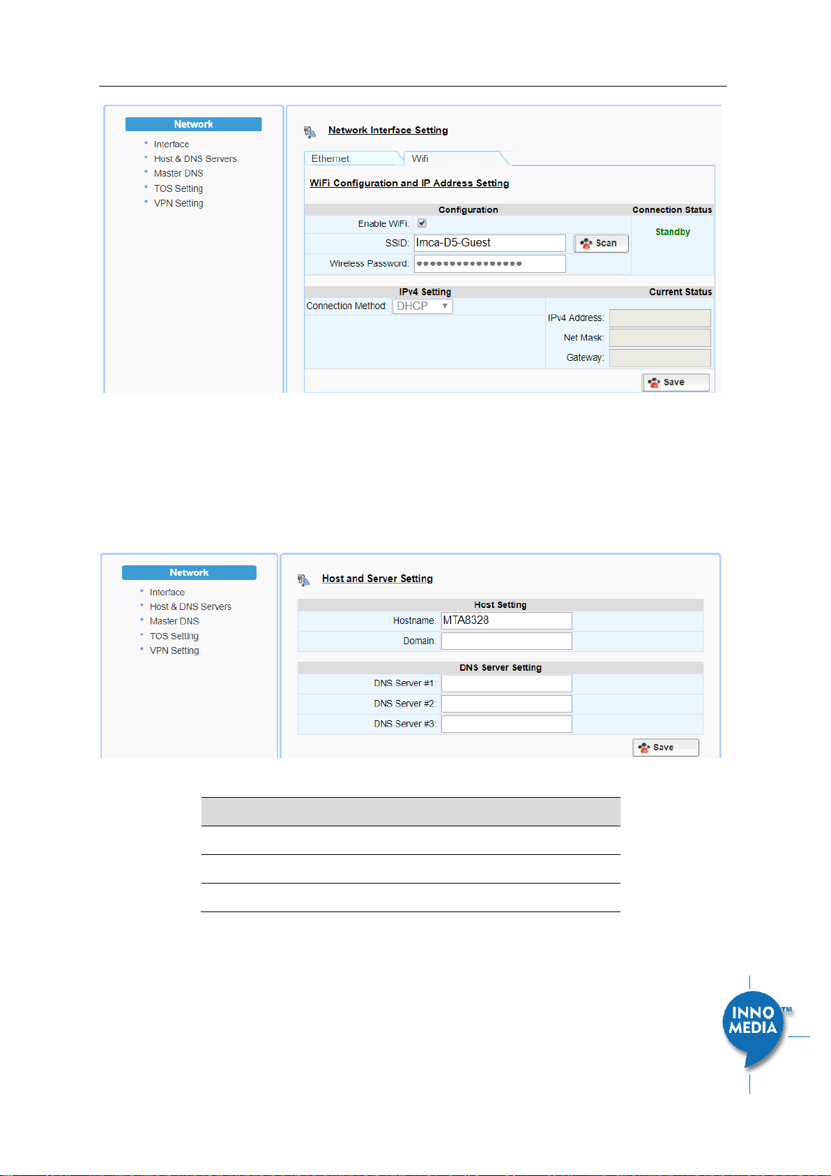
3.1.2 WiFi Configuration and IP Address Setting
This page is applicable to the HG8328-1W model.
InnoMedia HG8328-1W Administrative Guide
Page 14
Copyright © 2019 InnoMedia. All rights reserved.
Figure 6. WiFi Configuration and IP Address Setting
Select a WiFi SSID and input the password (Pass Phrase) for WiFi Access Point. Note that the WiFi password
cannot be retrieved from this page by the administrator if it is entered through the Captive Portal page.
3.2 Host and DNS Servers
Configure the host and the DNS server information provided by your network operator.
Figure 7. Configuring the host information on the device
Field Name
Description
Host Name
Configure the host name for the device.
Domain
Configure the domain name for the device.
DNS Server Setting
Allows configuration of up to three DNS servers.
3.3 Master DNS
“Master DNS” is the IP address of the domain name server specified by the telephony service provider rather
than the internet service provider. If “Master DNS” is configured, the MTA gets related DNS services from this

InnoMedia HG8328-1W Administrative Guide
Page 15
Copyright © 2019 InnoMedia. All rights reserved.
configured server to perform voice communication functions. The MTA acquires DNS information from the
following servers in the priority shown (in order of decreasing priority):
1. Master DNS
2. DHCP Option (Ethernet IP Address Setting)
3. Manually configured DNS (see section 3.2)
Figure 8. Configuring the Master DNS Information
Field Name
Description
DNS Server
Configure the DNS server information
specified by the VoIP service provider for up
to 3 DNS servers.
3.4 TOS Setting
TOS (Type of Service) is a part of the IPv4 header which is used for precedence, or in other words categorizing
traffic classes. The higher the value of the IP Precedence field, the higher the priority of the IP packet.
Figure 9. TOS Setting
Field Name
Description
TOS Setting
Host Traffic: Use the configured TOS value to
tag data traffic other than SIP or RTP
packets.
VoIP Signal Traffic: Use the configured TOS
value to tag SIP signaling packets.
Voice Traffic: Use the configured TOS value
to tag voice RTP packets.

InnoMedia HG8328-1W Administrative Guide
Page 16
Copyright © 2019 InnoMedia. All rights reserved.
3.5 VPN
To setup the HG3828 to run as a VPN client, import the files which are provided by service providers, enable
VPN and save the configurations.
Once enabled, the HG8328-1W will automatically setup a VPN tunnel for voice services.
Figure 10. VPN client setup

InnoMedia HG8328-1W Administrative Guide
Page 17
Copyright © 2019 InnoMedia. All rights reserved.
4TELEPHONY
The Telephony section is used to configure SIP Parameters, telephony settings (including regional settings)
and line diagnostics.
Figure 11 Configuring Telephony options
4.1.1 Profile Config
Profiles include SIP Server/Proxy Settings, Security Settings, Codec Settings, SIP Timer Settings, Digitmap
Settings, FXS Settings, Feature and Service Code Settings, Fax Settings and Call Report Settings which are
described in the following sections.
Click on the Edit icon of a particular profile to display the profile setting screen.
4.1.2 SIP Server Setting
Figure 12. SIP Server Setting—SIP Proxy Server
Field Name
Description
Profile Name
Up to 4 profiles can be created. (The profile
ID corresponds to the No. in the Profile List.)
Proxy Server
The FQDN or IP address of the SIP proxy
server
Local SIP Port
The SIP port used on the MTA
Preferred
Transport Protocol
If there are no queried NAPTR records
specifying the transport protocols to be
used, the MTA uses this configured setting

InnoMedia HG8328-1W Administrative Guide
Page 18
Copyright © 2019 InnoMedia. All rights reserved.
to set up VoIP calls with the SIP server.
UDP | TCP | TLS
Enable Outbound
Proxy
If enabled, the MTA uses the value
configured in “Proxy Server” as the
outbound proxy server setting.
SIP Domain
The MTA uses this setting to (1) compose
the host part of SIP request URI strings and
(2) perform NAPTR/SRV queries.
Access Network
Info
This header is useful in SIP-based networks
that also provide layer 2/layer 3 connectivity
through different access technologies. SIP
User Agents may use this header to relay
information about the access technology to
proxies that are providing services.
Allowed for Reg.
Retry
Upon registration failure, the configured
registration response SIP error codes can be
used to trigger re-registration. If multiple
error codes are to be used, use a comma (,)
to separate them. No entry indicates
registration is always retried if registration
fails.
SIP Proxy-Require
Header
The Proxy-Require header field is used to list
features and extensions that a UA requires a
proxy to support in order to process the
request.
Figure 13. SIP Server Settings –SIP Option

InnoMedia HG8328-1W Administrative Guide
Page 19
Copyright © 2019 InnoMedia. All rights reserved.
Field Name
Description
100rel Support
Enable 100rel response support.
Enable Switching
Proxy in Response
to DNS SRV Priority
Change
When this item is enabled, whenever the
MTA is ready to send a REGISTER request
and the SRV TTL has expired, it performs an
SRV query and the MTA will switch to the
most preferred SIP server (lowest priority) in
the SRV query response.
If this item is disabled, the MTA stays with
the currently registered SIP proxy and only
saves the SRV query results. However, if the
current SIP proxy is unreachable, or the MTA
reboots and starts a new DNS query process,
the MTA will then register to the most
preferred SIP server (lowest priority) in the
SRV query response.
Disable rport
Support
Do not append rport (response port
number) in the Via header.
Using SIP Notify for
Flashhook Support
Send a SIP NOTIFY hook flash event message
during the call when a hook flash is
detected.
Using SIP Info for
Flashhook Support
Send a SIP INFO hook-flash event message
during the call when a hook flash is
detected.
SIP Short Header
Support
Send SIP Headers in short format (compact
form) to reduce message packet size.
Enable Re-
registration
Credential
Enable Re-registrations to carry the previous
successful authentication credentials.
OutOfBand DTMF
by SIP
Use SIP INFO to send DTMF.
RFC2833 DTMF
Use RFC2833 for sending DTMF digits.
Available options:
Negotiated –MTA and SIP Server
negotiate if RFC2833 is enabled or not.
Always off –RFC2833 is never used.
Always on –RFC2833 is always used.
Send UA Header
Allow MTA to send User-Agent Header in SIP
message.
UA Header Format
User-Agent Header sent out is modifiable.

InnoMedia HG8328-1W Administrative Guide
Page 20
Copyright © 2019 InnoMedia. All rights reserved.
(Note: If “SIP Short Header Support” is
enabled, there will be no UA Header in SIP
messages.)
Available parameters:
Model name ($MOD)
MAC ($MAC)
Version ($VER)
Example Syntax: $MOD $MAC $VER.
Output: SIP User-Agent: MTA-8328-1N
001099112233 V1.0.0.0
Refer at End of
3way Call
Send REFER when mixer (local MTA) hangs
up, so the other two parties can continue
the conversation.
Accept
resync/check-
sync/reboot
When enabled, the MTA device supports
events triggered by SIP NOTIFY messages
sent to the MTA from the SIP server. Event
types are:
(1) check-sync. MTA reboots itself and
starts provisioning process.
(2) reboot. MTA reboots itself (and starts
provisioning process).
(3) resync. MTA starts provisioning process
only.
Call Hold with Zero
IP
Use 0.0.0.0 in SDP for call hold.
Hook Flash MIME
Type
Input the MIME type string for Flash hook
events.
4.1.3 Security Setting
Figure 14. MTA Security Settings
Field Name
Description
Enable SIP Server
List
When this feature is enabled, the MTA
checks all incoming SIP request messages for
their source IP addresses. If the source IP is
not in the “SIP Server list”, the MTA rejects
or drops this message.
Table of contents
Other InnoMedia Telephone manuals


