InnoMedia MTA8328-4 User manual

1
InnoMedia
Business VoIP ATA Models
MTA8328-4, MTA8328-8, MTA8328-24
Quick Installation Guide
Introduction
Expanding on InnoMedia’s widely deployed Broadband IP Telephony product family, the
MTA8328 provides crystal-clear wideband voice communications with a high degree of
manageability, allowing rapid and scalable SOHO/Enterprise VoIP service deployment.
Package Contents
1 MTA
1 RJ-45 Ethernet Cable
1 Quick Install Guide
Power Input:
1 12V AC Power Adaptor (MTA8328-4, MTA8328-8)
1 Power Cable (MTA8328-24)
Important Safety Instructions—Protective Earthing
Protective
earthing is used as a safeguard. This equipment must be earthed. The
power plug must be connected to a properly wired earth ground socket outlet. An
improperly wired socket outlet could place hazardous voltage on accessible metal
parts.
Installation: MTA8328-4 MTA8328-8
MTA8328-4 Backview
MTA8328-8 Backview
Plug the supplied power adapter into the MTA8328 “12V DC” socket. The
power LED will show steady green.
Connect phones or other analog devices into any of the PHONE ports on the
MTA.
Setup the MTA to connect to the Internet. Connect the yellow Ethernet cable
(supplied) into the WAN port on the MTA and connect the other end into an
available Ethernet port on your router or network switch.
Confirm that the MTA is successfully connected to the Router and acquires an IP
address. See WAN LED states in the LED table below to confirm that the MTA is
connected. The MTA WAN interface is configured as a DHCP client by default,
and may obtain an IP address from a DHCP server.
Once the MTA connects to the voice service provider network, and completes
the registration and service provision process, a solid green PHONE LED should
be displayed.
2
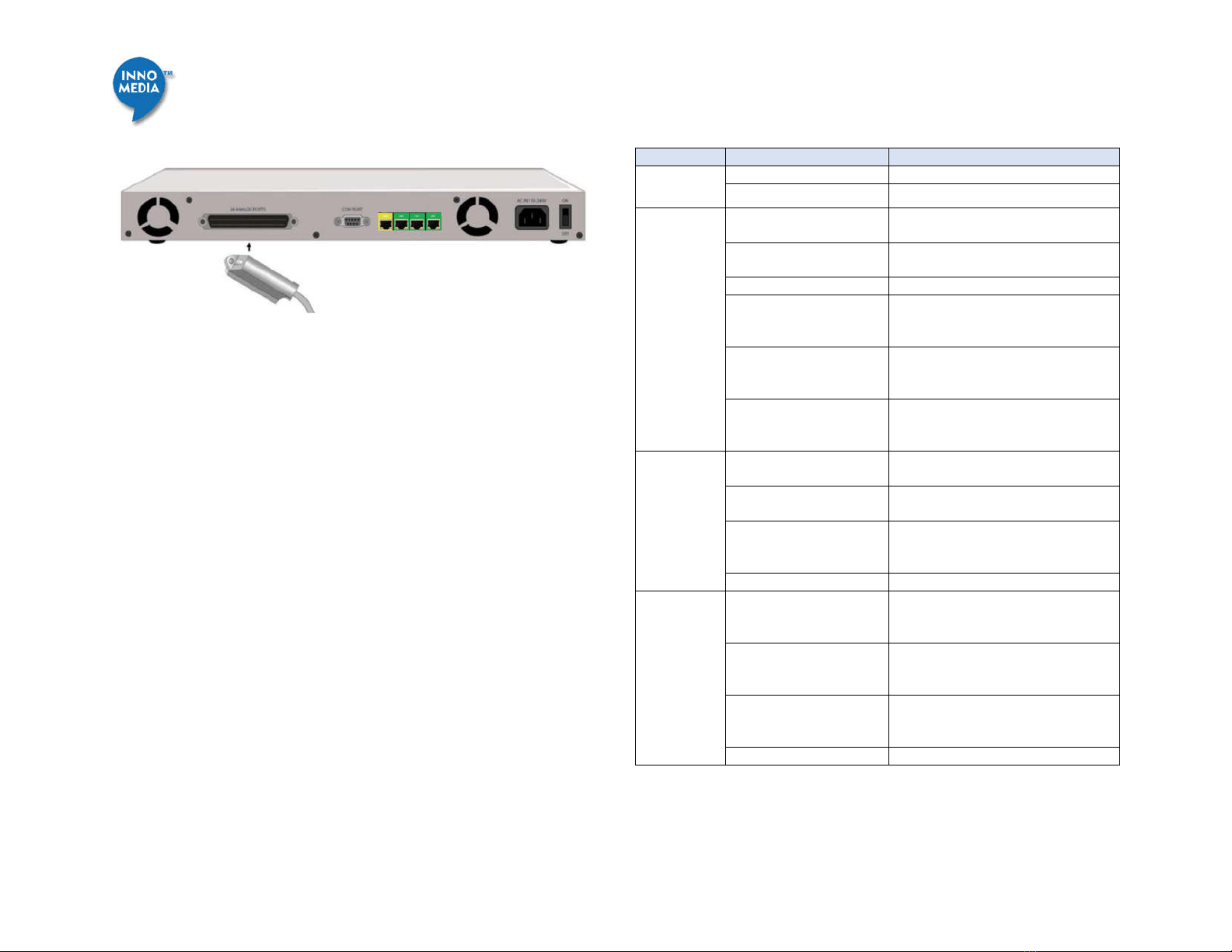
Installation: MTA8328-24
Plug the supplied AC power cable into the MTA’s “AC IN 110-240V” connector.
Connect a 25 pair/50 pin Amphenol cable to the MTA’s “24 ANALOG PORTS”
connector. The Amphenol cable should be connected to a patch panel with RJ-
11 ports. Connect phones or other analog devices to the RJ-11 ports on the
patch panel.
Setup the MTA to connect to the Internet. Connect the yellow Ethernet cable
(supplied) into the WAN port on the MTA and
connect the other end into
an available Ethernet port on your router or network switch.
Confirm that the MTA is successfully connected to the Router and acquires an IP
address. See WAN LED states in the LED table below to confirm that the MTA is
connected. The MTA WAN interface is configured as a DHCP client by default,
and may obtain an IP address from a DHCP server.
Once the MTA connects to the voice service provider network, and completes
the registration and service provision process, a solid green PHONE LED light
should be displayed.
LED Status Summary
LEDs Blinking State MTA8328 State
PWR
Steady Green Powered ON.
Off Powered OFF.
WAN
Solid or Blinking Green WAN Ethernet 1000BT link is active,
blinks with activity.
Solid or Blinking Yellow WAN Ethernet 10/100BT link is
active, blinks with activity.
Off WAN Ethernet link is not connected.
Fast Blinking Green
(0.25 secs on, 0.25 secs
off)
WAN Ethernet 1000BT link is active
but is unable to reach the Internet.
Fast Blinking Yellow
(0.25 secs on, 0.25 secs
off)
WAN Ethernet 10/100BT link is active
but is unable to reach the Internet.
Medium-Slow Blinking
Yellow (1 sec on, 1 sec
off)
Device firmware is being upgraded.
The PHONE LED blinks in unison with
all other LEDs (except PWR LED)
LAN
Solid Green LAN Ethernet 1000BT link is active,
blinks with activity
Solid Yellow LAN Ethernet 10/100BT link is active,
blinks with activity
Medium-Slow Blinking
Yellow (1 sec on, 1 sec
off)
Device firmware is being upgraded.
The PHONE LED blinks in unison with
all other LEDs (except PWR LED)
Off LAN Ethernet link is not connected.
RUN Fast Blinking Green
(0.25 secs on, 0.25 secs
off)
Device is being provisioned or
firmware is being upgraded.
Fast Blinking Red
(0.25 secs on, 0.25 secs
off)
Device provisioning or firmware
upgrade has failed.
Solid Green Device has been provisioned or
firmware upgraded has been
successful.
Off Device has provisioning disabled.

3
PHONE 1
through 24
(depending
on Model)
Off - No power, OR
- Device is initializing, OR
- Failed to register for voice services,
OR
- Line is disabled.
Steady Green The device is ready to make calls.
Slow Blinking Green (3
secs on, 1 sec off)
There are new voicemail messages.
Medium-Fast Blinking
Green (0.5 secs on, 0.5
secs off)
The device is registered and ready to
make calls, and the line is in use.
Fast Blinking Red (0.25
secs on, 0.25 secs off)
One or more line diagnostics tests
(GR-909) failed. This state is cleared
when the GR-909 tests are run again
and all tests pass, or when the device
is rebooted.
Wall-Mounting Instructions –MTA8328-4, MTA8328-8
Optionally, you may choose to mount your MTA on the wall.
1. Use the provided template to drill two holes on the wall.
2. Use a screwdriver to install one #6 metal screw in each hole. Leave the screw
heads 1/4 to 3/8 inch away from the wall.
3. Position the MTA with the ports at the top.
4. Place the unit above the screws and lower it so the screw heads are inside and
at the tops of the wall mount slots on the back of the unit.
5. Adjust to ft. If the unit is too loose, remove it from the wall, slightly tighten
screws, and rehang.
MTA8328-4
MTA8328-8
Wall-Mounting Instructions – MTA8328-24
A wooden back-board is recommended for wall mount. Install 4 wood screws or
wall-mount mounting screws (not provided) into the back-board or the wall.
Rack-Mounting Instructions – MTA8328-24
Install 4 rack-mount screws (not provided) into the mounting holes of the rack and
tighten firmly.
Rack Mounting Wall Mounting
1
Machine Screw Diameters
Size
Thread Diameter
Decimal Nearest
Fractional
Threads per inch
Screw Length
#6 0.138" 9/64" 18 1-1/2”
#6 metal
screws
#6 metal
screws
6.6” 5.12”

4
Important Safety Instructions
This section contains important safety information you should know before
working with the DEVICE. Use the following guidelines to ensure your own personal
safety and to help protect your DEVICE from potential damage.
This warning symbol means danger. You are in a situation that could
cause bodily injury. Before you work on any equipment, be aware of the hazards
involved with electrical circuitry and be familiar with standard practices for
preventing accidents
Only trained and qualified personnel should be allowed to install, replace, or
service this equipment.
To avoid electric shock, do not connect safety extra-low voltage (SELV) circuits to
telephone-network voltage (TNV) circuits. LAN ports contain SELV circuits, and
WAN ports contain TNV circuits. Some LAN and WAN ports both use RJ-45
connectors. Use caution when connecting cables. Statement 1021
Before working on a system that has an on/off switch, turn OFF the power
and unplug the power cord.
This unit is intended for installation in restricted access areas. A restricted
access area is where access can only be gained by service personnel through the
use of a special tool, lock and key, or other means of security, and is controlled by
the authority responsible for the location.
This product relies on the building’s installation for short-circuit
(overcurrent) protection. Ensure that a fuse or circuit breaker no larger than 120
VAC, 15A U.S. (240 VAC, 10A international) is used on the phase conductors (all
current-carrying conductors).
This equipment must be grounded. Never operate the equipment in the
absence of a suitably installed ground conductor. Contact the appropriate electrical
inspection authority or an electrician if you are uncertain that suitable grounding is
available.
Do not work on the system or connect or disconnect cables during periods
of lightning activity.
Before working on equipment that is connected to power lines, remove
jewelry (including rings, necklaces, and watches). Metal objects will heat up when
connected to power and ground and can cause serious burns or weld the metal
object to the terminals.
The safety cover is an integral part of the product. Do not operate the unit
without the safety cover installed. Operating the unit without the cover in place
will invalidate the safety approvals and pose a risk of fire and electrical hazards.
Enclosure covers serve three important functions: they prevent exposure to
hazardous voltages and currents inside the chassis; they contain electromagnetic
interference (EMI) that might disrupt other equipment; and they direct the flow of
cooling air through the chassis. Do not operate the system unless all covers are in
place.
Ultimate disposal of this product should be handled according to all national
laws and regulations.
To prevent bodily injury when mounting or servicing this unit in a rack, you
must take special precautions to ensure that the system remains stable. The
following guidelines are provided to ensure your safety:
This unit should be mounted at the bottom of the rack if it is the only unit in
the rack.
When mounting this unit in a partially filled rack, load the rack from the
bottom to the top with the heaviest component at the bottom of the rack.
If the rack is provided with stabilizing devices, install the stabilizers before
mounting or servicing the unit in the rack.

5
Federal Communication Commission Interference Statement
This device complies with Part 15 of the FCC Rules. Operation is subject to the
following two conditions: (1) This device may not cause harmful interference, and
(2) this device must accept any interference received, including interference that
may cause undesired operation.
FCC Radiation Exposure Statement:
This equipment complies with FCC radiation exposure limits set forth for an
uncontrolled environment. This equipment should be installed and operated with
minimum distance 20cm between the radiator & your body.
Copyright Notice:
© 2018, InnoMedia Inc., All rights reserved. This documentation is the proprietary
intellectual property of InnoMedia Inc.
Other manuals for MTA8328-4
1
This manual suits for next models
2
Table of contents
Other InnoMedia Telephone manuals


