Innoquest SpotOn G2 User manual

Product Manual
Innoquest Item # 23920

1
Table of Contents
1.0 Safety Information………………………...2
2.0 Introduction……………………………......3
2.1 Meter Diagram (Front)………………. 3
2.2 Meter Diagram (Back)………………. 3
2.3 Features……………………………….4
3.0 Specifications…………………………….. 5
4.0 General Meter Operation………………...6
4.1 Battery Installation……………………6
4.2 Meter Modes…………………………. 7
4.3 How to Make a Probing……………...11
5.0 Software Operation……………………….15
5.1 Software Install………………………. 15
5.2 Software Use………………………….16
6.0 Trouble Shooting………………………….21
7.0 Maintenance………………………………. 22
8.0 Warranty & Service……………………….23
2
1.0 Safety Information
Caution should be exercised while using this meter to assure the
safety of the user. This meter is a low voltage battery powered device
which should not cause electrical hazard to the user even when
connected to a computer via a USB cable. However, please use
caution not to service this meter or connect it to a computer in a wet
environment.
It is recommended that this meter be used with an alkaline 9 volt
battery. Such batteries can leak or explode if an attempt is made to
charge them. Do not recharge disposable alkaline batteries.
It is typical for this meter to be used to measure fats and oils which
can be very slippery when on a users hands or if dropped on the
floor. Please use caution when working around these materials due
to a possible slipping hazard.
3
2.0 Introduction
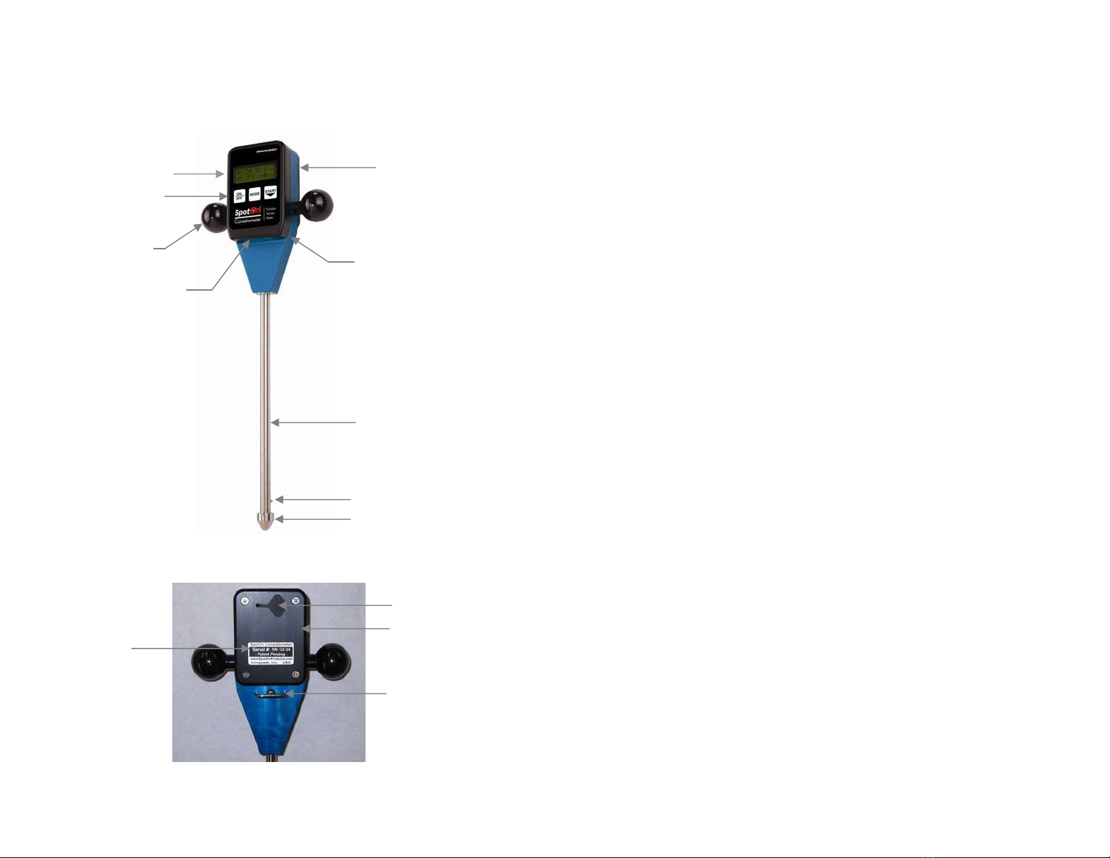
2.1 Meter Diagram (Front)
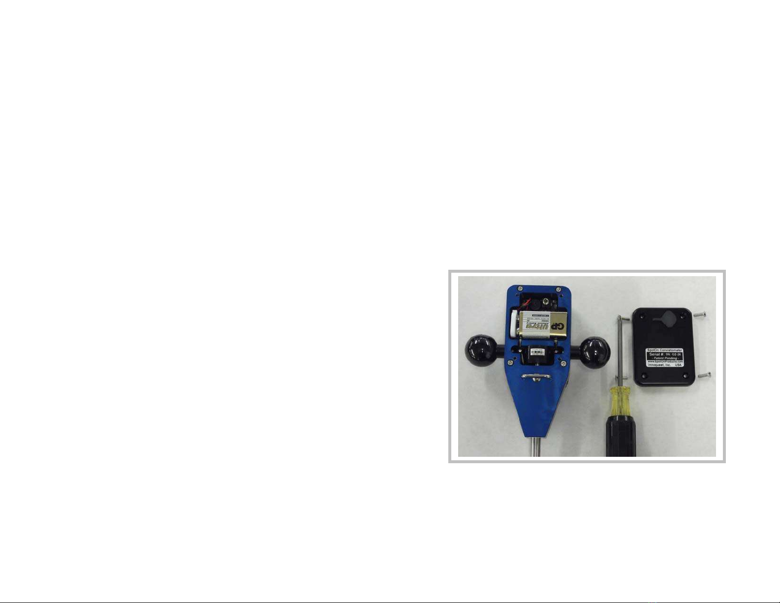
2.2 Meter Diagram (Back)
Remove
Back Plate
To Replace
Battery
LCD Dis
p
la
y
Ke
y
Pad
Tem
p
erature Sensor
Probe Shaft
Probe Tip
(Remove tip to install
shaft extensions
)
Non-Contact
Infrared Depth
Sensor
Internal Load Cell
Measures Penetration
Force From Shaft
Hand Gri
p
s
Wrist Lanyard
Attachment
Loop
Battery Cover
(Remove Back Plate
to Re
p
lace Batter
y)
Data Port Cover
Serial Number
Label
4
2.3 Features:
●Patent Pending Design
●Quick quantitative measurements of product or ingredient
consistency
●Penetrating consistometer measures entire sample, not just the
surface
●Works on a variety of products and ingredients (shortening, frosting,
dough, butter, cheese…)
●Measurements from 5cm up to 70cm depth (over 28 cm depth
require optional shaft extension)
●Shows readings in either Grams or Pounds
●Integrated Temperature Sensor
●On-board microprocessor calculates and displays:
- the average force of a measurement
- the mean of a group of measurements
- the Standard Deviation of a group of measurements
- the equilibrated temperature of the measured sample
●Precision load cell and non-contact depth sensor simultaneously
measure penetration force and penetration depth, while sample
temperature is also measured
●Displays instantaneous penetration speed to guide operator for
repeatable results
●Included PC software allows configuration for many products by
setting the desired penetration rate, depth of measurement, type of
probe tip and min/max limits; all of which can be preloaded onto the
instrument
●Data can be downloaded as an Excel® file (.CSV) for analysis and
plotting
●Interchangeable probe tips can be used to adapt the instrument to
different products (please contact Innoquest for information on
additional probe tips)
5
3.0 Specifications
Force: 0-22 lbs (0-9,999grams) working range, 0.01 lbs (4 g)
resolution, +/- 2% accuracy, Overload protection to 62 lbs (28
kg)
Depth: 0-28 in (0-70 cm) working range, 0.1 inch (0.1cm) resolution,
+/- 0.25” (0.6 cm) accuracy (Accuracy is much higher at
closer ranges and falls off with distance)
Temperature: 32.0-99.9*F (0.0-37.7*C) range, 0.1*F (0.1*C)
resolution, +/-0.5*F (0.3*C) accuracy, time constant approx
20 sec
Data Measurement: Records and displays force reading for every 1
cm (0.4in) of depth up to 70cm (27.6in). (Depending on shaft
length used)
Memory Capacity: Up to 99 probings
Multi Reading Average: Up to 6 probings can be averaged on the
meters display (also calculates standard deviation)
Computer Interface: USB port with special data interface cable
(included)
Battery: Standard 9 volt alkaline battery, 25 hrs continuous use
expected battery life (the meter will automatically shutoff after
2.5 minutes of non-use to save battery life)
Environmental: 35-120*F (2-49*C) / 0-95% RH / Indoor operational
conditions (meter is dust tight but not waterproof)
6
4.0 General Operation
Note: See Demo Video on www.YouTube.com
(Search SpotOn Consistometer)
4.1 Battery Installation
The meter requires a standard 9 volt alkaline battery. Use of
rechargeable batteries is not recommended since the meter won’t
read their remaining life correctly due to voltage differences. The
battery compartment is under the meter’s back cover. Remove the
back cover by first removing the (4) four Philips screws located in its
corners. Changing the battery does NOT erase any of the meter’s
memory; data or settings.

7
4.2 Meter Modes
Once power is turned on to the meter the user has the option to scroll
through and select 4-5 operating modes. (Review Mode does not
show if Data Logging is turned off) Use the MODE button to cycle
through the meter’s modes. The meter will automatically shut off after
2.5 minutes if no buttons are pressed.
Probe Mode – Use this mode to make readings. The meter
defaults to this mode when turned on.
Calibrate Mode – Use this mode to calibrate the meter.
Calibration is required when changing tips or shaft
configurations and recommended at the start of each day for
best accuracy.
Setup Mode – Use this mode to change meter settings for
units of measure or to turn data logging on or off.
Raw Mode – Use this mode to see raw sensor data. This
mode is primarily used for trouble shooting and not needed
for normal operation.
Review Mode – Use this mode to review a previous probing.
This mode only shows and works when data logging is turned
ON.
4.2.1 PROBE MODE
Probe mode is for taking readings with the meter and is
detailed below in section 4.3. The meter can operate
with or without saving readings to a data file. This
logging function is set as described in Setup Mode
section 4.2.3. If the logging is turned OFF then the meter
can still take readings and calculate multi-probe averages
but none of the data is stored for later download or for
review in Review Mode. When logging is turned ON the
meter tracks probings in its data file with an “N” number.
This number is consecutively assigned to each probing
while the logging function is on and is reported on the
meters LCD and later in the data file so the user can
track where the probing came from with his/her notes.
When the logging function is off, the “N” number will only
show as “- -“. It is possible to turn the logging function on
and off as many times as desired during a days work but
only readings taken while logging is on will be in the data
file. Turning off the logging function does not delete
previously recorded data.
8
Step 2
4.2.2 CALIBRATE MODE
This mode is used to calibrate the meter’s internal load
cell for drift which can occur due to temperature changes
or impact to the meter’s shaft. It is required that
calibration be done when ever a probe tip is changed or
shaft extensions are added or removed since the weight
of the shaft assembly is determined during calibration. It
is recommended that calibration be done at the start of
each day for best meter accuracy.
Select the CALIBRATE Mode and then press the START
button to begin calibration.
The meter goes through a 2 step
process to calibrate the load cell and
measure the weight of the shaft and tip
currently installed. First the meter asks
for the user to “Hang Shaft” this means
to hold the meter up by the handles and
allow the shaft to hang freely down
without touching anything (see Step 1
photo). Press the START button and
wait for the meter to finish. The meter
then asks for “Shaft Up Now” this
means that the meter must be place up-
side-down on a flat stable surface so
that the shaft is pointing straight up in
the air (see Step 2 photo). This will
allow the meter to measure only the
weight of the shaft and tip as
configured. With the meter sitting on it’s
“head” press and release the start
button and wait for the meter to finish
calibration. Note that the meter will
automatically ask for a calibration if it
detects a change in the shaft length
being used.
Step 1

9
4.2.3 SETUP MODE
Once in Setup Mode press the START button to select
which parameter to change.
a. UNITS screen allows the user to change the
measurement units of the meter between Metric
and Imperial. Press the MODE button to enter
the units screen and then change the units with
the START button. Note there are two units
screens; one for force/depth and one for
temperature. When done press the MODE
button to exit Setup Mode. The measurement
units can also be changed with the PC software.
Either method has the same effect.
b. DATA LOGGING screen allows the user to select
if the meter is configured to save probing data to
its memory for later download to a computer or
review. Press the MODE button to enter the data
logging screen and then change the setting with
the START button. When done press the MODE
button to exit setup mode. Unless no PC is
available or desired for operation it is best to set
data logging ON.
10
4.2.4 RAW MODE
This mode allows the user to see the raw readings from
the different sensors on the meter. While in this mode
the user can press the START button to scroll through
several other screens used for diagnostic or
troubleshooting work. All of these screens are read only
so no parameters can be accidentally changed. Exit raw
mode at anytime by pressing the MODE button.
4.2.5 REVIEW MODE
This mode allows the user to see data from previous
probings (only available if data logging is turned on).
Pressing the START button again will allow the user to
scroll down through the previous probings. Once the
probing of interest is reached then press the MODE
button to select it. At this point the START button will
allow the user to see the data from this probing including
each 1 cm of recorded data by continuing to press the
START button. When done press the MODE button to
return to the review mode.
11
4.3 How to Make a Probing
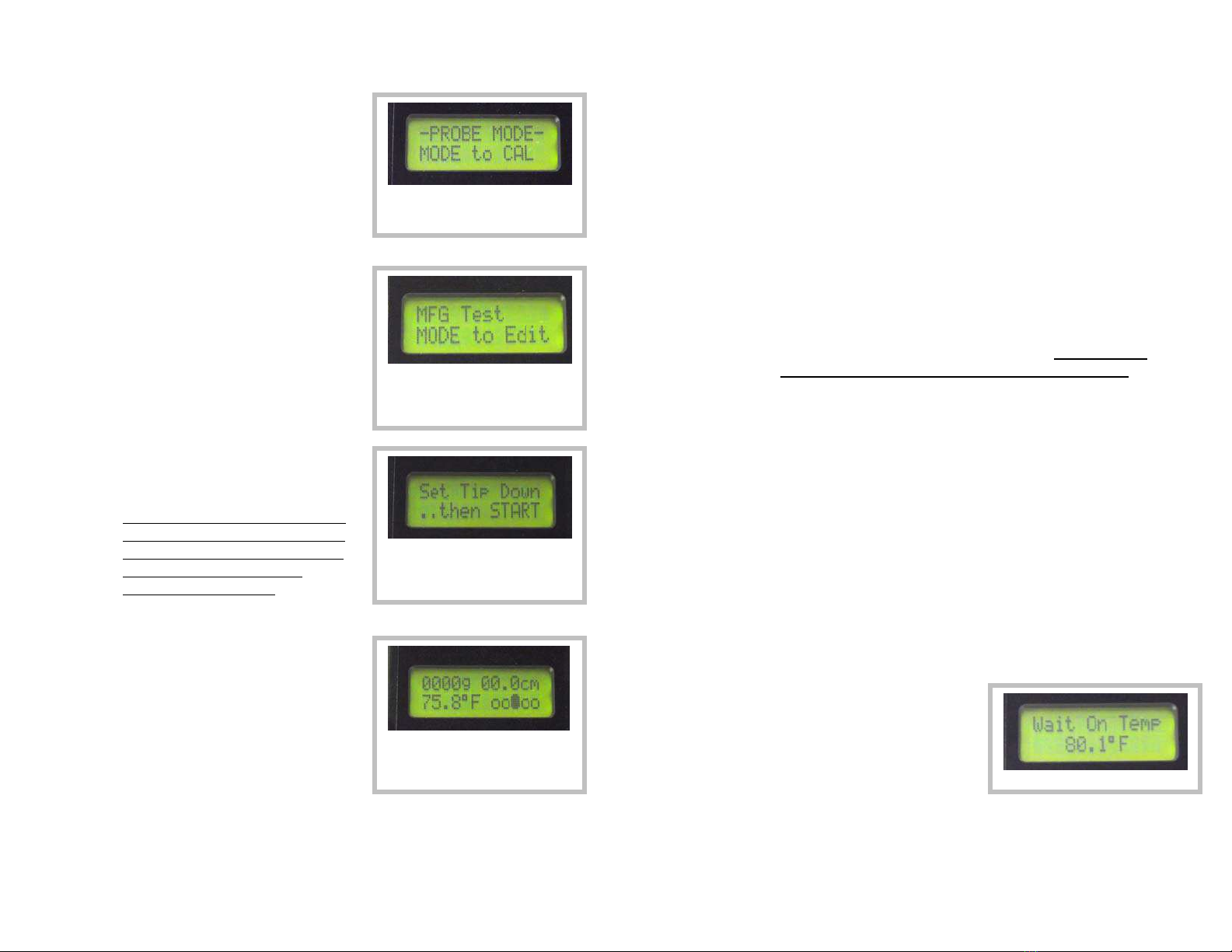
4.3.1 Turn the meter on and select
PROBE MODE if not already on
the screen as shown. (At power
on wait for the splash screens for
battery % and memory full to
finish displaying.)
4.3.2 Press START to begin a reading
once in PROBE MODE, if the
meter was just turned on then the
Product Type last used will be
displayed. If the product type
needs to be changed then press
MODE.
4.3.3 Once the START button is
pressed again the meter will
configure itself for a probing.
Turning the meter OFF and then
back ON will allow selection of a
new Product Type and will reset
all averages and standard
deviation calculations.
4.3.4 Place the meter’s tip on the
surface of the sample and press
START again. The meter will
measure the distance to the
surface for use in calculating
depth during the probing and for
checking probe length for
reporting in the data file. If the
probe length measured does not
match the currently calibrated configuration the meter may
suggest a new calibration is required. Once this screen
appears the user can then proceed by pushing the probe into
the sample.
Defaults to PROBE MODE after
power on, press START to
continue
Select Product Type, START to
continue, MODE to change
Product Type (“MFG Test” is the
Product Type shown here)
When this screen shows set the
meter’s tip on the surface of the
product but DO NOT start
p
enetratin
g
y
et.
When this screen appears the
probe may be inserted into the
product.
12
i. While pushing the probe into the sample watch the
speed indicator in the lower right of the screen. For the
selected insertion speed the indicator must be centered
(ooOoo). If the speed is too fast then the indicator
moves to the right (oooOo). If the speed is too slow
then the indicator moves to the left (oOooo). For
reference: (Ooooo)= 60% of target speed,
(oOooo)=80%, (ooOoo)=100%, (oooOo)=120%,
(ooooO)=140%.
ii. During the probing the force measured and the depth
will be continuously updated on the screen. The meter
will record a force reading at each 1 cm of depth and
save them to calculate a probing average and also for
later review or download to a computer if the logging
function is enabled. Probe averages discard the first 3
cm and the last 1 cm of probing depth. Therefore the
minimum probing depth is 5 cm for a valid reading.
4.3.5 For the meter to allow a probing to be considered complete
the penetration depth must be at least 5 cm. Once the
probing has gone to 5 cm or deeper then the probing reading
can be completed in two ways.
i. The downward penetration can be stopped and the
probe pulled out of the sample, once it has been
withdrawn 4 cm the meter will complete the probing
and then take the temperature that is currently sensed
by the temp sensor and then show FINISHED on the
LCD as shown on the next page.
ii. OR the downward penetration can be stopped at any
depth beyond 5 cm and the meter is left to sit without
further penetration or significant withdrawal for 4
seconds. After this 4 second wait the meter will
recognize that the user
intends to stop the probing
and will automatically enter
a temperature stabilization
mode (looks for less than
0.1*F change every 3
seconds). Once in this
mode it will monitor the temp sensor and only complete
the reading once the temperature measurement has
stabilized. Once stabilized the meter will complete the
probing and show FINISHED on the LCD.
Temp Stabilization Mode
13
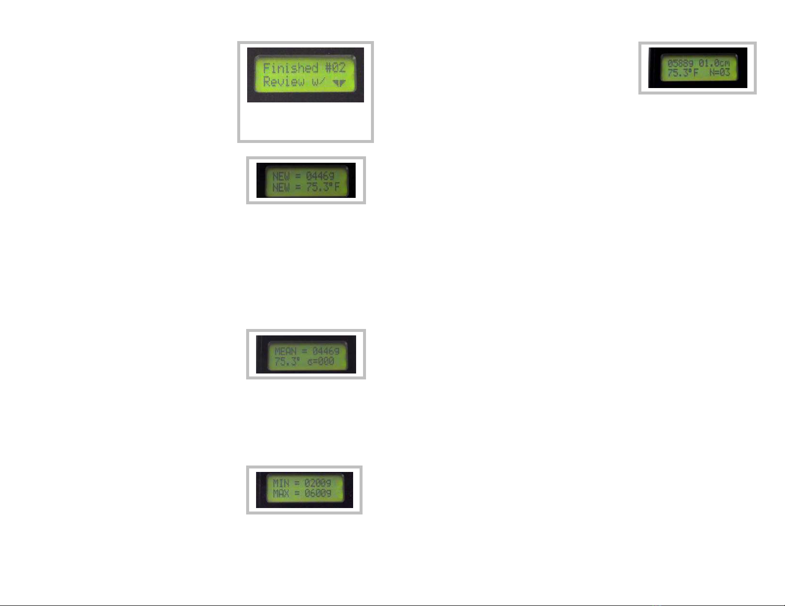
4.3.6 Once the meter has just finished
a probing (before starting a new
probing) the user can see 3-4
types of data. Pressing the
START button will show the data
in the following order. If data
logging is enabled then this data
can also be viewed later through
the use of Review Mode.
SCREEN 1 - The probing force
average and temperature for the
current reading called “NEW”. The
first 3cm and last 1cm of data are
not used in computing this average.
If more than 50% of the recorded force readings for the
probing profile were at speeds greater or less than the middle
three speedometer display segments (greater then +/- 20% of
target speed) then the entire probing is rejected and the user
is instructed to take a new one. This keeps operator error
from producing bad data sets. If a Max Depth was set
through the PC software for this product type then the
average as described above will only be calculated on data
points up to the set Max Depth.
SCREEN 2 - The multi-probe mean
of both force and temperature for all
probings since the meter was
turned ON. The standard deviation
is also displayed for all readings
included in the mean (shown as the Greek symbol sigma).
The meter will only calculate the mean and std dev for up to 6
probings. If more than 6 probings are taken without turning
the meter off/on then the mean will show as 0. To reset this
multi-probe averaging function turn the meter OFF then back
ON.
SCREEN 3 - The min and max
values are displayed as set through
the PC software for the currently
selected product type. If the min
and max are set to 0 and 9999
respectively then this min/max screen will not show.
This screen shows when the
probing is completed. (whether by
stopping the insertion and waiting or
immediately withdrawing the probe)
14
SCREEN 3/4 & Up - Pressing the
START button additional times will
allow the user to cycle through the
readings held in temporary memory
for each 1 cm of probing depth.
These readings are only recorded for computer download if
the logging function is ON. Once the max probing depth has
been displayed the display will cycle back to the SCREEN 1
in a continuous loop. In this way you can always get back to
a reading if you accidentally pressed the start button too
many times.
Pressing the MODE button at anytime will exit the review
mode and ready the meter for another probing. Once this is
done the data described above is no longer available to view
unless data logging was ON.

15
5.0 PC Software
The SpotOn Consistometer PC software is used for the following:
- Before the meter can communicate with the PC a correct com
port must be selected. (see 5.2.1)
- Transfer of data from the meter to a file on the PC (see 5.2.2)
- Clearing the data memory on the meter (see 5.2.3)
- Configuring settings on the meter (see 5.2.4
5.1 Software Install
Software Installation:
Insert the SpotOn Consistometer Software CD in the computer’s CD
drive. This should automatically start a software install wizard on the
PC. Follow the steps on the install wizard to install the software.
Once the software is installed the CD will run a program that installs
the driver for the USB cable. This will be seen as a small “command
prompt” window that will flash on the screen for a few seconds. When
this is finished the install process is complete and the software and
USB cable should be ready to use.
Note: If there is a problem installing the software then locate the
SpotOn Setup.exe on the CD and right click on it, then select
windows compatibility mode and run as XP compatible.
USB Cable Installation:
The meter has a data port for connection to a computer via a special
USB cable that was provided with the meter. This cable requires a
driver be installed on the computer for proper operation. The
software CD that comes with the meter will automatically install this
driver when installing the meter’s software as described above.
PLEASE NOTE: Don’t plug this USB cable into the computer until
after the software has been installed. If it is plugged in before the
install please remove it and CANCEL all requests by the “New
Hardware Wizard”.
16
5.2 Software Use
5.2.1 Port Selection
1. Make sure the meter has a battery installed. The meter should be
turned off. Attach the Special USB cable to a USB port on the
computer and to the data port on the meter.
2. After opening the SpotOn Meter Software enter the Port Select
menu and click on AUTO DETECT. This will cause the software to
search the computer to find the port the data cable is plugged into.
The com port will be automatically located and saved for future use.
(Note: only works when the meter is connected to the computer with
the USB cable) The com port can also be manually selected.

17
5.2.2 Transferring Meter Data
Enter the Meter menu and select GET DATA FROM METER to
download all data on the meter. This will create a .CSV (comma
separated variable) file which can be read by any spread sheet
program. Note: All data stays on the meter even after a download or
after changing the meters battery. The ONLY way to clear the data
from memory is described in section 5.2.3.
Data File Example Opened in a Spread Sheet Program:
18
5.2.3 Clearing Meter Memory
Clear the meters memory when desired by entering the Meter menu
and selecting CLEAR METER MEMORY. This will clear all data from
the meter’s memory. Note that this does not affect settings or stored
Product Type names.

19
5.2.4 Configuring the Meter
A list of Product Types can be generated by entering the Meter menu
and selecting CONFIGURE PRODUCT LIST. The Product Types
entered will automatically be saved and redisplayed when the
software is re-opened. Only the Product Types which have been
selected with a check mark will be sent to the meter. The user can
then scroll through the transferred Product Types while using the
meter in the field to select the one desired before a reading is taken.
Product Types -
Send Check Box – If this box is checked then its associated
product type will be sent to the meter. By checking or un-
checking this box the number of product types to scroll through
on the meter is limited while still allowing all data to be store in
the PC file. All the data is stored in the file: SpotOn Settings.cfg.
This file can be copied to other computers to eliminate the need
to re-enter all the settings for each computer if desired.
Product Name – Enter up to 12 characters or numbers to create
a unique name that will display on the LCD of the meter once
uploaded.
20
Min – The value entered here will show on the meter’s LCD to
remind the user what the minimum acceptable value is. Set min
to 0 and max to 9999 if no min/max is desired to show on the
meter. Valid ranges are 25 to 9998 grams or 0 to 22.00 lbs.
Max – The value entered here will show on the meter’s LCD to
remind the user what the maximum acceptable value is. Set min
to 0 and max to 9999 if no min/max is desired to show on the
meter. Valid ranges are 25 to 9998 grams or 0 to 22.00 lbs.
Configuration – This is a pull down menu that allows the user to
select one of the custom named “configurations” as defined in the
Set Up Configuration section. A configuration MUST be selected
for each product type.
Set Up Configuration -
Configuration Name – This is a custom name the user can enter
up to 15 characters to describe the configuration (i.e.
“shortening”, “dough”, “icing”…). This name will show in the pull
down menu in the product types section above.
Penetration Speed – Select the penetration speed the meter will
use. The default is 3 cm per second.
Tip Type – This is a pull down menu that allows the user to select
from tip numbers 1 to 99. The tip number does not affect the
meter’s operation but is passed on to the data file for ease in
tracking the use of different tips. The default tip is Tip #1.
Max Depth – This sets the maximum depth that will be used to
calculate a probing average on the meter. This setting allows all
data to be calculated to a given depth regardless of the users
actual penetration (provided penetration at least to the Max
Depth).
Select Units -
Units - Select what measurement unit the meter and software will
function in. This setting is not changed on the meter until the
UPDATE METER button is pressed.
Update Meter Button -
Pressing the UPDATE METER button will send all the current
selected product types and units selections to the meter. All of
the settings showing on the screen will be saved to a PC data file
named “SpotOn Settings.cfg” when the software is closed.
Therefore any changes will show the next time the software is
opened.

21
6.0 Trouble Shooting
Why do I get an ERROR after making a probing?
If 50% of the speed readings for a given probing (measured at each 1
cm depth increment) were not within one dot of the center point of the
speedometer then the meter rejects the reading as invalid and show
ERROR on the LCD which requires the user to make the probing
again. With experience the user will get better at producing
consistent penetration speeds that do NOT generate errors. (see
4.3.4)
Why do I get a 0 for mean while the probe average is not 0?
The mean is calculated for up to 6 readings after power on. If the
user takes more than 6 readings the mean and standard deviation will
show as 0’s. Turning the meter OFF then back ON will reset the
counter for up to 6 new readings for which it will calculate mean and
standard deviation. The probe average will always be correct
regardless of the number of readings since power on.
Why don’t I get accurate temperature measurements?
First make sure you are keeping the probe inserted in the product for
4 seconds rather than withdrawing it immediately to end the probing.
If the temperature readings are still not accurate the try withdrawing
the probe 1-2 cm after your full depth is reached. This will help to
insure the temp sensor is in good contact with the product and should
cause it to read better. Note: the probe requires 4 cm of withdrawal
to make it end the probing without waiting for temp stabilization,
therefore it is ok to withdraw 1-2 cm since this won’t break the entry to
temp stabilization mode.
Why does the Speedometer seem “stuck” at the start of the
probing?
The speedometer will automatically show a centered position until the
probe tip reaches a depth of 2 cm. This allows time for the user to
enter the surface of the product and then develop some consistency
to their speed before the speedometer starts showing real values.
Why am I having trouble taking readings near the edge of a
product container?
The meter uses a non-contact infrared sensor which shines an
invisible beam of light out the bottom of the meter front. Make sure its
clear window is clean and that the probe tip is at least 1.5 (3.8 cm)
inches back from the edge of the container so the light beam does not
miss the surface of the product.
22
7.0 Maintenance
- Remove the battery from the meter if it will be stored without
use for a long period of time (like 3 months or more)
- Clean the meter with a soft cloth using soapy water or mild
cleaning agent like Windex®. The meter is sealed against
moisture, dust, and oils but it is not considered water tight and
must NOT be submerged.
- Check the clear window on the bottom edge of the front of the
meter. This is the window over the Infrared depth sensor and
must be kept clean for best performance. Use only soft cloths
for cleaning this window so it does not get scratched.
- Note the purpose of the small o-ring around the threaded end of
the shaft is to provide a self-locking feature to the probe tip so
that it does not come loose during use. The o-ring is
compressed when the probe tip is tightened by hand and
should be sufficient to keep the tip from coming loose. The o-
ring is not designed to form a seal nor is it required for
operation.
- If during normal use an alkaline battery leaks in the meter
please clean the meter immediately and wash hands to remove
any caustic battery electrolyte. The battery electrolyte is water
soluble so please use a wet towel to clean the battery
compartment.

23
8.0 Warranty & Service
One Year Warranty
Innoquest, Inc. warrants this product to be free from defects in
materials and workmanship under normal use and service for a period
one (1) year from date of purchase. This warranty extends only to the
original purchaser and shall not apply to any product which, in
Innoquest’s sole opinion, has been subject to misuse, alteration,
abuse, or abnormal conditions of operation or handling. Innoquest’s
obligation under this warranty is limited to repair or replacement of the
product which is returned to Innoquest. Innoquest accepts no liability
for whatever damages may be caused by a malfunctioning product.
Repair & Service Policy
Product returned to Innoquest for repair or service must follow the
guidelines set forth as follows: Return of the product for warranty or
service repair will be the responsibility of the purchaser (Innoquest
does not pay inbound shipping charges). All returns must receive an
RMA number by calling Innoquest prior to return of the product. The
RMA number must be clearly marked on the outside of the shipping
carton. If the customer is returning product for non-warranty related
repair or service, a minimum charge will apply for accessing the
product’s repair needs and further work will not be completed without
the customer’s approval.
910 Hobe Road
Woodstock, IL 60098
Toll Free: 800-637-1623
Phone: 815-337-8555
Fax: 815-337-8556
www.InnoquestInc.com
© 2012 Innoquest, Inc. USA P/N 27580 Rev. 4 (Revised 10/25/12)
Table of contents
Other Innoquest Measuring Instrument manuals


