InnoSenT iSYS-5005 User manual

Rely on more Senses - www.innosent.de1
iSYS-5005 Evaluaon Kit
User Manual

Rely on more Senses - www.innosent.de | 2
iSYS-5005 User Manual
01. Brief Descripon 5
02. Product Specicaon 6
2.1 Intended Applicaons with the iSYS-5005 7
2.2 Antenna Paern 8
03. Scope of Delivery 9
04. Mechanical Drawing 10
05. Safety Instrucons 11
06. Quick Installaon Guide 12
07. Installaon and Orientaon of the Sensor 14
7.1. Recommended Installaon Height and Mounng Angle 14
08. Connecng 16
8.1. Connector Placement 16
8.2. Power Supply 16
09. Communicaon 17
9.1. Read/Write Conguraon 17
9.2. Object List 18
10. Conguraon using Object Viewer 19
10.1. Installaon of Object Viewer 19
10.2. Launch Object Viewer 19
10.3. Overview of Object Viewer 20
10.4. Connect to Network Camera 20
10.5. Connect to iSYS-5005 Evaluaon Kit 21
10.6. Conguraon Wizard 21
10.6.1. Background 22
10.6.2. Sensor Posion 23
10.6.3. Reference Length 23
10.6.4. Alarm Zones 24
10.6.5. Ignore Zones 25
10.6.6. Sensor Sengs 26
CONTENT

Rely on more Senses - www.innosent.de | 3
iSYS-5005 User Manual
10.7. View Sengs 26
10.8. Object List Object Viewer 27
10.9. Save Conguraon 27
10.10. Record / Playback 28
10.11. Update Firmware 29
10.12. Send Conguraon to System 29
10.13. Read Conguraon from System 29
11. Approvals 30
12. Disposal 31
13. Contact 32
CONTENT

Rely on more Senses - www.innosent.de | 4
iSYS-5005 User Manual
HISTORY
Document
revision
Date Change log Author
12019-03-13 First release MD
1.1 2020-05-08 Update Installaon & Mounng, Communicaon MD
1.2 2020-06-26 Firmware & GUI Update MD

Rely on more Senses - www.innosent.de | 5
iSYS-5005 User Manual
1. BRIEF DESCRIPTION
The iSYS-5005 Evaluaon Kit is a 24GHz MIMO (mulple input mulple output) radar system with integrated signal pro-
cessing designed and developed for security and door opener applicaons.
The newest member of InnoSenT’s radar eet is designed for short-range and wide horizontal view to cover up a big eld of
view. The sensor can be congured in two dierent modes. The mode A (recommended for security applicaons) is set as the
standard mode, the mode B (recommended for door opener or more sensive security applicaons) can easily be changed in
the supplied user interface of the Object Viewer.
Measurement—one sensor, two dierent modes
The sensor uses, with its Doppler based radial moon detecon principle, innovave signal processing for opmal target
detecon. Another special feature is that the sensor can be operated in two dierent modes and is opmally specialized for
the two applicaon areas security or door opener. The desired mode can easily be changed by a sent command or in the
Object Viewer soware. The measurements contain range, radial speed, azimuth angle and received signal strength and
more parameters of the observed objects. This ensures a fast and ecient eld of view coverage for excellent detecon of
moving objects. Due to its high resoluon the iSYS-5005 is capable of separang up to eight objects, set individual alarm &
ignore zones and is protected from an-masking.
Tracking
Aer measuring the parameters of the detecons, the iSYS-5005 uses modern mulple-target tracking algorithms to gener-
ate an object list in every update cycle of 75ms. This object list provides a variety of informaon, such as posion, velocity,
direcon, Object ID and many more.
Applicaons
With its quick and easy conguraon, the iSYS-5005 can be used for a variety of dierent applicaons. The intended use is for
security and door opener applicaons. Challenging scenarios such as moon measurement, suppression of cross trac, me
to arrival and object classicaon and much more can now be solved.
Fig. 1: Front and back side of iSYS-5005 Evaluaon Kit

Rely on more Senses - www.innosent.de | 6
iSYS-5005 User Manual
2. PRODUCT SPECIFICATION
Radar
transmit frequencies ft24.050 24.250 GHz
output power (EIRP) Pout 12.7 dBm
Sensor
detecon range depending on RCS of target dr0.9 ≥ 15 m
standard detecon eld compare with plot on page 8 horizontal ±75 °
vercal ±30 °
velocity range mode A 0.87 55.08 km/h
mode B 0.44 27.54 km/h
range resoluon dres 0.9 m
velocity resoluon mode A vres 0.87 km/h
mode B vres 0.44 km/h
angular resoluon 45 °
update rate 75 msec
Power supply
supply voltage VCC 3.3 5.5 V
supply current ICC 330 mA
Environment
operang temperature TOP -40 +85 °C
storage temperature TSTG -40 +85 °C
Mechanical Outlines
outline dimensions compare to schemac on page 10
height
length
width
50.0
50.0
13.2
mm

Rely on more Senses - www.innosent.de | 7
iSYS-5005 User Manual
2.1 Intended Applicaons with the iSYS-5005
The iSYS-5005 radar sensor has two dierent modes which can be selected in our Object Viewer soware.
The sensor was developed for security and door opener applicaons, but can of course also be used in other applicaons.
Object list: supplies the user with all object parameters, which are sent via UART. This allows the user to implement his own
desired applicaons.
The object list provides the user all the necessary informaon needed to successfully monitor his applicaons. The object list is de-
scribed in the secon [9.2].
Object List
User Own Evaluaon
User Specic
Applicaons
Object List
Object lists have to be requested by the Radar API. The update cycle of the object list is 75ms and a new request must be
sent in order to retrieve the latest object list. The content of each object list, with the parameters of every track, is described
in [9.2.].
The use of object lists allows users to perform their own evaluaons and implementaons of specic applicaons.
iSYS-5005
Door Opener Applicaon
Opening on demand
Cross trac suppression
Zone suppression
Security Applicaon
Intruder Detecon
Standalone System or in
combinaon with camera
Seng Alarm & Ignore
Zones
Other Applicaon
Rely on more Senses - www.innosent.de | 8
iSYS-5005 User Manual
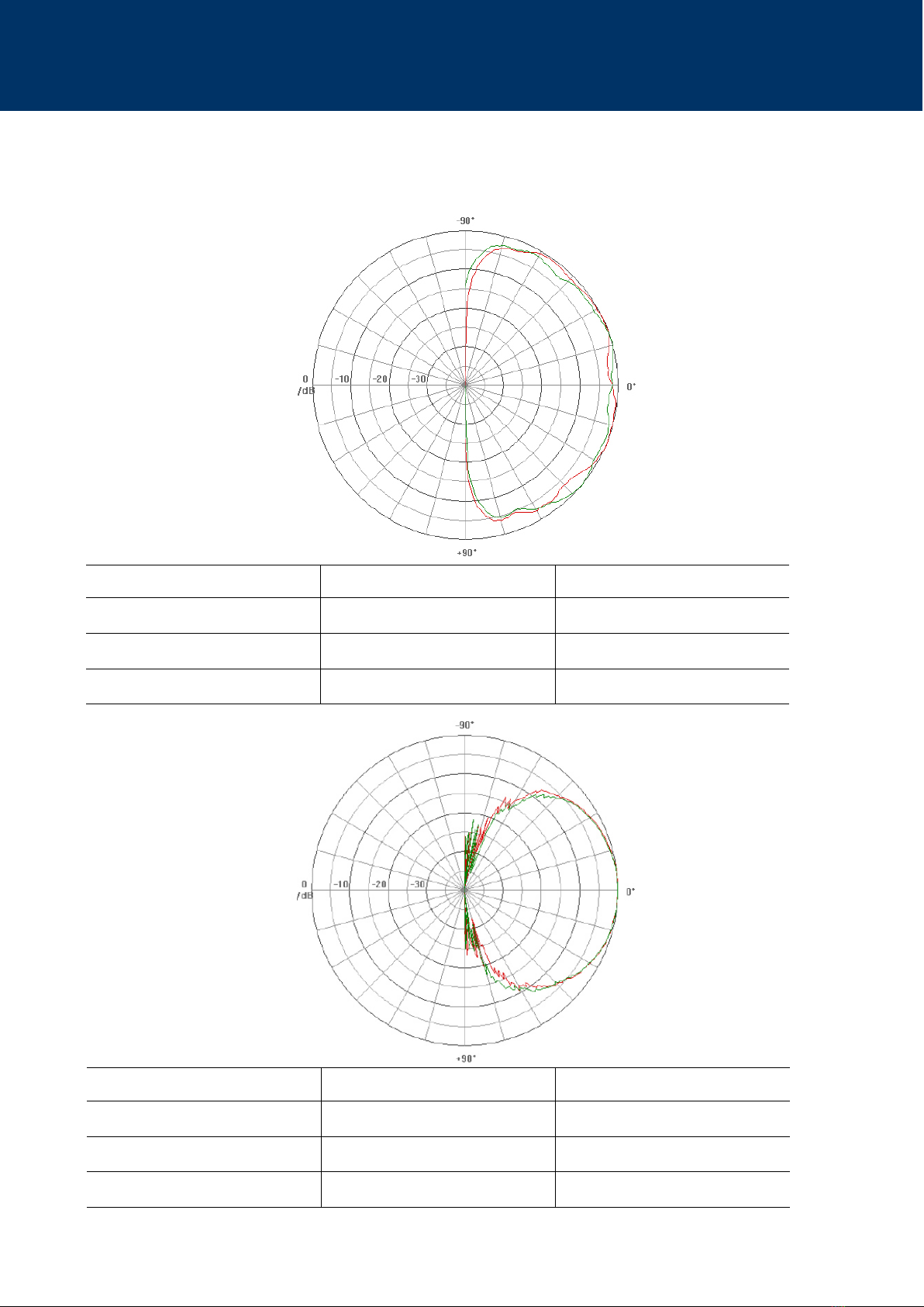
2.2 Antenna Paern
Red graph elevaon angle Green graph elevaon angle
TX antenna paern TX 1_Elevaon TX 2_Elevaon
3 dB—Width [°] 67 66
10 dB—Width [°] 110 111
Red graph azimuth angle Green graph azimuth angle
TX antenna paern TX 1_Azimuth TX 2_Azimuth
3 dB—Width [°] 135 137
10 dB—Width [°] 169 170

Rely on more Senses - www.innosent.de | 9
iSYS-5005 User Manual
Accessory Ordering Number Picture Descripon
Sensor The sensor consists of a Radar Front End
(RFE) with a DSP board. This is also the
series product.
Interface Board The Interface-Board is screwed onto the
underside of the sensor. There is a micro-
USB interface on it.
Radome The iSYS-5005 Evaluaon kit is supplied
with a radome. This can be considered as
a design recommendaon.
Soware
Package
can be downloaded from
InnoSenTs’ download
Server.
The soware package of the iSYS-5005
Evaluaon Kit includes:
Object Viewer soware
Radar API
Firmware Update
3. SCOPE OF DELIVERY
The scope of delivery of the iSYS-5005 Evaluaon Kit includes the following items.
The series product iSYS-5005 consists only of the RFE with DSP-Board.

Rely on more Senses - www.innosent.de | 10
iSYS-5005 User Manual
4. MECHANICAL DRAWING
The illustraons show the mechanical drawings of the iSYS-5005 as a series product.
Fig. 2: Mechanical drawing frontside iSYS-5005 series product
Fig. 3: Mechanical drawing backside iSYS-5005 series product
All dimensions in mm

Rely on more Senses - www.innosent.de | 11
iSYS-5005 User Manual
5. SAFETY INSTRUCTIONS
Only skilled and instructed persons shall install and connect the devices.
Proper experience in working with mains voltage, electrical and electronic devices is required.
Do not connect the devices directly to mains voltage, instead use the voltage given in the manual.
Do not wire any connecons while power is applied to the device.
Ground the devices carefully to prevent electrical shock.
All connectors are pin-coded and t in only one posion.
Mount the devices carefully to prevent them from shiing or dropping.
Ensure adequate venlaon during operaon.
Use a shielding for the sensor if needed to protect against environmental condions (snow, rain, dust).
Vibraon, oscillaon or any kind of movement will reduce the sensor performance.
Rely on more Senses - www.innosent.de | 12
iSYS-5005 User Manual
6. QUICK START GUIDE
The rst installaon of the iSYS-5005 Evaluaon Kit is very quick and easy. In this secon you will nd a descripon of the
rst setup of the sensor in a very quick procedure. Informaon on detailed setup can be found from page 14 onwards.
1. Step: Install the Object Viewer Soware
The soware package can be downloaded from our website (hps://www.innosent.de/downloadportal/).
Open the setup le of the Object Viewer soware package (iSYS-5005 -> GUI -> Object Viewer_V1.xxx.exe) and follow
the instrucons of the installaon on your windows PC.
2. Step: Mount the iSYS-5005 sensor in a staonary posion for example on a tripod.
Align the sensor in one direcon.
The sensor is in the correct orientaon when the USB port on the Evaluaon Kit is at the
boom.
Pay aenon to the mounng angle.
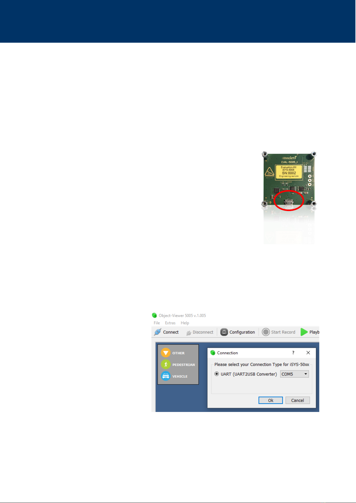
3. Step: Connect the iSYS-5005 via an USB cable (micro connector type B) to a PC.
The cable is not included in the Evaluaon Kit.
If both LEDs light up on the underside of the sensor, their connecon is successful.
4. Step: Open the installed Object Viewer Soware on your PC.
Press the Connect-Buon in the top le corner.
Select a connecon type to the iSYS-5005 Evaluaon Kit. Usually via UART/USB.
Fig. 4: Object Viewer Connect iSYS-5005
Rely on more Senses - www.innosent.de | 13
iSYS-5005 User Manual
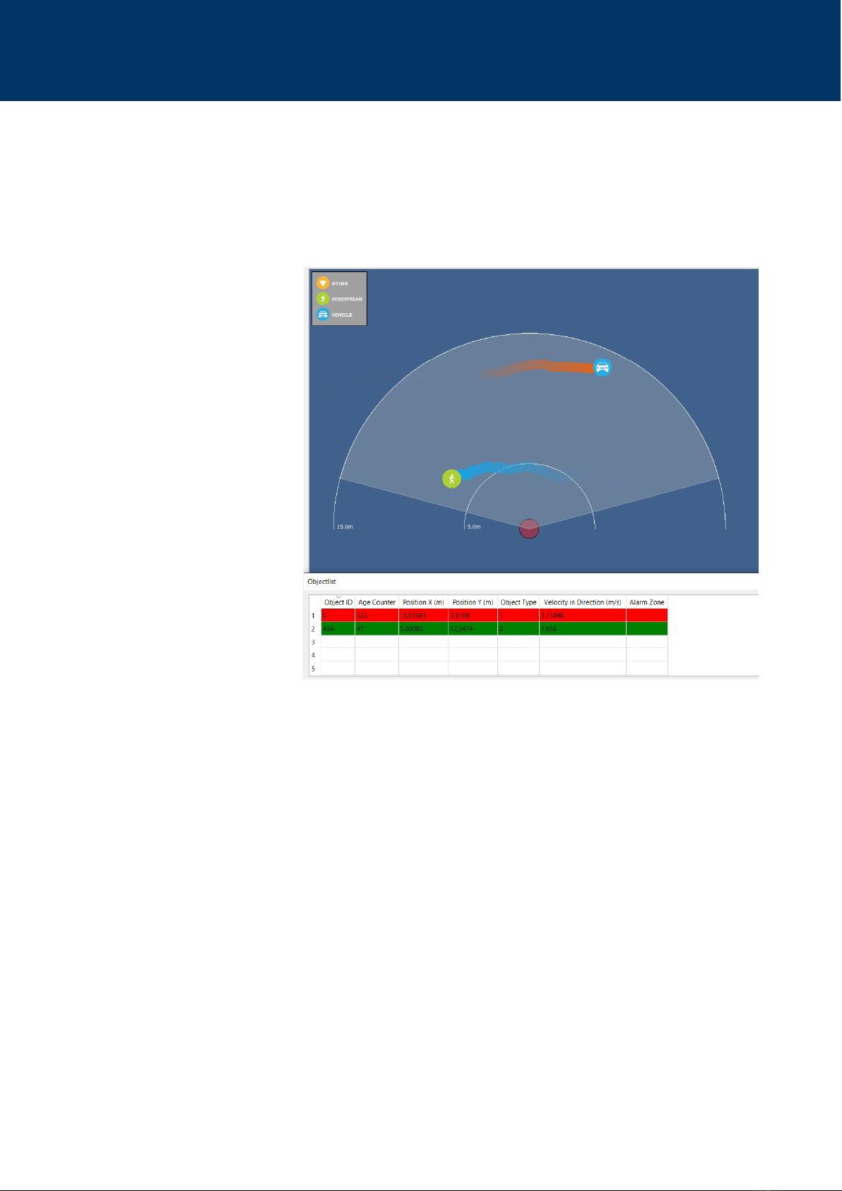
5. Step: Aer the connecon has been successfully established, the iSYS-5005 can recognize objects and create tracks.
The sensor is in mode A by default, you can switch to mode B on the right edge of the window.
Detailed informaon about an object such as ID, velocity, posion is displayed in the object list in the lower area of
the soware.
6. Step: Congratulaons! You have just started your iSYS-5005 Evaluaon Kit Sensor System.
The easy installaon is one smart feature of the iSYS-5005 Evaluaon Kit. The Object Viewer Soware enables a quick cong-
uraon of all necessary parameters. For more informaon on advanced seng opons such as seng individual zones see
the following pages.
Fig. 5: Object Viewer Soware with tracked objects
Rely on more Senses - www.innosent.de | 14
iSYS-5005 User Manual
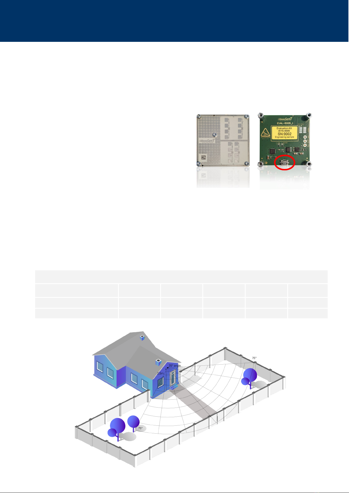
7. INSTALLATION AND ORIENTATION OF THE SENSOR
These gures show a typical installaon of the iSYS-5005 in a security and door opener applicaon and the right orientaon
of the sensor. Take care that the area of interest ts into the Field of View of the device. The iSYS-5005 is used to idenfy and
track moving, approaching and passing objects. The values in the tables given below for the installaon height and the
mounng angle are to be regarded as a tested recommendaon.
Security applicaon
installaon symbol min. typ. max. unit
height h2.3/7.5 2.5/8.2 2.7/8.8 m/
mounng angle α-35 °
Fig. 6: Typical security applicaon
7.1. Recommended Installaon Height and Mounng Angle
The installaon height recommended by us and the mounng angle are to be considered as recommendaons. These have
been tested in our factory. Diering installaons can aect the specied eld of view of the sensor. Individual installaon
heights and mounng angles must be evaluated by the customer himself.
Please note: The range depends on the respecve assembly in terms of height and angular orientaon.
The sensor is in the correct orientaon when the USB port on the
Evaluaon Kit is at the boom.
The correct orientaon of the series product of the iSYS-5005 is
based on the front of the illustraon on the right.
In this orientaon, the Field of View of ±75° in azimuth and ±30° in
elevaon is guaranteed.
Front of the
series product.
Back of the
Evaluaon Kit.

Rely on more Senses - www.innosent.de | 15
iSYS-5005 User Manual
Door opener applicaon
installaon symbol min. typ. max. unit
height h2.0/6.5 2.1/6.8 2.5/8.2 m/
mounng angle α-40 -45 -50 °
Fig. 7: Typical door opener applicaon

Rely on more Senses - www.innosent.de | 16
iSYS-5005 User Manual
8. CONNECTION
The iSYS-5005 Evaluaon Kit is connected with a micro USB port on the side of the Eval-Board as a customer interface (USB
cable is not included).
Pin # DESCRIPTION COMMENT
1UART_TX UART -> command interface (module side view)
2VCC 3.3 V—5.5 V supply voltage
3UART_RX UART -> command interface (module side view)
4GND
5DNC Do not connect
6DNC Do not connect
7DNC Do not connect
8DNC Do not connect
9DNC Do not connect
10 DNC Do not connect
8.2. Power supply
PARAMETER SYMBOL MIN TYP MAX UNITS
Suppy voltage VCC 3.3 5.5 V
Supply current ICC 330 mA
8.1. Connector Placement
The iSYS-5005 as a series product provides a 5x2, 1.27mm pitch Pin header. This connector (W+P 46-7072-010-20-00-00) is
mounted on the module facing backwards. InnoSenT uses a gold plated connector. A compable female pin header is W+P
46-6060-010-46-XX-XX-XX. The pin descripon and orientaon is given below.
Fig. 8: Connector placement iSYS-5005

Rely on more Senses - www.innosent.de | 17
iSYS-5005 User Manual
9. COMMUNICATION
The iSYS-5005 uses a UART protocol with a bitrate of 1MBaud.
It can easily be congured with the supplied Object Viewer soware or the iSYS5005_radarAPI.dll.
The dll is pre-compiled for dierent compilers and comes with an example project for easy integraon.
The sensor’s available commands can be found in the accompanying iSYS-5005_RadarAPI_readMe.pdf.
Read object list
Read conguraon data
Write conguraon data
iSYS-5005 Customer PC
9.1. Read/Write Conguraon
For a proper signal processing, the conguraon must be set carefully:
Set the mode rst
Set alarm and ignore zones
Set sensivity
It is recommended to congure the system with InnoSenT’s Object Viewer soware. This way conguraon data can easily
be wrien to the system. The conguraon is explained in secon [10].
The conguraon data can also be manually set by using iSYS-5005 Radar API. This library includes all funcons for communi-
caon with InnoSenT systems.

Rely on more Senses - www.innosent.de | 18
iSYS-5005 User Manual
9.2. Object List
Object list informaon:
Object ID: Unique ID the Tracker assigns to a Track
AgeCount: Number of frames the Track is alive aer being released.
Object Type (01 = pedestrain, 02 = vehicles, 03 = other)
Alarm Zone Index: Index of the Alarm Zone the Track is currently occupying. If the Track is in no Zone, the Index is
negave. (-2 if Track is outside of Zone or –1 if Zone is inacve). Zones start with index Zero.
Posion x (m): Distance the Track has to the sensor in X direcon (Cartesian coordinates), measured in meters.
Posion y (m): Distance the Track has to the sensor in Y direcon (Cartesian coordinates), measured in meters.
Velocity in direcon (m/s): Velocity the Track has in its direcon, measured in meter per second.
Direcon x: Direcon the Track has in X direcon (Cartesian coordinates), normalized to one.
Direcon y: Direcon the Track has in Y direcon (Cartesian coordinates), normalized to one.
Field of View: Indicates whether the track is in the specied eld of view.
Wind lter: Indicates whether an exisng track is within the specied wind lter specicaons.
Object lists are sent when requested by Radar API. InnoSenT’s Object Viewer soware provides an easy way of displaying the
received object lists.

Rely on more Senses - www.innosent.de | 19
iSYS-5005 User Manual
10. CONFIGURATION USING OBJECT VIEWER
The Object Viewer is the primary soware soluon to congure the iSYS-5005 Evaluaon Kit for use in the eld.
10.1. Installaon of Object Viewer
The Object Viewer can only be installed on a Windows PC. The setup les can be found in the device’s soware package or
downloaded on our website (hps://www.innosent.de/downloadportal/). Please ask your InnoSenT contact for informaon
on how to receive the soware package.
Open the Object Viewer folder in the soware package and install Object Viewer5005_Vx_xxx.exe (x_xxx = soware
version).
Follow the instrucons on the screen.
Click Finish to close setup and launch the Object Viewer.
Fig. 9: Installaon process Object Viewer Soware
10.2. Launch Object Viewer
Click on the Object Viewer icon to launch the soware.
When you start the object display soware, it is checked whether a soware update is available (prerequisite is an
acve Internet connecon).

Rely on more Senses - www.innosent.de | 20
iSYS-5005 User Manual
10.3. Overview of Object Viewer
InnoSenT’s Object Viewer is a soware soluon to congure your iSYS-5005 when installed in the eld and visualize the data
output from the system. The most important features of the Object Viewer are highlighted below. The Object Viewer is in-
tended for visualizing the tracked data obtained from the sensor and simplies the evaluaon of the system.
10.4. Connect to Network Camera (if available)
It is recommended to set up a network camera together with the iSYS-5005. With
the video from the network camera a remote vericaon of the displayed radar
data is much easier. In ‘Record Mode’ the video stream from the camera is stored
together with the radar data on the hard disk. Therefore, it is possible to evaluate
data oine.
Note: It is important to connect to the network camera before connecng to the
iSYS-5005. Select your camera in Object Viewer ’Camera’ drop down menu to add
and connect. A video stream will appear when the camera is turned on and a con-
necon is established.
Object classicaon
Object list from iSYS-
5005
Connect or disconnect
Conguraon
Wizard to congure
Add network camera
and display video
stream
Sensor Informaon
Change view sengs
Select device mode
Record & Playback
object list with video
stream
Display background
image, zones and
tracked objects (main
window)
Read Conguraon
from System
Send Conguraon
to System
Fig. 10: Overview Object Viewer
Fig. 11: Add Camera Object Viewer
Table of contents


