Innotech VERT-SET-50 User manual
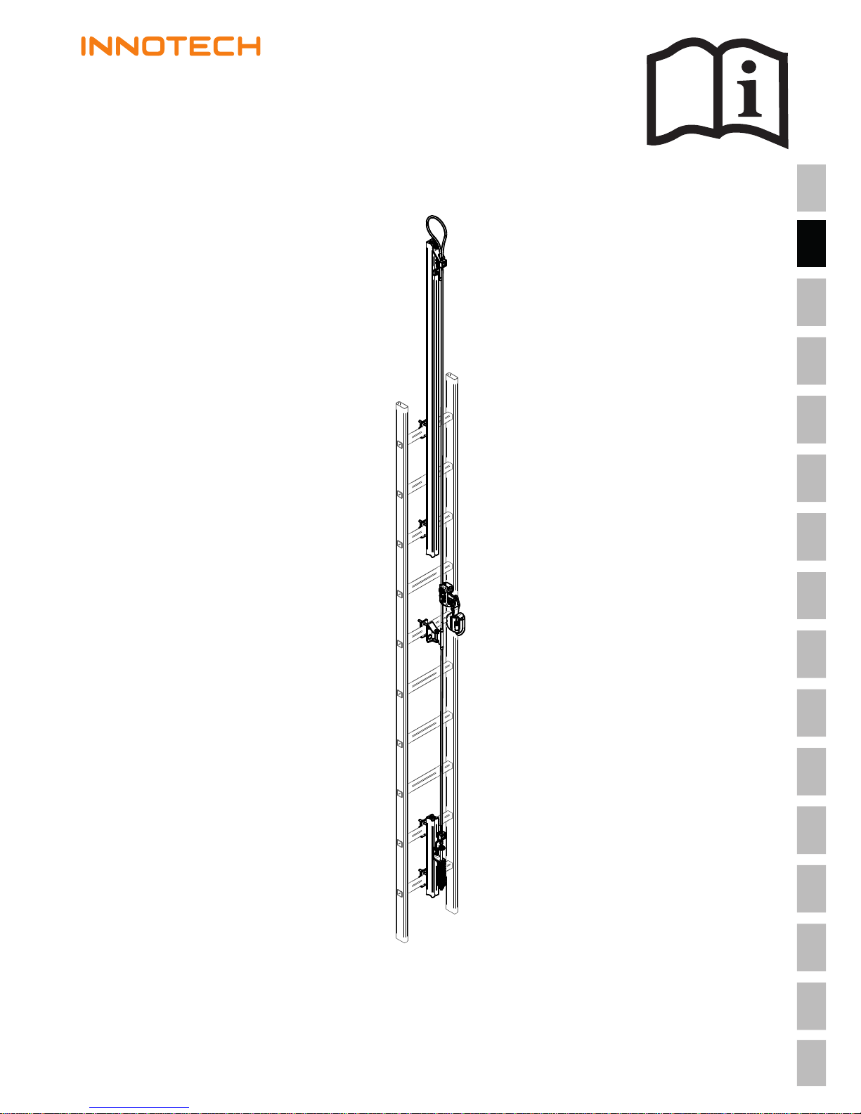
VERT-SET-50
Instruction manual
© INNOTECH Arbeitsschutz GmbH. Irrtümer, Druckfehler, technische Änderungen vorbehalten!
© INNOTECH Arbeitsschutz GmbH. Errors and misprints accepted. We reserve the right to make technical changes.
DE – ACHTUNG: Die Verwendung des INNOTECH-Produkts ist erst zulässig, nachdem die
Gebrauchsanleitung in der jeweiligen Landessprache vollständig gelesen und verstanden wurde.
DE
EN – ATTENTION: Use of the INNOTECH product is only permitted after the instruction
manual has been read and fully understood in the respective language.
EN
IT – ATTENZIONE: L'utilizzo del prodotto INNOTECH è permesso solo previa lettura e
comprensione dell'intero manuale di istruzioni nella lingua del relativo paese di utilizzo.
IT
FR – ATTENTION : L'utilisation du produit INNOTECH n'est autorisée qu'après avoir
entièrement lu et compris la notice d'utilisation dans la langue du pays concerné.
FR
NL – ATTENTIE: Dit INNOTECH-product mag pas gebruikt worden nadat u de gebrui-
kershandleiding in de taal van het betreffende land gelezen en begrepen hebt.
NL
SV – O B S : Denna INNOTECH-produkt får inte användas förrän bruksanvisningen på
respektive lands språk har lästs igenom och förståtts.
SV
DK – GIV AGT: Du må først bruge et produkt fra Innotech, efter du har læst og forstået
brugsvejledningen i fuldt omfang i dit lands sprog.
DK
ES – ATENCIÓN: Se autorizará el uso de los productos INNOTECH una vez que se hayan
leído y entendido las instrucciones de uso en el idioma del país.
ES
PT – ATENÇÃO: O uso do produto INNOTECH apenas é permitido depois de ter lido e
compreendido na totalidade as instruções de uso na respetiva língua nacional.
PT
PL – UWAGA: Produkty firmy INNOTECH mogą być używane dopiero po dokładnym
zapoznaniu się z całą instrukcją obsługi w ojczystym języku.
PL
TR – DİKKAT: INNOTECH ürününün kullanımına ancak ilgili ülkenin dilinde sunulmuş
olan kullanım kılavuzunun tamamen okunmasından ve anlaşılmasından sonra izin verilir.
TR
SL – POZOR: Uporaba izdelka INNOTECH je dovoljena šele po tem, ko ste navodila pre-
brali v celoti v ustreznem jeziku svoje dežele in jih tudi razumeli.
SL
CZ – POZOR: Práce s výrobkem INNOTECH je povolena teprve po kompletním přečtení a
porozumění návodu k použití v jazyku daného státu.
CZ
SK – POZOR: Produkt INNOTECH môžete používať až po prečítaní a porozumení celého
návodu na použitie pre príslušnú krajinu.
SK
HU – FIGYELEM: Az INNOTECH termékek használata csak azt követően engedélyezett,
hogy saját nyelvén elolvasta és megértette a teljes használati utasítást.
HU
ZH – 注意:只有在仔细阅读并完全理解了当地语言的使用说明后,才能使用 INNOTECH 公司的产品。
ZH

2
VERT-SET-50 / Version 170201 / www.innotech.at
EN
1TABLE OF CONTENTS
[2] SYMBOL DESCRIPTION 3
[3] SAFETY INSTRUCTIONS 4
[4] COMPONENTS/MATERIAL 6
[5] PRODUCT APPLICATION/APPROVAL 7
[6] INSPECTION 8
[7] GUARANTEE 9
[8] SIGNS & MARKINGS 10
[9] DIMENSIONS 11
[10] INSTALLATION NOTICE 13
[11] INSTALLATION SUBSTRUCTURE 13
[12] FASTENING OPTIONS 14
[13] INSTALLATION TOOLS 14
[14] INSTALLATION 15
[15] DISPOSAL 20
[16] ACCEPTANCE REPORT 21
[17] SAFETY SYSTEM NOTICE 22
[18] TESTING REPORT 23
[19] DEVELOPMENT & SALES 25
3
EN
VERT-SET-50 / Version 170201 / www.innotech.at
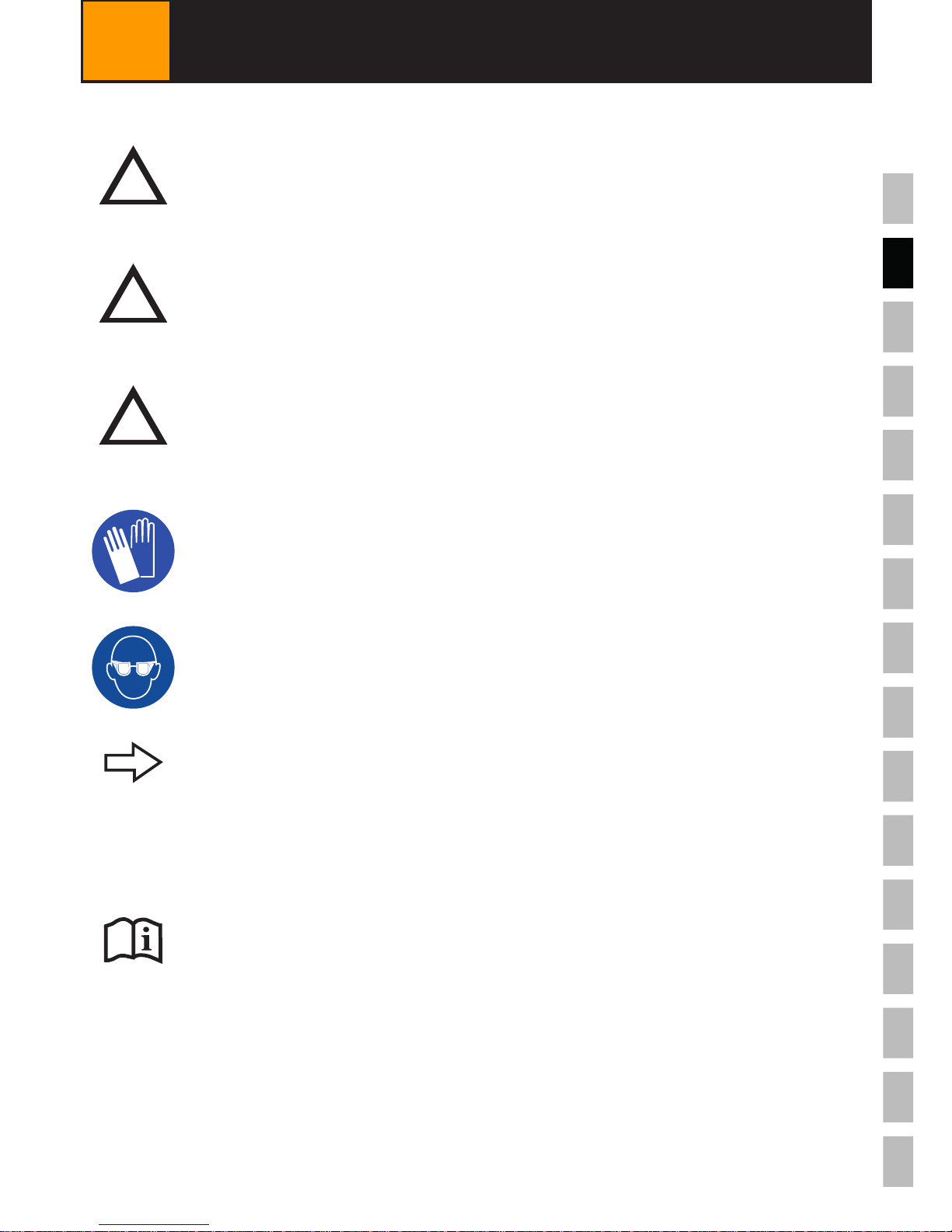
2SYMBOL DESCRIPTION
Additional Information/Instructions
Warning/Danger Notications
For an IMMEDIATE potential danger which could lead to serious injury
or death.
ücorrect incorrect
For a POTENTIALLY dangerous situation which could lead to serious injury
or death.
For a POTENTIALLY dangerous situation which could lead to minor injury
or property damages
!
DANGER
!
WARNING
CAUTION
!
Follow the manufacturer's instructions / appropriate user manuals
Wear protective gloves!
Wear protective glasses!

4
VERT-SET-50 / Version 170201 / www.innotech.at
EN
3SAFETY INSTRUCTIONS
3.1 GENERAL
The following safety instructions and the latest technical developments must be
taken into account.
-The safety system may only be assembled by competent, qualied persons who are
familiar with the safety system. It may only be assembled in accordance with the
latest technical developments.
- The protective equipment may only be used by persons who:
• have been trained to use "Personal Protective Equipment" (PPE).
• are physically and psychologically sound. Health restrictions such as
cardiovascular problems, medication use, alcohol consumption, etc.
decrease user safety.
• are familiar with the locally applicable safety rules.
- During assembly / use of the safety system, the applicable accident prevention regu-
lations (e.g. for work on roofs) must be observed, as well as the rules and norms for
the use of personal protective equipment for fall prevention.
- The possibilities, limits and risks when using the protective equipment must be
understood and accepted.
- A plan must be in place that includes lifesaving measures for all possible emergenci-
es (e.g. at least two INNOTECH "VERT-GLEIT-50‟, ...).
- Before beginning work, measures must be taken to ensure that no objects can fall
down from the working area. The area under the working area (sidewalk, etc.) must
be kept clear.
- Every safety system is subject to maximal load limits. These are visible on the serial
plate of the safety system and must not be exceeded.
- The serial plate of the safety system must be posted in a place which is visible for
the user.
- Should any renovation work be done in the immediate vicinity of the safety system
after receipt of the system, it must be veried that this work has no impact on the
safety provided by the installed system! In case of doubt, a structural engineer or
the manufacturer should be consulted.
- After stress on the system from a fall, the entire safety system must be taken out
of operation and tested by a qualied professional (component parts, anchors to the
substructure, etc.).
- If use of the safety system is to be allowed to external contractors, their understan-
ding of these user instructions is to be conrmed in writing.
- In case of non-natural environmental conditions (e.g. chemical substances) the
manufacturer must be consulted.
-The safety system is not to be modied in any way.

5
EN
VERT-SET-50 / Version 170201 / www.innotech.at
3SAFETY INSTRUCTIONS
3.2 FOR INSTALLERS: FOR SAFE INSTALLATION
3.3 FOR USERS: FOR SAFE USE
Should anything be unclear during the installation process, it is imperative
that the manufacturer be contacted.
- If the equipment is sold to an organization in another country, the user instructions
must be made available in the local language.
- The lightning protection regulations of the country must be followed.
- All stainless steel screws are to be lubricated with appropriate lubricant before
installation (included: Weicon AntiSeize ASW 10000 or equivalent).
- Stainless steel may not come into contact with sander dust or steel tools. This leads
to corrosion.
- The appropriate attachment of the safety system to the construction must be docu-
mented with anchor logs and photos of the circumstances of installation.
- The installers must ensure that the substructure is appropriate for the anchoring of
the INNOTECH "VERT-SET-50" safety system. In case of doubt, consult a structural
engineer.
- It is also essential that the mounting ladder on which the safety system is installed
is suciently stable.
- To ensure safe entry / mounting of the safety system all necessary work safety
regulations are to be observed.
-Because there is a danger of ground contact over the rst 2 m, one must be especi-
ally cautious when getting on and o of the system.
- The minimum spacing between 2 persons on the safety system is 3 m (measured
from the feet of the upper person to the head of the lower person).
- If there is a risk of ice buildup, it is necessary to check for it constant monitoring of
the INNOTECH "VERT-GLEIT-50‟ spring-loaded eccentric lever. The stainless steel
cable must also be checked to ensure that it is free of ice.
- The individual elements, including the "Personal Protective Equipment" must be used
appropriately, since the protective function of the safety system is otherwise NOT
provided.
- In case of unusually strong winds, the safety system must NOT be used.
-Children and pregnant women should NOT use the safety system.
6
VERT-SET-50 / Version 170201 / www.innotech.at
EN
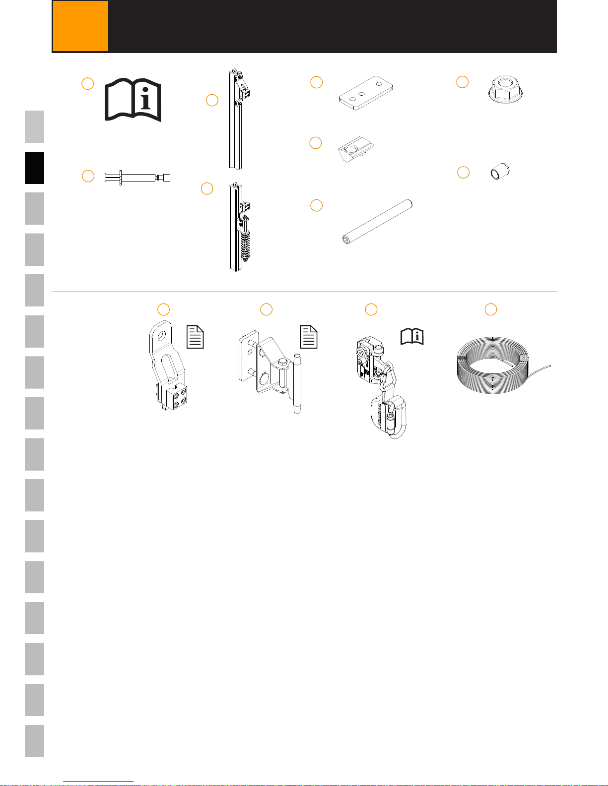
4COMPONENTS /MATERIAL
A) User Manual
B) Lubricant: Weicon AntiSeize ASW10000
C) "VERT-SET-50" Top anchor: Stainless steel AISI 304; Aluminium 6063
D) "VERT-SET-50" Bottom anchor: Stainless steel AISI 304; Aluminium 6063
E) "VERT-SET-50" Clamp plate: Stainless steel AISI 304
F) "VERT-SET-50" Slot nut: Stainless steel AISI 304
G) Set screw M8x80: Stainless steel AISI 304
H) Hex nut M8: Stainless steel AISI 304
I) End cap: PVC
OPTIONAL:
J) "VERT-SAFE-50" Backup anchor: Aluminium 6060, Stainless steel AISI 304
Not included in standard set!
K) "VERT-SZH-50": Stainless steel AISI 304
Not included in standard set!
L) "VERT-GLEIT-50": Stainless steel AISI 304/316
Not included in standard set!
M) "AIO-SEIL-30" Stainless steel cable: Stainless steel AISI 316
Not included in standard set!
A
B
C
D
E
F
G
H
I
JK
4x
8x
8x
8x
2x
L
OPTIONAL: M
7
VERT-SET-50 / Version 170201 / www.innotech.at
EN
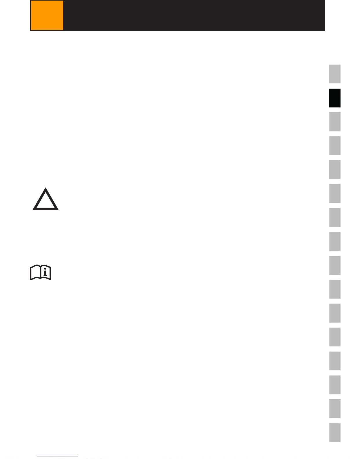
5
PRODUCTAPPLICATION/APPROVAL
INNOTECH "VERT-SET-50‟ was developed as a Climbing protection apparatus for
personal safety for 2 persons (1 person per slider).
INNOTECH "VERT-SET-50‟ is intended for use while roping up with personal protective
equipment to provide safety while climbing up and down ladders.
The user is connected to the safety system by a body harness in accordance with EN
361, as well as by the INNOTECH "VERT-GLEIT-50‟ vertical glider. In order to minimise
the fall stress for the user, the INNOTECH "VERT-GLEIT-50‟ is equipped with a shock
absorber.
Maximum total weight allowance: 50 to 130 kg (incl. clothing + equipment)
Follow the manufacturer's instructions for the personal protective
equipment used.
MORTAL DANGER in case of incorrect use.
- INNOTECH "VERT-SET-50‟ ONLY to be used in conjuction with personal
protective equipment.
- INNOTECH "VERT-SET-50‟ NOT to be used for workplace positioning.
-NEVER hang loads on the INNOTECH "VERT-SET-50‟, which are NOT
approved of in this user manual.
!
DANGER
INNOTECH "VERT-SET-50‟ has been tested and certied according to EN 353-1:2014
Notified bureau for type examination:
TÜV Austria Services GmbH, Deutschstrasse 10, A - 1230 Vienna / Austria

8
VERT-SET-50 / Version 170201 / www.innotech.at
EN
6.1 INSPECT BEFORE EACH USE
6INSPECTION
DANGER OF DEATH from damage to
INNOTECH "VERT-SET-50".
- INNOTECH "VERT-SET-50‟ must be in awless condition.
- INNOTECH "VERT-SET-50‟ must be free of dirt and grease.
- INNOTECH "VERT-SET-50‟ IS NOT to be used if :
• Visible damage or wear can be seen on the components,
• other flaws have been identified (loose screw connections,
deformation, corrosion, wear, etc),
• the stress of a fall has been exerted on the construction
(exception: rst aid administration), (check the spring length before
each use!)
• the product designation is illegible.
!
DANGER
INNOTECH "VERT-SET-50‟ is to be checked visually before each use for visible aws.
The useability of the entire safety system must be conrmed through the acceptance
and inspection reports.
In case of doubt regarding the safe functioning of the safety system,
take it out of service and have it tested by a competent professional
(with written conrmation).
Replace the product if needed.
Follow the user manual of the vertical glider used ("VERT-GLEIT-50‟).

9
EN
VERT-SET-50 / Version 170201 / www.innotech.at
Follow the testing intervals found in the inspection log.
6.2 ANNUAL INSPECTION
Have the INNOTECH "VERT-SET-50‟ examined at least once annually by an experienced
professional who is familiar with the safety system. The safety of the user is dependent
upon the eectiveness and durability of the equipment.
Depending upon the intensity of use and the environment, shorter examination intervals
can be necessary (e.g. in case of corrosive atmosphere, etc.).
The qualied professional's examination is to be documented in the testing log included
in the user manual and kept on record with the user manual.
6INSPECTION
All components are guaranteed against manufacturing aws for 2 years from the date of
purchase (under normal conditions of use). The period is shortened when components
are used in corrosive atmospheres.
In case of a stress on the system (fall, snow load, etc.) the guarantee covering compo-
nents which were designed to absorb energy or which were deformed is void.
For system installation and for components which are planned and
installed by professional installation rms under their own responsi-
bility; INNOTECH® takes no responsibility and oers no guarantee in
case of improper installation.
7GUARANTEE
10
VERT-SET-50 / Version 170201 / www.innotech.at
EN
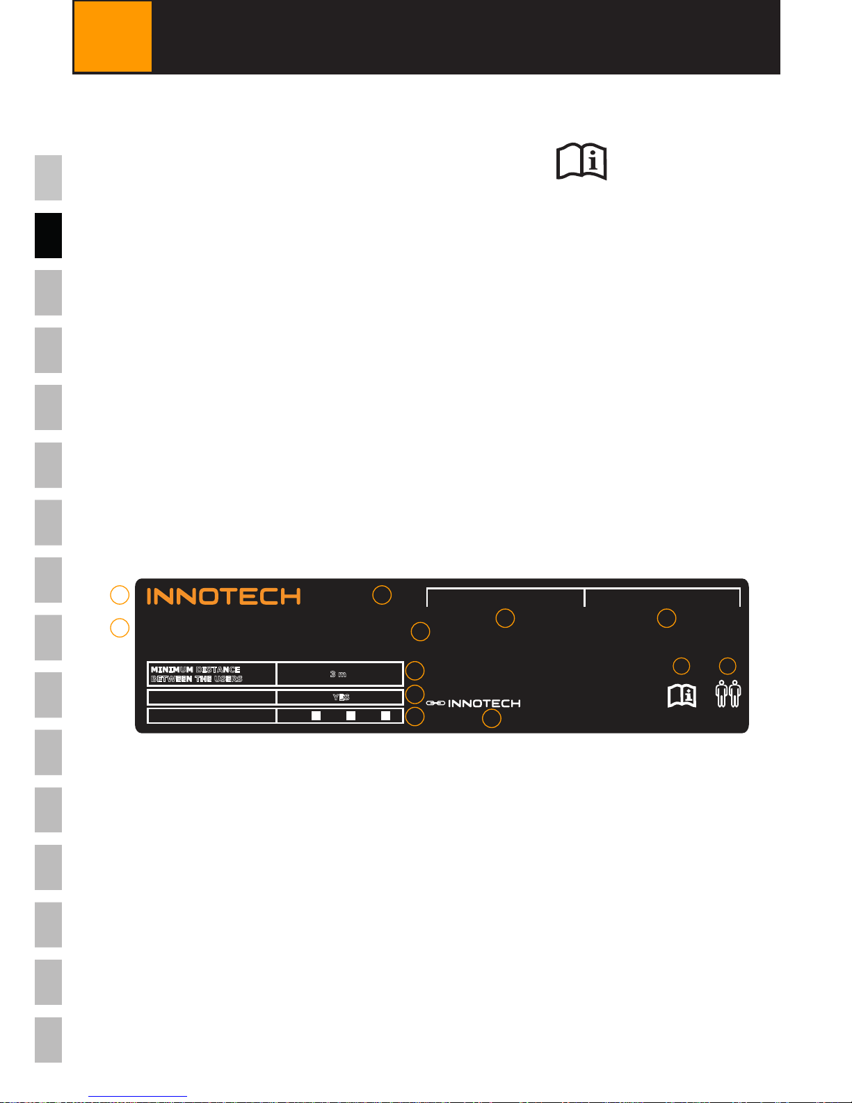
8SIGNS & MARKINGS
A) Name or logo of the manufacturer/seller: INNOTECH
B) Type designation: VERT-SET-50
C) Sign that the user instructions must be
followed:
D) Maximum number of persons to be fastened: 2 (incl. 1 person for
rst aid administration)
E) CE-Conformity designation: C 0408
F) Year of manufacture and manufacturer's
serial number: JJJJ-..-...
G) Number of the applicable norm: EN 353-1:2014
H) Minimum distance between users: 3 m
I) Shock absorber: YES
J) Installation date: Year of installation: ý
K) Date of the next annual examination: Annual maintenance
L) Name & address of installation company: Installed by
VERT-SET-50
ANNUAL MAINTENANCE
INSTALLED BY
06-06-50-AUFKLEBER-EN-B
0408
JJJJ-..-...
VERT-GLEIT-50
max.
FALL BREAKER YES
INSTALLATION DATE 2016 2017 2018
MINIMUM DISTANCE
BETWEEN THE USERS
3 m
EN 353-1:2014
A
B
CD
E
F
G
H
I
J
KL
11
EN
VERT-SET-50 / Version 170201 / www.innotech.at
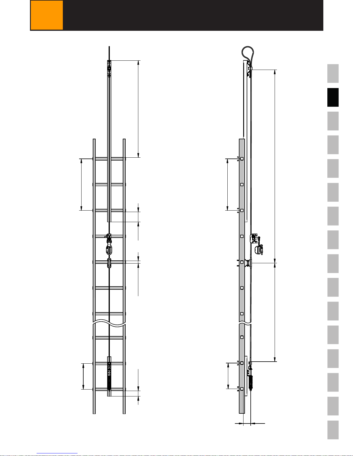
9DIMENSIONS
[mm]
≥
3 x
1050
≤≥
50
≤
q
45
≥
2 x
≤
350
≤
750
≤
5000
≤
5000
≥
50
80
12
VERT-SET-50 / Version 170201 / www.innotech.at
EN
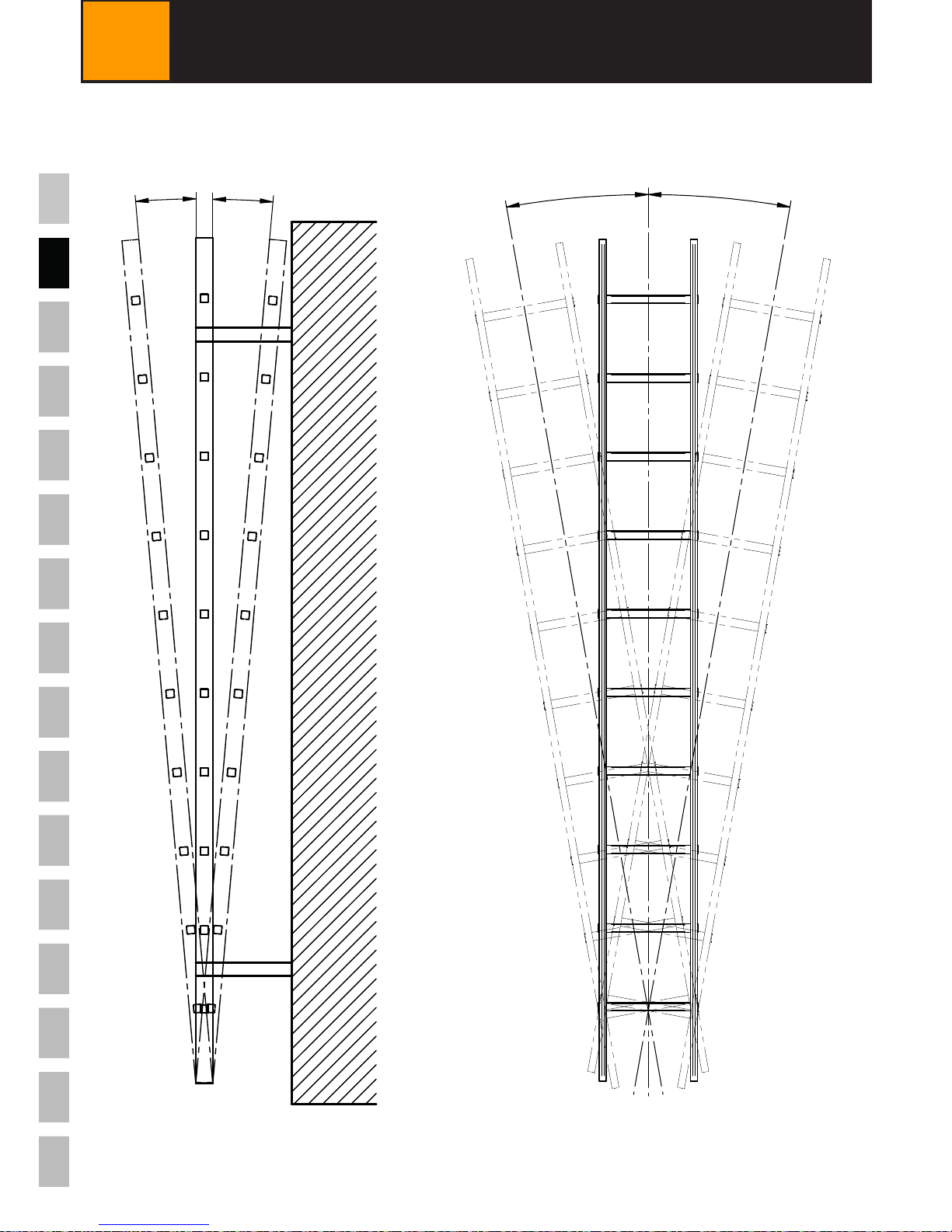
9DIMENSIONS
≤
3
v
≤
15
v
≤
15
v
≤
15
v

13
EN
VERT-SET-50 / Version 170201 / www.innotech.at
11 INSTALLATION SUBSTRUCTURE
The basic requirement for proper installation of the backup anchor for additional safety
on the construction is an appropriate installation substructure (concrete, steel, etc.) and
the use of the original connecting methods explained in this user manual.
Connection to the ladder
Few ladder rungs can bear the necessary force of 16 kN (as per EN 353-1).
The INNOTECH "VERT-SET-50‟ safety system can therefore be complemented by a
backup anchor for additional safety, "VERT-SAFE-50‟ (not included in standard set),
which allows for attachment to a static load-bearing construction.
When installed correctly, the INNOTECH "VERT-SET-50‟ provides force transmission of
more than 16 kN.
The stress on the user, e.g. during a fall, is reduced by the shock absorber strap. The
actual stress to be expected is approx. 5 kN.
10 INSTALLATION NOTICE
MORTAL DANGER when NOT installed properly.
!
DANGER
14
VERT-SET-50 / Version 170201 / www.innotech.at
EN
12 FASTENING OPTIONS
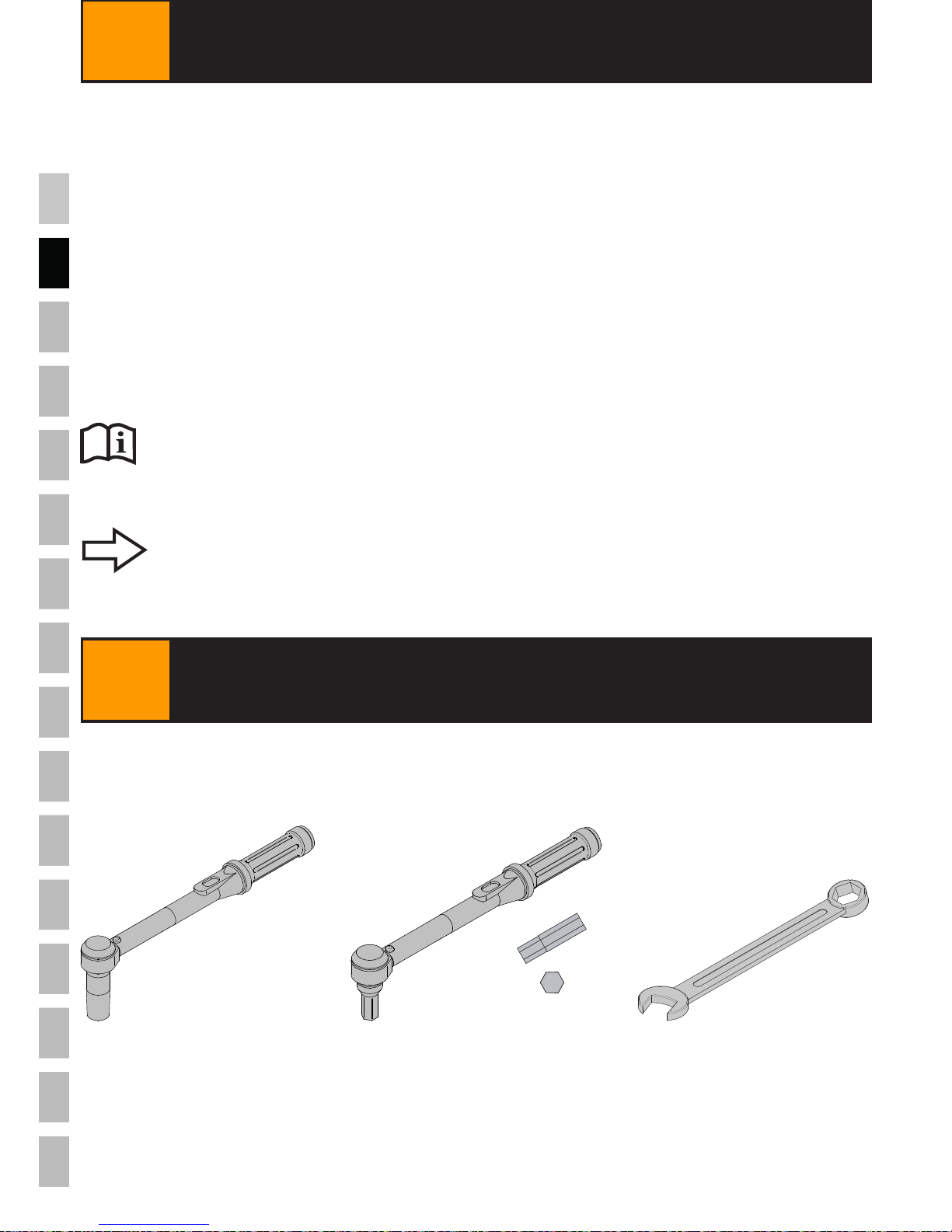
13 INSTALLATION TOOLS
[mm]
SW = 13 SW = 5 SW = 13
CONCRETE SUBSTRUCTURE:
-Threaded rod M12 with FISCHER FIS SB 390 S or Hilti HY 200 stuck
into concrete or
-Heavy-duty anchor, Fischer FAZ II 12/30.
STEEL SUBSTRUCTURE:
-Threaded bolt M16
Use products from other manufacturers only if their technical
specifications are equivalent (compare product data sheets).
The fastening elements mentioned here are NOT included.
Fastening opitons for the backup anchor for additional safety "VERT-SAFE-50‟ on the
construction:
2x
15
EN
VERT-SET-50 / Version 170201 / www.innotech.at
MORTAL DANGER if NOT assembled correctly.
-INNOTECH "VERT-SET-50‟ must be installed correctly according to the
user manual.
!
DANGER
EYE INJURY possible from dust/splinters/liquids.
- Wear eye protection/protective glasses for installation work.
CAUTION
!
14 INSTALLATION
CAUTION
!
INJURIES from sharp edges of components.
- Wear gloves for installation work.

16
VERT-SET-50 / Version 170201 / www.innotech.at
EN
Order the anchors, depending upon rung width, as closely together as
possible. Attach them at the desired position to the slot.
1.
2.
Order the anchors, depending upon rung width, as closely together as
possible. Attach them at the desired position to the slot.
14 INSTALLATION
14.1 "VERT-SET-50‟TOP FIXING & BOTTOM FIXING
41
M8
41
M8
[mm]
[mm]

17
x.
x.
VERT-SET-50 / Version 170201 / www.innotech.at
EN
Install the "VERT-SET-50‟ top anchor at the top end over at least 3 ladder
rungs (beginning with the top one) with a maximum spacing of 750 mm.
3.
14 INSTALLATION
4.
Observe tightening torque.
Observe tightening torque.
2 x 10 Nm
2 x 10 Nm
SW = 13
SW = 13
2 x 10 Nm
2 x 10 Nm
Install the "VERT-SET-50‟ bottom anchor over at least 2 ladder rungs
(beginning with the lowest) with a maximum spacing of 350 mm.
< 750
< 350
18
VERT-SET-50 / Version 170201 / www.innotech.at
EN
1.
2.
14 INSTALLATION
14.2 INNOTECH "VERT-SET-50‟STAINLESS STEEL CABLE
Observe tightening torque.
4 x 10 Nm
250 - 27070~
SW = 5

19
x.
x.
VERT-SET-50 / Version 170201 / www.innotech.at
EN
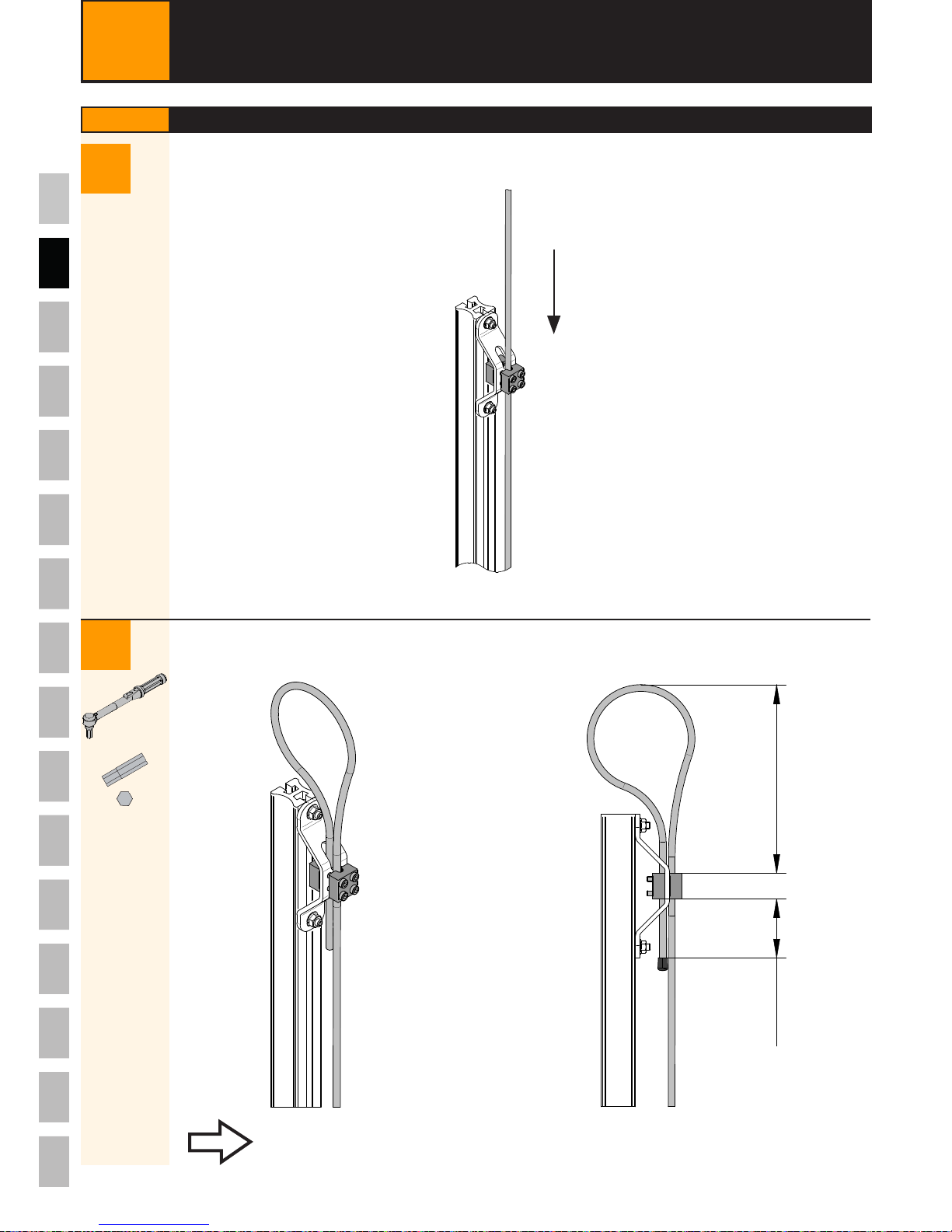
Shorten the bottom end of the stainless steel rope appropriately and screw
to tighten. Apply the end cap.
3.
14 INSTALLATION
4.
Observe tightening torque.
~ 20
Spring length
(after applying tension)
80 - 90 mm.
By checking the spring length, the possible fall load can be
determined before using the INNOTECH "VERT-SET-50‟ safety
system.
2x
4 x 10 Nm
SW = 5
80 - 90 mm
20
VERT-SET-50 / Version 170201 / www.innotech.at
EN
Do NOT dispose of the safety system with household waste.
Collect the used components according to national regulations and recycle them
appropriately.
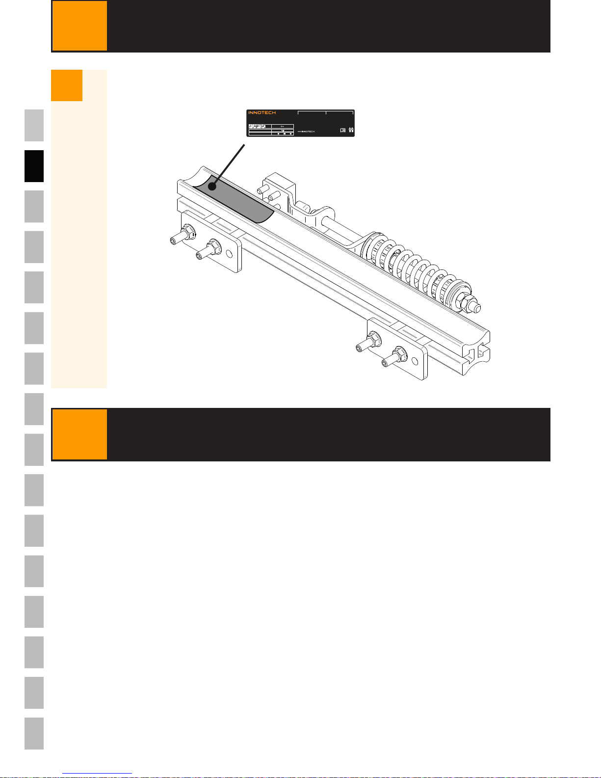
14 INSTALLATION
5.
VERT-SET-50
ANNUAL MAINTENANCE
INSTALLED BY
06-06-50-AUFKLEBER-EN-B
0408
JJJJ-..-...
VERT-GLEIT-50
max.
FALL BREAKER
YES
INSTALLATION DATE
2016 2017 2018
MINIMUM DISTANCE
BETWEEN THE USERS
3 m
EN 353-1:2014
15 DISPOSAL
Other manuals for VERT-SET-50
2
Table of contents
Other Innotech Cables And Connectors manuals


