2.3 Steamer Functions
6
English
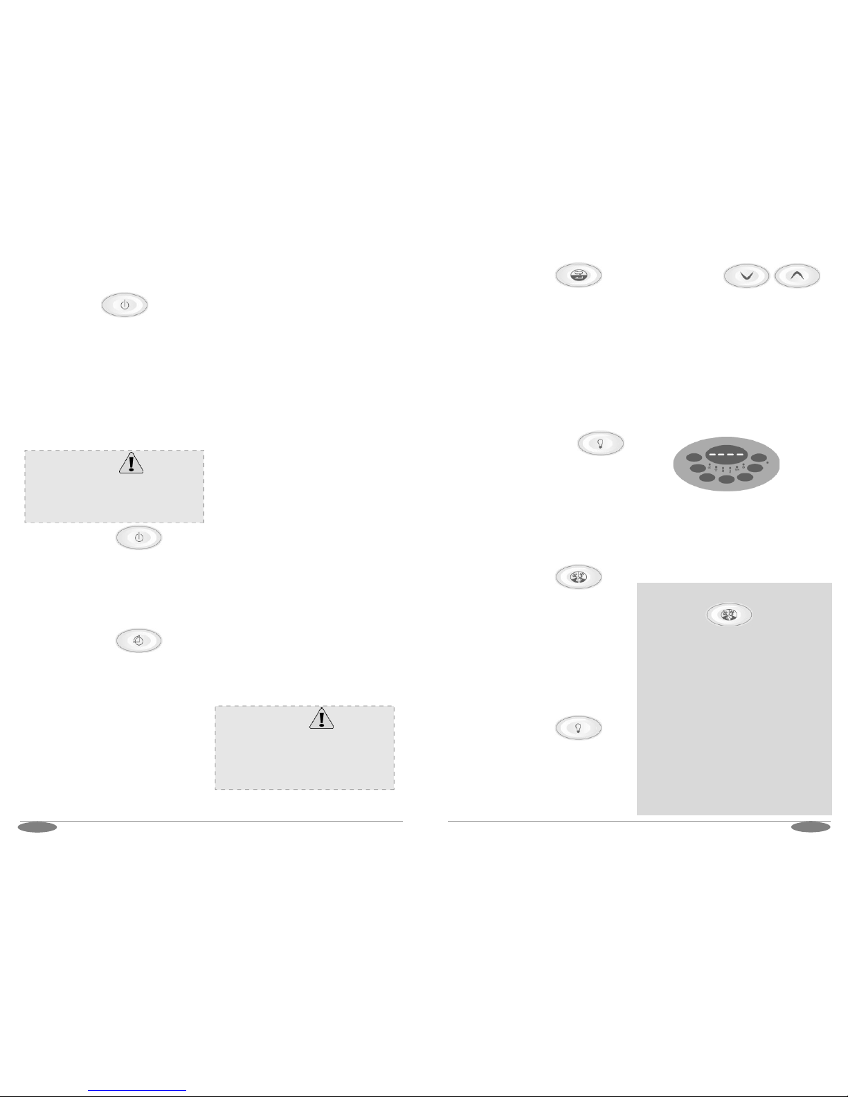
2.2.4 Setting Mode
Long press the toggle button to activate
setting mode. It can be used to select and
adjust the fan*, temperature, humidity* and
the session time (*not all models have all
the same features). Corresponding LEDs
will be blinking on each selected features.
Change values by pressing the up and down
buttons.
Save the settings by long pressing the
toggle button, a high beep will confirm it. If
no keys are pressed within 5 seconds, the
control unit will save the settings.
2.2.7 Cabin Light Button
Cabin light can be switched on, even when
the heater or pre-run timer are off. Short
press the button and the lights will be
switched on/off.
LED for the light indicates if the light is
switched on or off.
2.2.5 Dimmer light (optional)
When the lights are switched off, short
press the light button to activate the
dimmer.
If the lights are on and the cabin light
button is pressed for long, it will toggle the
dimmer light state. Then the cabin lights
can be adjusted with the arrow buttons
from 0% to 100%. Confirm the settings
with the toggle button.
The steamer function can only be activated
if the heater has a steamer and the steamer
feature is present on the controller. When
there is no steamer present, all the
functions and settings regarding the
steamer are not available.
Press the mode button for less than 3
seconds to activate the steamer. Once
activated, the steamer is switched on,
unless the temperature or the relative
humidity inside the sauna room is too high.
High humidity and high temperature are not
allowed, “HOT” will be displayed in the
control unit and the steamer will not be
activated.
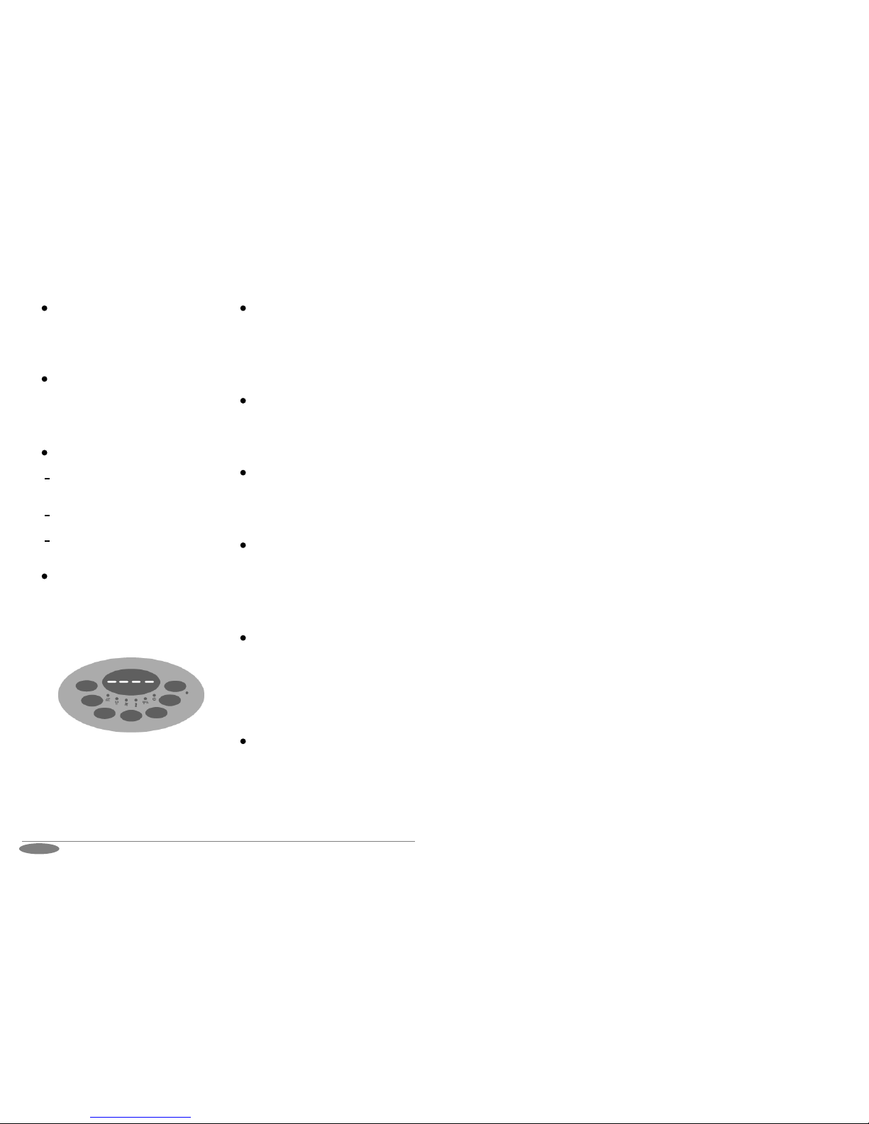
Lock the key pad by pressing the up and
down arrow keys at the same time for more
than 5 seconds. A high beep will confirm the
activation and the deactivation.
When key lock is activated only heater on/off
and cabin light functions can be used. Toggle
button is enabled only to see actual values. If
other buttons are pressed, “----“ is shown in
the display.
Unlock the buttons by pressing up and down
arrow keys at the same time for more than 5
seconds. A high beep will confirm it.
The key lock function is set automatically if it
was activated during the previous operation.
2.2.8 Key pad lock
(to prevent unauthorised use of
control unit)
2.3.1 Steamer
2.2.6 Fan (optional)
If the model installed has a fan, its speed
can be regulated. Switch it on or off by
pressing the mode button, LED light for fan
will indicate if the fan is turned on or off.
The speed of the fan can be set in the
settings mode.
Please note: If the used heater is a Combi
with a steamer, the button needs to be
pressed for longer than 3 seconds to
activate the fan. Long press it again to turn
off the fan.
5English
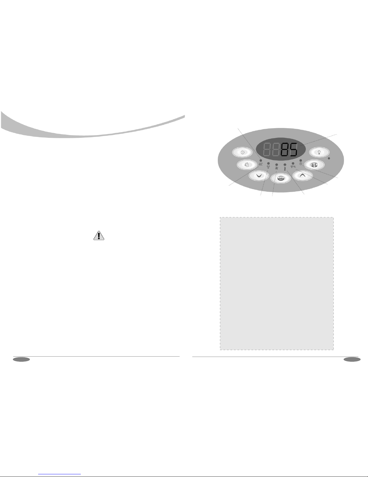
2.2.1 Heater on
Press the Power button to activate the
heater. The heater LED is illuminated
indicating that the heater is turned on.
The sauna will heat up to the temperature of
the previous setting and operate for the
length of previous session time. Session
time is saved for next session only if session
time is changed within 5 minutes after
switching the heater on.
2.2.2 Heater off
Turn the heater off by pressing the Power
button. This button will turn off all the active
functions, including the pre-run session.
However, the sauna room light will not be
switch off. Light button can be used even the
heater is off.
2.2 Directions of use
2.2.3 Pre-run button
Pre-run button is enabled only when the
heater is turned off. During the pre-run
parameter values can be changed.
Set the pre-run time by pressing the
pre-run button. Pre-run time will be
displayed indicating countdown time after
which the sauna is ready for use. The up
and down arrow keys can be used to change
the pre-run time.
Next, temperature, fan*, steamer* and
session time (*not in all models). can be
changed if preferred. Finally press the
toggle button for long to confirm.
When the control unit is in the pre-run state,
it will display the remaining time of the
pre-run. The confirmed pre-run settings are
saved for the next session.
When the pre-run function is used for the
first time control unit estimates the time that
the heater needs to reach the set tempera-
ture. For example, if the pre-run time is set
to 2 hours, the heater will be switched on in
1.5 hours.
If the sauna has not reached the set
temperature by the time it is meant to be
ready, in this case 30 minutes, it will remem-
ber this. Next time the pre-run function is
used, the heater will be switched on earlier,
for example 50 minutes before the end of
the pre-run time.
Alternatively, if the heater reaches the set
temperature too quickly, it will adjust itself to
be switched on later. The control unit
teaches itself to switch the heater on at the
ideal time in order to reach the set tempera-
ture when wanted.
The pre-run function has different default
settings, depending on the installation
location. For domestic use, the default time
is 6 hours, including the pre-run time as well
as the session time. See more details in the
installation section of the manual.
Always check that there is no combustible material,
like towels, above the heater, nor inside the safety
distances, before switching the heater on! The
safety distances are stated in the heater manual.
Warning
Always check that there is no combustible
material, like towels, above the heater, nor inside
the safety distances, before switching on the
heater or pre-run mode. The safety distances are
stated in the heater manual.
Warning