Innovatech TERMINATOR-2000e User manual

Read this Manual before you operate or service the equipment
Innovatech Products & Equipment Co.
The Professional Carpet and Tile Removal Machinery
19722 144th Ave NE
Woodinville, WA 98072 USA
Telephone (425) 402-1881
1-800-267-6682
Fax (425) 402-8547
Web Address: www.the-terminator.com
© Copyright 1994, 2000 Innovatech Products & Equipment Co., Woodinville, Washington USA. All rights reserved.
INNOVATECH PRODUCTS AND EQUIPMENT CO., INC.
2
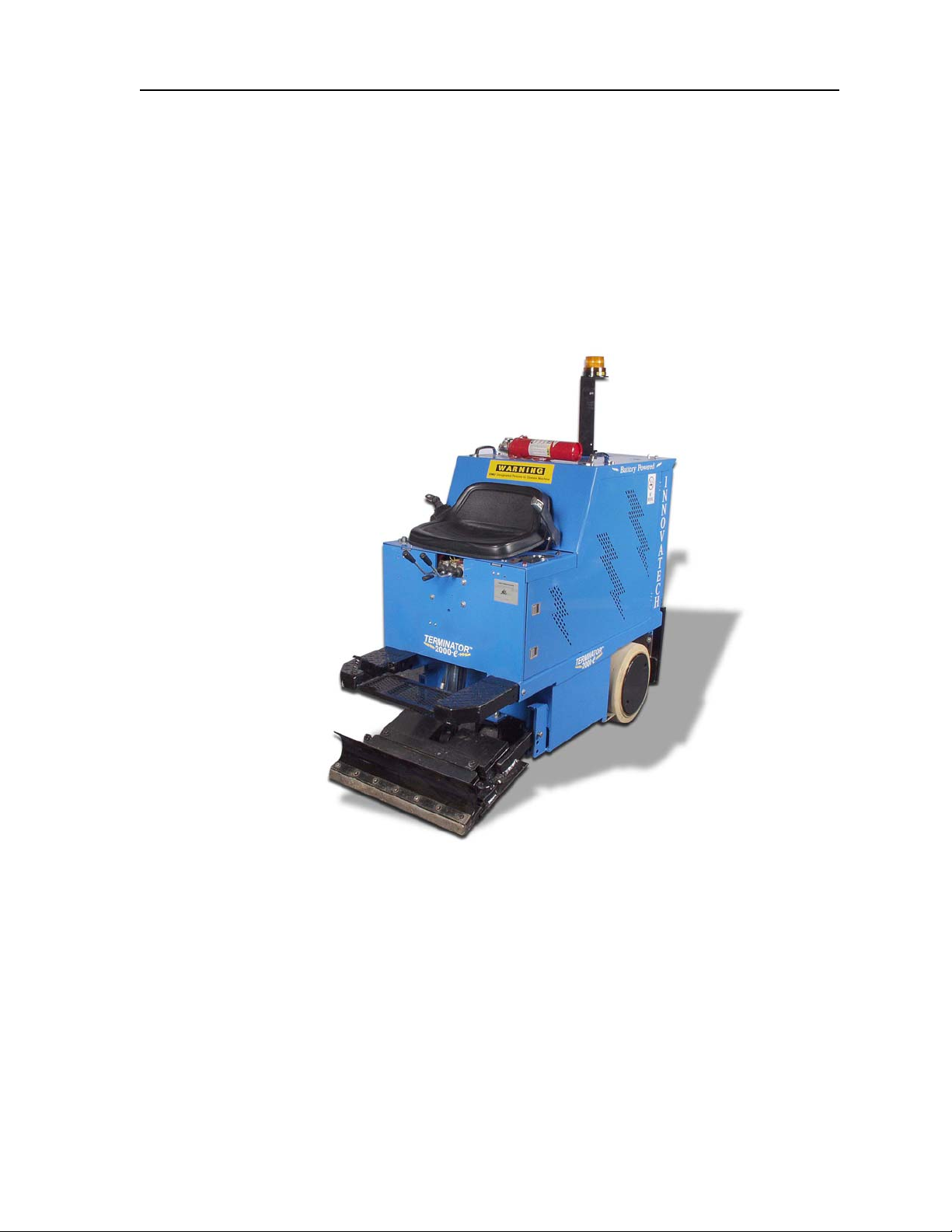
TERMINATOR-2000e ®
THE PROFESSIONAL CARPET AND TILE REMOVAL MACHINE
© Copyright 1994, 2000 Innovatech Products & Equipment Co., Woodinville, Washington USA. All rights reserved.

INNOVATECH PRODUCTS AND EQUIPMENT CO., INC. 3
TABLE OF CONTENTS
INTRODUCTION..........................................................................................................................................................................6
ABOUT THIS MANUAL ................................................................................................................................................6
TERMINATOR® SPECIFICATIONS ..............................................................................................................................7
TOOLS & SUPPLIES ...................................................................................................................................................7
SAFETY INSTRUCTIONS ...........................................................................................................................................................7
GENERAL GUIDELINES FOR SAFE OPERATION .........................................................................................................8
GENERAL OPERATING INSTRUCTIONS FOR THE TERMINATOR ®.............................................................................8
SAFETY FEATURES....................................................................................................................................................8
SAFETY WARNINGS!..................................................................................................................................................9
VENTILATION REQUIREMENTS.................................................................................................................................10
GUARDS, WARNING NOTICES & SIGNS ..................................................................................................................10
SERVICE INSTRUCTIONS & PERSONNEL .................................................................................................................10
REPLACEMENT PARTS & MATERIALS .....................................................................................................................10
UNCRATING THE TERMINATOR ® AND PREPARING IT FOR OPERATION .......................................................................11
LOADING/UNLOADING PROCEDURES:.....................................................................................................................12
COMPONENTS AND OPERATING SYSTEMS ........................................................................................................................ 13
OPERATOR CONTROLS ...........................................................................................................................................14
POWER LIMITER AND KEY SWITCH..........................................................................................................................15
BATTERY DISPLAY, HYDRAULIC OIL LIGHT, CONSOLE LOCK .................................................................................15
BLADE ASSEMBLY.................................................................................................................................................................. 16

INNOVATECH PRODUCTS AND EQUIPMENT CO., INC.
4
INSTALLING A BLADE ...............................................................................................................................................16
ADJUSTING BLADE TILT...........................................................................................................................................16
TAKING UP FLOOR COVERINGS ..............................................................................................................................17
BALLAST .................................................................................................................................................................................. 17
TRICYCLE OR CASTER WHEELBASE AND TIRES ............................................................................................................... 18
HOOD AND OPERATOR SEAT................................................................................................................................................ 19
REMOVING THE HOOD .............................................................................................................................................19
CLOSE OF DAY OR SHIFT ...................................................................................................................................................... 20
TROUBLE-SHOOTING GUIDE ................................................................................................................................................. 21
MAINTENANCE PROCEDURES .............................................................................................................................................. 22
TERMINATOR® MAINTENANCE SCHEDULE ........................................................................................................................ 24
BATTERY SAFETY ................................................................................................................................................................... 25
RECEIVING THE TERMINATOR 2000E......................................................................................................................25
HAZARDOUS ELEMENTS ..........................................................................................................................................25
LIFTING BATTERIES .................................................................................................................................................26
WEARING PROTECTIVE CLOTHING .........................................................................................................................26
SETTING UP A CHARGING AREA .......................................................................................................................................... 26
CONNECTING/DISCONNECTING CHARGER .............................................................................................................27
BASIC CHARGING FACTS.........................................................................................................................................27
THE CHARGING PROCESS.......................................................................................................................................28
TEMPORARY STORAGE OF BATTERY PACK....................................................................................................................... 28
FIRST AID ................................................................................................................................................................................. 29

INNOVATECH PRODUCTS AND EQUIPMENT CO., INC. 5
FIRST AID FOR ACID SPLASHES..............................................................................................................................29
EYE WASH AND EMERGENCY SHOWER FACILITIES.......................................................................................................... 30
BASIC RULES FOR BATTERY CARE AND MAINTENANCE ................................................................................................. 31
WARRANTY .............................................................................................................................................................................. 32
MATERIAL SAFETY DATA SHEET.......................................................................................................................................... 33
TERMINATOR 2000-E PARTS CATALOG .......................................................................................................45
TERMINATOR 2000-E PARTS LIST......................................................................................................................................... 46
T-2000E HYDRAULIC ASSEMBLY .............................................................................................................................46
T-2000E LOWER ASSEMBLY ....................................................................................................................................48
UPPER FRAME ASSEMBLY ........................................................................................................................................50
T-2000E FRONT CONSOLE ASSEMBLY.....................................................................................................................52
T-2000E TOP COVER ASSEMBLY..............................................................................................................................54
T-2000E DOOR ASSEMBLY ......................................................................................................................................56
Table Of Figures
Figure 1 – Batteries and Motor ................................................................................................................ 13
Figure 2 - Operator Controls.................................................................................................................... 14
Figure 3 - Information Displays ............................................................................................................... 15
Figure 4 - Blade Assembly ....................................................................................................................... 16
Figure 5 - Front Weight Ballast................................................................................................................ 17
Figure 6 - Rear Weight Ballast ................................................................................................................. 18
Figure 7 - Front Caster Wheel.................................................................................................................. 18
Figure 9 - Hood & Operator Seat ............................................................................................................. 19

INNOVATECH PRODUCTS AND EQUIPMENT CO., INC.
6
INTRODUCTION
The Terminator® Carpet and Tile Removal Machine is intended for use on large demolition and
asbestos abatement projects as well as smaller floor covering removal jobs. Designed and built by
experienced floor covering demolition and installation experts, the machine incorporates several design
features that are essential for efficient operation:
•
•
•
•
•
Tricycle wheelbase and short turning radius allows for better turning ability – especially in
narrow spaces.
Blade vertical and tilt position adjustments allow for positioning the angle of the blade for each
application.
Ballast in front and rear provides extra traction needed for tile and glue removal.
Built-in forklift transport slots allows for easy loading and unloading at job sites.
Foot control for a very smooth start and stop.
If operated and cared for as instructed in this Manual, the Terminator® provides trouble-free, safe, and
efficient performance.
About This Manual
This Manual contains the information and procedures to assist you to operate and maintain the
Terminator® machine safely and correctly. Read this Manual before you operate or service the
equipment. If you need additional information or assistance, please get in touch with our Customer
Service Department:
Innovatech Products & Equipment Co.
19722 144th Ave. NE
Woodinville, WA 98072 USA
(425) 402-1881 or 800-267-6682
Fax (425) 402-8547
Email: [email protected]
NOTE: Throughout this Manual directional instructions (left, right, up, down, push, pull, etc.) are given
from the point of view of the operator performing the action.

INNOVATECH PRODUCTS AND EQUIPMENT CO., INC. 7
Terminator® Specifications
Element English Metric
Dimensions
Width
Length
Height
Weight (uncrated)
Blades are sold individually
Rear tires are solid rubber,
tubeless, white
26 inches
65 inches
47 inches
2780 pounds
.075 inches thick and
.095 inches thick
.125 inches thick
15" x 8" x 11¼"
.660 m
1.651 m
1.194 m
1251 kg
1.65 mm
2.41 mm
3.18 mm
Electrical Motor 48 volts Not Applicable
Battery 6 volts Not Applicable
Operating speed 0-3600 rpm Not Applicable
Run Time 5 - 6.5 Hours Not Applicable
Tools & Supplies
Maintenance tools and supplies are not provided with the machine. You are responsible for purchase of
these items. The following are suggested items to have on the job site.
1.) 4” or 7” Grinder 6.) WD 40
2.) 10”-15” Crescent Wrench 7.) ¾ Open End and Box Wrench
3.) 16-20 oz. Hammer 8.) Screw Driver Set
4.) 3/8” or ½” Socket Set 9.) Safety Glasses
5.) Grease Gun 10.) Ear Plugs
SAFETY INSTRUCTIONS
The Terminator® is designed for safe operation by trained, designated personnel. To help ensure your
safety as a designated operator, read these safety instructions before you operate the equipment.
Regardless of your experience with machinery, the Terminator® has unique features and systems which
you need to know about and understand before you operate or service the machine.

INNOVATECH PRODUCTS AND EQUIPMENT CO., INC.
8
General Guidelines for Safe Operation
• The Terminator® is to be operated only by qualified, trained personnel.
• Use the Terminator® only for the purpose for which it was designed. Attempting to alter the
Terminator® will invalidate applicable warranties and possibly damage the machine.
• DO NOT use the Terminator® on roofs or floors not designed to carry the weight of the machine. The
Terminator weighs 2,780 lbs.
• Familiarize yourself with all safety features and controls before each use.
• Reduce speed next to walls, machinery and other objects.
• Pre-survey the floor for cracks, ditches, trenches, electrical outlets or bolts, which could catch the
blade of the machine.
General Operating Instructions for the Terminator ®
• The Terminator® is designed to remove carpet, tile and glue residue from floors.
• When removing product, position removed product so it rolls to the side of the machine or have
someone on the side of the machine remove the product. NEVER WALK IN FRONT OF OR BEHIND
THE TERMINATOR® WHILE IT IS RUNNING.
• Sharpen blades or dice material into narrower widths if machine slows down or seems to be struggling.
• Do not use the Terminator® within one foot of walls or stationary objects. Damage to objects may
occur if the Terminator® strikes them.
• Use safe, OSHA approved tools and methods for sharpening blades.
• Make sure the Terminator® has a charged fire extinguisher, working back up beacon and strobe light
before operating.
Safety Features
The Terminator® is equipped with several features to help ensure your safety and the safety of workers
around you.
Warning Light and Back-Up Alarm. An amber light is installed on the top rear section of the hood.
When the Terminator's® ignition is in the ON position, the warning light will flash. When the drive control
is set in REVERSE, the back-up alarm sounds to warn people nearby that the machine is backing up.
Fire Extinguisher. A fire extinguisher with gauge is installed on the hood behind the operator's seat,
within the operator’s reach. As a safety measure, regularly inspect the gauge and recharge the fire
extinguisher as needed to maintain full capacity. Always recharge the extinguisher after each use.
AUTOSTOP. The Terminator® has two drive levers (black) and a blade height lever (black) located
directly below the operator seat. The drive levers control the forward, reverse, left, and right directions of
the machine; the blade height lever raises and lowers the blade. You must push (forward) or pull
(reverse) and hold the levers in position to drive the machine or move the blade in the direction desired.
When you release a lever, the Terminator® or blade automatically STOPS and will not move again until
you push/pull and hold the levers again. However these levers are not meant as brakes. Block wheels
with a floor block when stopping on a ramp. Without the floor block, the machine will roll forward or
backwards on any sloping surface.

INNOVATECH PRODUCTS AND EQUIPMENT CO., INC. 9
Safety Warnings!
FAILURE TO FOLLOW THESE RULES MAY RESULT IN SERIOUS PERSONAL INJURY OR DEATH.
EYE PROTECTION should be worn to provide protection against flying particles both from the front and
side of the Terminator machine. The operator and others should always wear eye protection when
loading, operating, and servicing this machine.
EAR PROTECTION is not required when operating the Electric Terminator® however, ear protection is
recommended if the working area includes exposure to high noise levels, which can lead to hearing
damage.
PROPER VENTILATION shall be in place while charging the battery of the Terminator®.
•
•
•
•
•
•
•
•
•
•
•
•
•
•
•
IF YOU ARE NOT thoroughly familiar with operation of the Terminator®, do not attempt to operate the
machine.
NEVER operate the Terminator® unless every guard, warning notice, or sign is in place.
DO NOT operate the Terminator® while under the influence of drugs, alcohol or medication.
DO NOT operate the Terminator® near and open flame or smoking materials.
DO NOT run the machine onto piles of debris, as this may cause the machine to become unstable and
tip over.
NEVER engage in horseplay.
DO NOT overreach. Keep proper footing and balance at all times. Use the seat belt on the machine.
ALWAYS turn the power OFF when the machine is not in use.
NEVER stand directly behind or in front of the Terminator® when power is enabled.
NEVER put your hands or feet in the blade area when the Terminator® is running.
ALWAYS operate the Terminator® at a safe speed.
NEVER lift the hood, inspect the blade, or otherwise service or maintain the Terminator® while power
is enabled.
DO NOT operate the Terminator® if the top cover is open.
NEVER sit or stand next to, under, or around the Terminator® when it is being transported in a moving
vehicle, whether by itself or with other equipment.
NEVER attempt to use the Terminator® on a non-horizontal surface or turn the Terminator® around on
a ramp or hill.

INNOVATECH PRODUCTS AND EQUIPMENT CO., INC.
10
Ventilation Requirements
• Charge the batteries only in well-ventilated areas.
Guards, Warning Notices & Signs
The guards, warning notices and signs are placed on the Terminator® for your protection. If one of
them becomes damaged or is lost, contact our Customer Service Department to order a replacement.
Service Instructions & Personnel
Like other machinery, the Terminator® requires regular inspection and maintenance of the batteries,
motor, hydraulic system and other parts. To prolong the safe and efficient operating life of the machine,
clean and service it as instructed in the Maintenance section of this manual.
Always use trained personnel to service the equipment. NEVER allow anyone to service the equipment
that has not been specifically trained to do so.
If you need help with a service or maintenance problem, contact our Customer Service Department.
Replacement Parts & Materials
The Terminator® is designed and engineered to operate safely and efficiently with the parts and
materials installed on it in our factory. To ensure the continued safe and efficient operation of the
equipment, use replacement parts and materials that meet both of the following requirements:
o Innovatech must solely authorize replacement parts and materials.
o Replacement parts and materials must be identical to the items originally provided with
the machine, except as authorized by Innovatech.
Never use "equivalent" or substitute parts, except as expressly authorized by Innovatech.
If you fail to adhere to these instructions, you may cause injury to yourself and/or others, cause damage
to the Terminator®, and invalidate applicable warranties.
If you are in doubt about any replacement parts or materials, call our Customer Service Department for
assistance.

INNOVATECH PRODUCTS AND EQUIPMENT CO., INC. 11
UNCRATING THE TERMINATOR ® AND PREPARING IT FOR OPERATION
When you receive the Terminator®, inspect the outside of the crate completely, to detect damage to the
crate itself. If it is damaged, notify the carrier immediately and follow his/her instructions to file a claim.
Carefully uncrate the machine and inspect it for damage that may have occurred during shipping. If the
shipment is damaged, notify the carrier immediately and file a claim in the normal manner.
Check packing slip for complete shipment. If shipment is incomplete, notify our Customer Service
Department within 24 hours.
Remove the crate debris, set aside the blades and other packages, and prepare the Terminator® for
operation:
Raise the hood and prop it open with the hood brace. Be sure the tip of the brace is firmly secure under
the latch. DO NOT MOVE THE TERMINATOR MACHINE WITH THE LID OPEN!
Inspect batteries for spillage during shipment. Check battery water levels before starting the
Terminator.
CAUTION! Wear acid-resistant gloves and safety glasses use extreme care when checking
battery water levels.
DO NOT WORK NEAR A FLAME OR SPARKS.
To remove the TERMINATOR® from crate with a forklift:
1) Remove footrest by pulling the clevis pins out, which are located on the right and left hand sides,
then disconnect the throttle cable. Pull out footrest; this will then expose the forklift slots.
To remove the TERMINATOR® from crate without a forklift:
1) Plug the battery connecters together.
2) Take 2 x 4’s off the edge of the crate and between the wheels.
3) Place 2 x 4’s behind the crate of the rear of the machine.
4) Make a ramp with the 2 x 4’s and the crate material.
5) To enable power to the TERMINATOR®, turn the key, pull up on red knob.
6) Lift front wheel off of the crate 5 inches by pushing down on middle valve. (Jaw will be on crate).
Remove feet from area.
7) Lift up on the left and right handles and depress the foot pedal slowly. The machine will start
moving slowly backwards.
8) Ensure that both rear wheels come off the crate evenly. Failure to back off evenly could result in
the machine tipping over and harm to the operator.
9) As machine rolls back, make sure center wheel clears the crate. If center wheel does not clear
the crate, depress the center handle while pressing the foot pedal until the wheel clears the
crate.
10) Once machine is on the ramp, slide all the way to the bottom, then lift jaw up and set center
wheel down to the ground.
11) Whenever mounting or dismounting the TERMINATOR®, ALWAYS disable the power by
pressing down on the red power knob.

INNOVATECH PRODUCTS AND EQUIPMENT CO., INC.
12
Loading/Unloading Procedures:
• Do not load or unload the Terminator® on uneven ground.
• Ensure ramps into moving vehicles are stable and square to the ground.
• Always turn the Terminator® OFF when you transport the Terminator® by forklift or other vehicle.
• Load and unload the machine with a properly weighted forklift or lift-gate.
• Make sure all safety stops are installed on a lift-gate before loading or unloading.
• Never position yourself under or around the machine while moving it with other machinery.
• Park the machine with the blade completely down after loading.
• Properly secure the machine with chains, tire chocks, and other necessary tie downs.
• Never ride in a moving vehicle next to a Terminator®. It may tip, causing severe injury.
INNOVATECH PRODUCTS AND EQUIPMENT CO., INC. 13
COMPONENTS AND OPERATING SYSTEMS
The major components and the operating systems of the Terminator® are discussed in detail below.
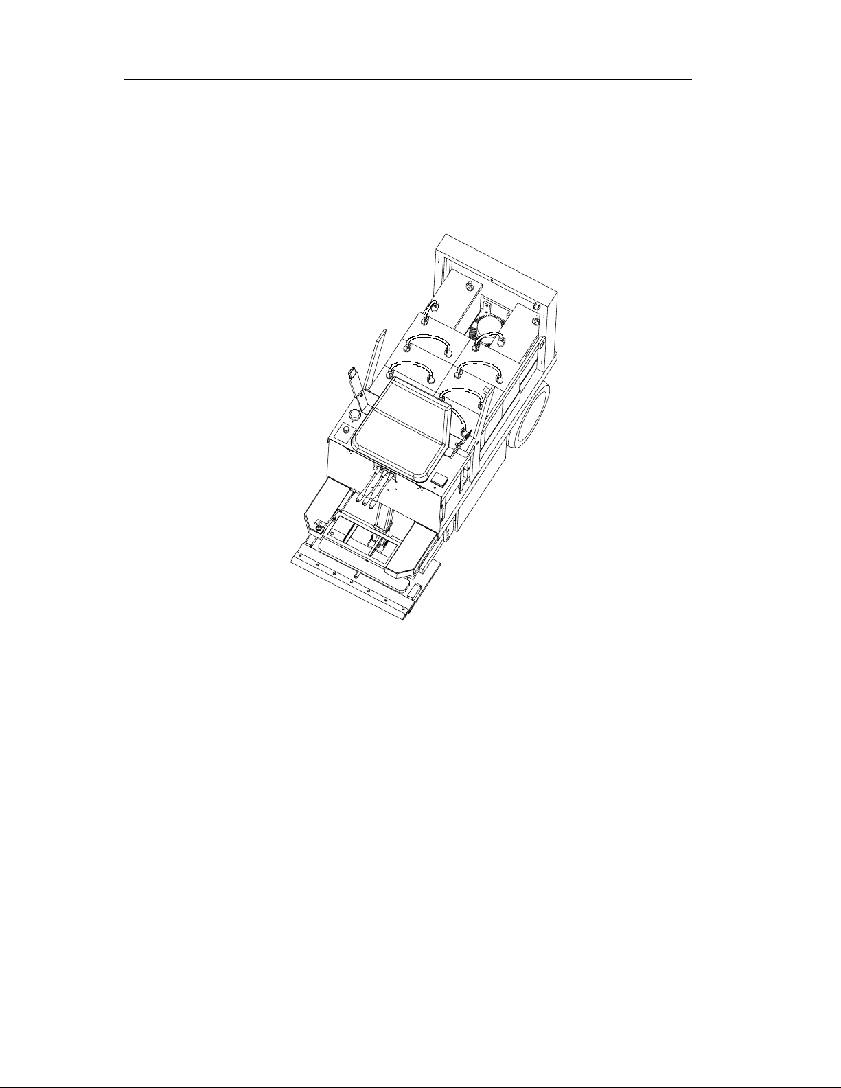
Figure 1 – Batteries and Motor
The electric motor and batteries are located under the hood. The electric motor provides the power
to the hydraulic pump to drive the Terminator®.
The electric motor requires little maintenance, inspect wire connections and check for debris to
maintain its efficiency and prolong its operating life.
INNOVATECH PRODUCTS AND EQUIPMENT CO., INC.
14
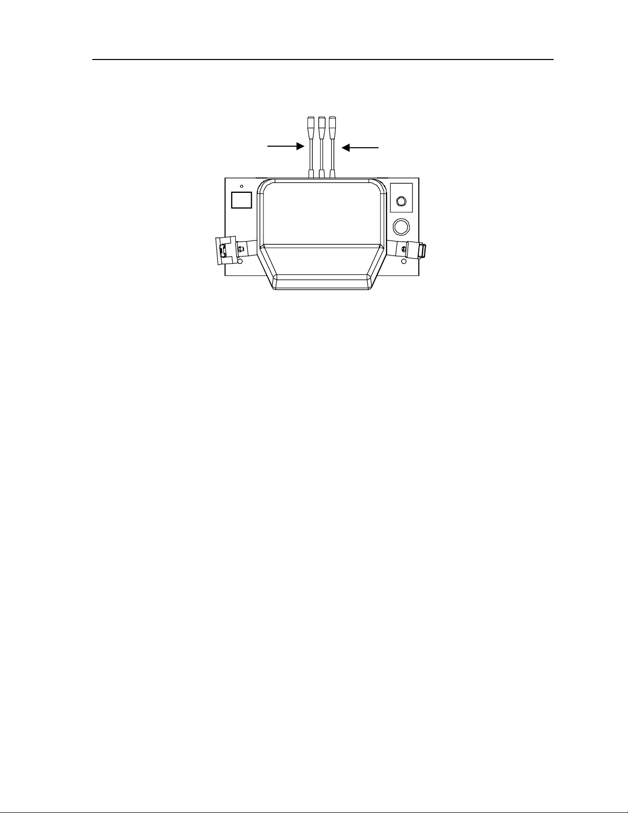
Left Handle:
Push lever down to tur
n
the machine to the right.
Right Handle:
Push lever down to turn
the machine to the left.
Figure 2 - Operator Controls
Operator Controls
The operator controls consist of the drive and blade height levers, a key switch and a foot pedal.
The DRIVE AND BLADE CONTROLS (three levers) are located directly in front of the operator
seat. The drive levers (left and right) control the motion of the rear wheels. The blade height lever
(center) controls the vertical position of the blade. Use these controls as follows with foot pedal
pressed down.
From the view of the seated operator:
Push the left and right levers down together and hold them in position then slowly depress the foot
pedal to move the machine forward.
Pull the left and right levers up together and hold them in position then slowly depress the foot pedal
to move the machine in reverse. (The alarm sounds.)
Push only the left lever down to turn the machine to the right. Push only the right lever down to turn
the machine to the left.
To adjust the blade down, push and hold the center lever down and press the foot pedal to move the
blade down. To adjust the blade up, pull and hold the center lever up and press the foot pedal to
move the blade up.
AUTO STOP: When you release the drive or blade lever, the motor continues to run (with foot control
depressed) but the drive or blade motion automatically stops and will not start again until you push or
pull the levers again.

INNOVATECH PRODUCTS AND EQUIPMENT CO., INC. 15
First Time Driver: Lift Blade Jaw off floor 1-½ inches. Do not install or place the blade into the jaw
until you are familiar with the machine.
PROCEDURES:
1.) Sit on machine and buckle the seat belt. Pull red key knob up to start. With right lever and left
pushed down, slowly press foot control down. The machine will move very little.
2.) As the machine is moving forward if machine drifts left, raise right lever up a little and machine
will straighten out, if the machine drifts to the right lift left lever slightly.
3.) Do not pull lever back abruptly because the machine will turn very sharply. If you lift the levers
up too far, let go of both handles and restart with procedure # 1.
Practice turning left, right, and going forward and backwards until you are comfortable driving the
TERMINATOR®.
4.
1.
2.
5.
3.
Figure 3 - Information Displays
Power Limiter and Key switch
1.) POWER LIMITER is set at 70%, as you increase to 100% it will increase power to the motor.
(Increasing motor power will reduce the run time of the machine)
2.) The KEY SWITCH is located in the right hand side of the gauges/panel. To ENABLE the Motor,
pull the key switch up. In case of emergency push down and all power will be off. ALWAYS push
down this switch to OFF when the Terminator® is not in use.
Battery Display, Hydraulic oil Light, Console lock
3.) BATTERY DISPLAY shows pump use time, key power time and battery life. (When the last box
starts to blink, you have about 15 minutes before battery power is exhausted.)

INNOVATECH PRODUCTS AND EQUIPMENT CO., INC.
16
4.) HYDRAULIC OIL TEMPERATURE Light (a.k.a. hydraulic fluid): Normal temperatures are below
120°F. Do not allow the hydraulic fluid to exceed 200°F because it may damage the hydraulic
system and in turn, damage the Terminator®. If the indicator light is continually coming on, turn
machine off and let it cool for 45-60 minutes. If the light regularly turns on, call Innovatech
Service Department. If you regularly work in a hot climate you may need a hydraulic cooler.
5.) CONSOLE LOCKS need to be locked at all time the machine is in operation and when charging
on job site.
BLADE ASSEMBLY
Blades are available in different configurations and thickness. An assortment of blades is included in
the purchase price of the Terminator®. Extra blades are available upon request from Innovatech
Products & Equipment Co., Inc.
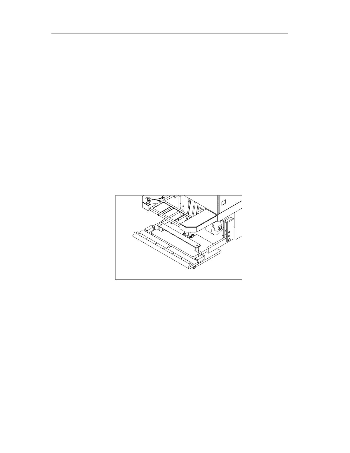
Figure 4 - Blade Assembly
Installing a Blade
1.) Raise the blade assembly to maximum up position, which is five inches off the floor.
2.) Unwrap the pre-sharpened blades and select the blade thickness and length you need for the job.
3.) Loosen the 7 holding bolts.
4.) Insert the sharpened blade.
5.) Tighten bolts firmly, starting from the center and working out. Bolts should be snug but not over
tightened.
Adjusting Blade Tilt
Loosen the blade angle adjustment bolt and manually move the blade to the desired tilt (blade angle is
pre-set to accommodate most conditions); tighten the bolt.
Raise the blade assembly a few inches to clear the floor and prevent damage to the blade while the
Terminator® is in transit.
INNOVATECH PRODUCTS AND EQUIPMENT CO., INC. 17
Taking Up Floor Coverings
1.) Insert blade. (As explained above)
2.) Lower blade to floor. Lift caster wheel off the floor ¼ inch. Use previous procedures to drive
forward.
3.) As the Terminator® is removing flooring material, it is recommended to have another person at the
side of the machine remove all debris.
BALLAST
The Terminator® is equipped with weights in front (75 pounds each) and rear (125 pounds each) to
provide traction for tough jobs. These weights can be removed to reduce traction for certain jobs, and
to transport the Terminator® by forklift or truck or elevator. Wear gloves when handling these weights.
Use caution to not smash toes and fingers. Use OSHA approved lifting technique.
Figure 5 - Front Weight Ballast

INNOVATECH PRODUCTS AND EQUIPMENT CO., INC.
18
Figure 6 - Rear Weight Ballast
TRICYCLE OR CASTER WHEELBASE AND TIRES
The tricycle wheelbase allows better turning ability. The wheel bearings on the front caster roller
require lubrication with grease every 30 hours of machine operation. There are three fittings, two on
the wheel and one on the housing. When running over debris such as carpet, the carpet yarn will get
caught between the wheel and the housing. Clean out wheel and housing regularly.
The rear tires are solid rubber, tubeless, and require no maintenance. Over time, they may wear
out and need to be replaced. Before each job, inspect the rear tires and lug bolts. Tighten the lug bolts
as needed to 70 foot-pounds torque. It is important to keep the lug bolts tight.
Wheel hub should be tightened from 310 to 350 ft.-lbs. Inspect and re-torque every 60 hours of
operation. Lift machine off of floor so no weight is on wheel when re-torquing pack nut.
Figure 8 - Front Caster Wheel Figure 7 - Rear Wheel and Packnut
INNOVATECH PRODUCTS AND EQUIPMENT CO., INC. 19
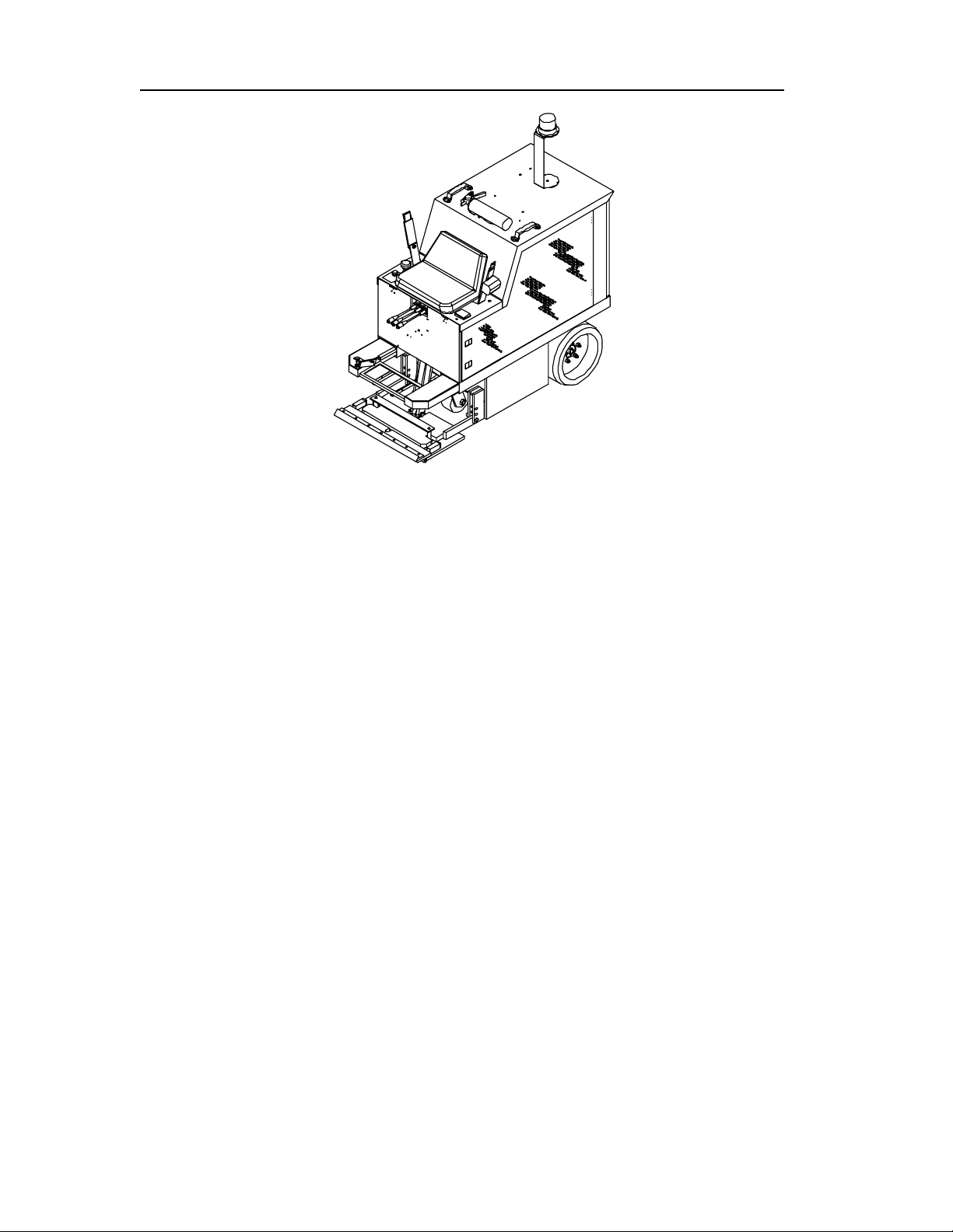
Figure 9 - Hood & Operator Seat
HOOD AND OPERATOR SEAT
The hood covers the batteries, motor and hydraulic system. The top of the hood contains the lift
handles, fire extinguisher, amber back up light, and backup alarm.
Removing the Hood
Remove the 4 bolts and remove the hood.

INNOVATECH PRODUCTS AND EQUIPMENT CO., INC.
20
START OF DAY OR SHIFT
Use the following procedures to start the day or shift or to set up for a new job.
You are ready to test the Terminator® before starting a job or moving it to a job site.
1.) Make sure Batteries are fully charged.
2.) Check all the fuses located under the console panel.
3.) Check for Hydraulic oil leaks.
4.) Check the blade and replace or adjust it as needed for the job.
5.) Check the tires.
6.) Inspect the machine as a whole; to be sure it is ready to run.
7.) Mount machine. Pull keyed knob up for power.
8.) When dismounting machine, push red knob off to kill power.
CLOSE OF DAY OR SHIFT
1.) Hook up battery charger to the loose battery connector, make sure it is charging and lock
console.
2.) Inspect the machine overall to make sure it is okay to run the next day or shift.
3.) For safety, remove key.
Table of contents
Other Innovatech Construction Equipment manuals

Popular Construction Equipment manuals by other brands


McElroy
McElroy TP-300 Series Operator's manual

IMER
IMER Minibeta 1126606 Operating, maintenance, spare parts manual

Aardwolf
Aardwolf Slab Lifter 30AWJ owner's manual

DeWalt
DeWalt D25980-XE instruction manual

Komatsu
Komatsu ecot3 GD655-5 Operation & maintenance manual

Fayat Group
Fayat Group BOMAG BF 700 C S600 Service manual