Innovatech Teerminator-2000 User manual

Read this Manual before you operate or service the equipment.
Carpet and Tile Removal Machinery
Innovatech Products & Equipment Co.
19722 144th Ave NE
Woodinville, WA 98072 USA
Telephone (425) 402-1881
1-800-267-6682
Fax (425) 402-8547
Email: [email protected]
© Copyright 1994, 2000 Innovatech Products & Equipment Co., Woodinville, Washington USA. All rights reserved.

INNOVATECH PRODUCTS & EQUIPMENT CO., INC. 2
TERMINATOR-2000®
THE PROFESSIONAL CARPET AND TILE REMOVAL MACHINE
© Copyright 1994, 2000 Innovatech Products & Equipment Co., Woodinville, Washington USA. All rights reserved.

3 TERMINATOR® OPERATION AND MAINTENANCE MANUAL
INTRODUCTION 5
ABOUT THIS MANUAL .............................................................................................................................6
TERMINATOR® SPECIFICATIONS .............................................................................................................6
TOOLS AND SUPPLIES ..............................................................................................................................6
SAFETY INSTRUCTIONS 7
GENERAL GUIDELINES FOR SAFE OPERATION .........................................................................................7
GENERAL OPERATING INSTRUCTIONS FOR THE TERMINATOR®...............................................................7
SAFETY FEATURES ..................................................................................................................................7
SAFETY WARNINGS!................................................................................................................................8
VENTILATION REQUIREMENTS.................................................................................................................9
GUARDS, WARNING NOTICES AND SIGNS..............................................................................................11
SERVICE INSTRUCTIONS AND PERSONNEL .............................................................................................11
REPLACEMENT PARTS AND MATERIALS ................................................................................................11
UNCRATING THE TERMINATOR® AND PREPARING IT FOR OPERATION 12
LOADING/UNLOADING PROCEDURES:....................................................................................................12
COMPONENTS AND OPERATING SYSTEMS 14
ENGINE AND FAN...................................................................................................................................14
OPERATOR CONTROLS...........................................................................................................................15
IGNITION AND FAN SWITCHES ...............................................................................................................16
SYSTEM GAUGES ...................................................................................................................................16
BLADE ASSEMBLY.................................................................................................................................16
BALLAST ...............................................................................................................................................18
TRICYCLE OR CASTER WHEELBASE AND TIRES .....................................................................................18
HOOD AND OPERATOR SEAT..................................................................................................................19
GEL-CELL BATTERY..............................................................................................................................19
POINTS AND CONDENSOR (H20 ENGINES).............................................................................................20
AIR FILTER ............................................................................................................................................20
HYDRAULIC FLUID CARTRIDGE .............................................................................................................20
FUEL SYSTEM ........................................................................................................................................20
START OF DAY OR SHIFT ...............................................................................................................21
CLOSE OF DAY OR SHIFT ...............................................................................................................21
MAINTENANCE PROCEDURES FOR THE TERMINATOR® 22
TROUBLE-SHOOTING * ..........................................................................................................................22
LIFETIME MAINTENANCE ......................................................................................................................23
LP GAS EQUIPMENT CORPORATION ...........................................................................................24
WARRANTY .......................................................................................................................................24
IMPCO FUEL SYSTEM ADJUSTMENT INSTRUCTIONS.............................................................26
SUPPLEMENTARY INSTRUCTIONS FOR DATSUN FORKLIFTS..............................................28
TERMINATOR® TUNE-UP SPECS/H20 – II (ELECTRONIC IGNITION)......................................31
TROUBLE SHOOTING GUIDE ..................................................................................................................32
BLADE SELECTION GUIDE .....................................................................................................................33
TERMINATOR® MAINTENANCE SCHEDULE ...........................................................................................34
MATERIAL SAFETY DATA SHEET................................................................................................40
PROPANE SAFETY PRECAUTIONS ...........................................................................................................42

INNOVATECH PRODUCTS & EQUIPMENT CO., INC.
4
WARRANTY
44
TERMINA
TOR 2000 PARTS CATAL
OG
45
TERMINATOR 2000 PART
S LIST
46
T-
2000 H
YDRAULIC
A
SSEMBLY ........................................................................................................... 46
T-
2000 E
NGINE
A
SSEMBLY ..................................................................................................................48
T-
2000 F
RONT
C
ONSOLE......................................................................................................................50
T-
2000 W
HEEL
M
OTOR
A
SSEMBLY...................................................................................................... 52
T-
2000 T
OP
C
OVER
A
SSEMBLY............................................................................................................ 54
T-2000 D
OOR
A
SSEMBLY .....................................................................................................................56
TABLE OF FIGURES
F
IGURE
2: E
NGINE AND
F
AN ................................................................................................................. 14
F
IGURE
3:
O
PERATOR
C
ONTROLS ......................................................................................................... 15
F
IGURE 4: C
ONTROL
C
ONSOLE ............................................................................................................. 16
F
IGURE 5: B
LADE
A
SSEMBLY ............................................................................................................... 17
F
IGURE
6: F
RONT
B
ALLAST ..................................................................................................................18
F
IGURE 7: R
EAR
B
ALLAST ....................................................................................................................18
F
IGURE
8: F
RONT
C
ASTER
W
HEEL........................................................................................................ 18
F
IGURE 9: R
EAR
W
HEEL .......................................................................................................................18
F
IGURE 10: H
OOD AND
O
PERATOR
S
EAT ..............................................................................................19
F
IGURE 11: G
EL
-C
ELL
B
ATTERY .......................................................................................................... 19

5 TERMINATOR® OPERATION AND MAINTENANCE MANUAL
INTRODUCTION
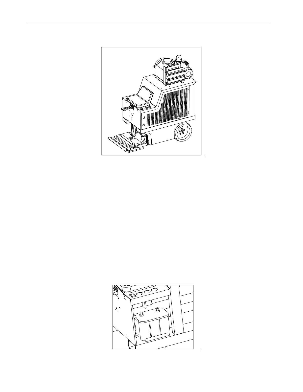
The Terminator® Carpet and Tile Removal Machine is intended for use on large demolition and asbestos
abatement projects as well as smaller floor covering removal jobs. Designed and built by experienced floor
covering demolition and installation experts, the machine incorporates several design features that are essential
for efficient operation:
Tricycle wheelbase and short turning radius allows for better turning ability – especially in narrow spaces.
Blade vertical and tilt position adjustments allow for positioning the angle of the blade for each application.
Ballast in front and rear provides extra traction needed for tile and glue removal.
Gel-cell battery provides durable and reliable performance.
Built-in forklift transport slots allows for easy loading and unloading at job sites.
Propane powered engine provides high fuel efficiency and low air pollution. Propane does however produce
carbon monoxide and other gases, which may be harmful to your health if not used in well-ventilated areas.
See the Ventilation Requirements.
Catalytic Converter provides high fuel economy and lowers emission of harmful gasses.
If operated and cared for as instructed in this Manual, the Terminator® provides trouble-free, safe, and
efficient performance.

INNOVATECH PRODUCTS & EQUIPMENT CO., INC. 6
About This Manual
This Manual contains the information and procedures to assist you to operate and maintain the Terminator®
machine safely and correctly. Read this Manual before you operate or service the equipment. If you need
additional information or assistance, please get in touch with our Customer Service Department:
Innovatech Products & Equipment Co.
19722 144th Ave. NE
Woodinville, WA 98072 USA
(425) 402-1881 or 800-267-6682
Fax (425) 402-8547
Email: sales@the-terminator.com
NOTE: Throughout this Manual directional instructions (left, right, up, down, push, pull, etc.) are given from
the point of view of the operator performing the action.
Terminator® Specifications
Element English Metric
Dimensions
Width
Length
Height
Weight (uncrated)
Blades are sold
individually
Rear tires are solid
rubber, tubeless,
white
26 inches
65 inches
47 inches
2500 pounds
.075 inches thick and
.095 inches thick
combined
15" x 8" x 11¼"
660 mm
1651 mm
1194 mm
1136 kg
1.65 mm
2.41 mm
Engine Nissan H20 4 cylinder,
set at 3500 rpm
Uses 30 weight engine
oil
Not Applicable
Gel-cell battery 12 volts Not Applicable
Operating speed Idle 950-2000 rpm Not Applicable
Propane tank 3 Gallon capacity,
approx.
4 hours operating time
11.3 Liters
Tools and Supplies
Maintenance tools and supplies are not provided with the machine. You are responsible for purchase of these
items. The following are suggested items to have on the job site.
1.) 4” or 7” Grinder 6.) WD 40
2.) 10”-15” Crescent Wrench 7.) ¾ Open End and Box Wrench
3.) 16-20 oz. Hammer 8.) Screw Driver Set
4.) Socket Set ¼ - ¾; 3/8 set or ½ 9.) Safety Glasses
5.) Grease Gun 10.) Ear Plugs

7 TERMINATOR® OPERATION AND MAINTENANCE MANUAL
SAFETY INSTRUCTIONS
The Terminator® is designed for safe operation by trained, designated personnel. To help ensure your safety
as a designated operator, read these safety instructions before you operate the equipment. Regardless of your
experience with machinery, the Terminator® has unique features and systems which you need to know about and
understand before you operate or service the machine.
General Guidelines for Safe Operation
• The Terminator® is to be operated only by qualified, trained personnel.
• Adequate ventilation must be provided when running the Terminator®.
• Use the Terminator® only for the purpose for which it was designed. Attempting to alter the Terminator®
will invalidate applicable warranties and possibly damage the machine.
• DO NOT use the Terminator® on roofs or floors not designed to carry the weight of the machine. The
Terminator weighs 2,500 lbs.
• Familiarize yourself with all safety features and controls before each use.
• Reduce speed next to walls, machinery and other objects.
• Pre-survey the floor for cracks, ditches, or trenches which could catch the blade of the machine.
General Operating Instructions for the Terminator®
• The Terminator® is designed to remove carpet, tile and glue residue from floors.
• Position removed product so it rolls to the side of the machines or is removed by employees standing or
walking at the side of the machine. NEVER WALK IN FRONT OF BEHIND THE TERMINATOR®
WHILE IT IS RUNNING.
• Sharpen blades or dice material into narrower widths if machine slows down or seems to be struggling.
• Do not use the Terminator® within one foot of walls or stationary objects. Damage to objects may occur if
the Terminator strikes them®.
• Use safe, OSHA approved tools and methods for sharpening blades.
• Make sure the Terminator® has a charged fire extinguisher, working back up beacon, and is in a properly
ventilated area before operating.
Safety Features
The Terminator® is equipped with several features to help ensure your safety and the safety of workers around you.
Warning Light and Back Up Alarm. An amber light is installed on the top rear section of the hood. When the
Terminator®'s ignition is in the ON position, the warning light will flash. When the drive control is set in REVERSE,
the BACK UP Alarm sounds to warn people nearby that the machine is backing up.
Fire Extinguisher. A fire extinguisher with gauge is installed on the hood behind the operator's seat, within his/her
reach. As a safety measure, regularly inspect the gauge and recharge the fire extinguisher as needed to maintain full
capacity. Always recharge the extinguisher after each use.
AUTOSTOP. The Terminator® has two drive levers (black) and a blade height lever (black) located directly below
the operator seat. The drive levers control the forward, reverse, left, and right directions of the machine; the blade
height lever raises and lowers the blade. You must push (forward) or pull (reverse) and hold the levers in position
to drive the machine or move the blade in the direction desired. When you release a lever, the Terminator® or blade
automatically STOPS and will not move again until you push/pull and hold the levers again. However these levers
are not meant as breaks. Block wheels with a floor block when stopping on a ramp. Without the floor block the
machine will roll forward or backwards on any sloping surface.

INNOVATECH PRODUCTS & EQUIPMENT CO., INC. 8
Safety Warnings!
FAILURE TO FOLLOW THESE RULES MAY RESULT IN SERIOUS PERSONAL INJURY OR DEATH.
EYE PROTECTION should be worn to provide protection against flying particles both from the front and side
of the machine. The operator and others when loading, operating, and servicing this machine should always wear
eye protection.
EAR PROTECTION should be worn to protect the ears. The working area may include exposure to high noise
levels, which can lead to hearing damage.
PROPER VENTILATION shall be in place while using the Terminator®. Positive or negative pressure
ventilators shall be used in any enclosed space where the Terminator® is operating. Carbon monoxide
monitoring must be used whenever the Terminator® is operated in doors. The Carbon Monoxide (CO) generated
by propane engines in enclosed spaces can be injurious to your health. Use common sense while loading,
operating, and running the machine.
• IF YOU ARE NOT thoroughly familiar with operation of the Terminator®, do not attempt to operate the
machine.
• NEVER operate the Terminator® unless every guard, warning notice, or sign is in place.
• DO NOT operate the Terminator® while under the influence of drugs, alcohol or medication.
• DO NOT operate the Terminator® near and open flame or smoking materials.
• DO NOT run the machine onto piles of debris, as this may cause the machines to become unstable and tip over.
• NEVER engage in horseplay.
• DO NOT overreach. Keep proper footing and balance at all times. Use the seat belt on the machine.
• ALWAYS turn the engine and fuel flow control OFF when the machine is not in use.
• NEVER stand directly behind or in front of the Terminator® when the engine is running.
• NEVER put your hands or feet in the blade area when the engine is running.
• DO NOT exceed recommended speed.
• NEVER refuel, lift the hood, inspect the blade, or otherwise service or maintain the Terminator® while the
engine is running.
• DO NOT move the Terminator® if the engine lid is open.
• NEVER sit or stand next to, under, or around the Terminator® when it is being transported in a moving
vehicle, whether by itself or with other equipment.
• NEVER attempt to use the Terminator® on a non-horizontal surface or turn the Terminator® around on a ramp
or hill.

9 TERMINATOR® OPERATION AND MAINTENANCE MANUAL
Ventilation Requirements
• Use machine only in well-ventilated areas.
• When operating this machine indoors be aware that carbon monoxide will accumulate if proper ventilation is
not provided.
• When in doubt about ventilation stop operation until you are sure the ventilation is adequate.
• A Carbon Monoxide (CO) monitor is highly recommended to monitor the air whenever the Terminator® is
operated indoors.
• Read and understand the following OSHA Fact Sheet regarding carbon monoxide poisoning.
OSHA FACT SHEETS
CARBON MONOXIDE POISONING
U.S. Department of Labor
Program Highlights
Fact Sheet No. OSHA 92-11
WHAT IS IT?
Carbon monoxide -- a colorless, odorless, tasteless gas -- is one of the most common industrial hazards. Mild
poisoning can cause such symptoms as nausea, dizziness or headaches while severe poisoning can result in brain
or heart damage or even death. This poisonous gas is produced by the incomplete burning of any material
containing carbon, such as gasoline, natural gas, oil, propane coal, or wood. Forges, blast furnaces and coke
ovens all produce carbon monoxide, but one of the most common sources of exposure in the workplace is the
internal combustion engine.
Be suspicious of carbon monoxide poisoning if you develop headache, flushed face, dizziness or weakness.
Bear in mind that although carbon monoxide has no telltale odor, it may mix with gases which do have an odor.
Thus, the smell of other gases doesn’t mean the absence of carbon monoxide.
ARE YOU LIKELY TO BE POISONED?
If you have a heart condition, your condition may be aggravated by carbon monoxide. Ingestion of
barbiturates and alcohol may increase the gas’ health effects. Further, smokers will have a higher
carboxyhemoglobin than nonsmokers, and therefore face higher risk from carbon monoxide exposures on the job.
Harmful levels of carbon monoxide are a potential danger to: acetylene workers, blast furnace workers, boiler
room workers, brewery workers, carbon black makers, coke oven workers, customs workers, diesel engine
operators, dock workers, garage mechanics, metal oxide reducers, miners, organic chemical synthesizers,
petroleum refinery workers, pulp and paper workers, steel workers, toll booth and tunnel attendants, and
warehouse workers.
HOW DOES CARBON MONOXIDE HARM YOU?
Large amounts of carbon monoxide can kill in minutes. The more carbon monoxide in the air and the longer
you are exposed to it, the greater the danger. Any one or more of the following symptoms can signal carbon
monoxide poisoning: headaches, tightness across the chest, nausea, drowsiness, inattention or fatigue. As the
amount of carbon monoxide in the air increases, more serious symptoms develop such as lack of coordination,
weakness and confusion.
The poisoning can be reversed if caught in time. But even if you recover, acute poisoning may result in
permanent damage to the parts of your body which require a lot of oxygen, such as the heart and brain. There is a
significant reproductive risk involved with carbon monoxide. An American Journal of Industrial Medicine article
quotes two studies showing that acute carbon monoxide exposures that were non-lethal to the mother were
associated with fetal loss.
WHAT CAN YOU DO ABOUT CARBON MONOXIDE?

INNOVATECH PRODUCTS & EQUIPMENT CO., INC. 10
If you suspect carbon monoxide, get out of the area and into the open fresh air. Remove anyone overcome by
the gas immediately and give the person artificial respiration. Call for a doctor and continue the artificial
respiration until the doctor arrives or the person recovers. Prompt action can make the difference between life and
death.
HOW CAN POISONING BE PREVENTED?
Suggestions for Employers
1.) Install an effective ventilation system to remove poisonous carbon monoxide from the area.
2.) Maintain appliances and equipment in good order, adjusting flames, burners and drafts to reduce the
formation of carbon monoxide.
3.) Consider switching from fossil fuel-powered equipment to battery-powered machinery when possible.
4.) Provide approved respirators for emergency use. Regular respirators (negative pressure) will not work in
this atmosphere. If necessary, provide an independent air supply to workers.
5.) Install carbon monoxide monitors or regularly test air in areas when carbon monoxide is generated or used.
6.) Provide pre-placement and periodic medical examinations for workers who may be exposed to carbon
monoxide. If possible, transfer affected workers to other jobs.
7.) Instruct workers in the hazards of carbon monoxide and train them in the proper use of respirators.
Suggestions for Workers
1.) Report to your employer any condition which might make carbon monoxide form or accumulate.
2.) Be alert to ventilation problems, especially in enclosed areas where gases of burning fuels may be released.
3.) Report complaints early. Don’t overexert yourself if you suspect carbon monoxide poisoning. Physical
activity increases the body’s need for oxygen and thus increases the danger of poisoning.
4.) In you get sick, don’t forget to tell you doctor about the possibility of exposure to carbon monoxide.
5.) Think carefully about your smoking habits. Tobacco, when burned, releases carbon monoxide which
reduces the oxygen-carrying ability of the blood, even before any industrial exposure is added.
WHAT ARE THE FEDERAL STANDARDS?
The Occupational Safety and Health Administration (OSHA) standard for exposure to carbon monoxide
prohibits workers’ exposure to more than 35 parts of the gas per million parts of air (ppm), averaged over an 8-
hour workday. There is also a ceiling limit of 200 ppm (as measured over a 15-minute period.)
* This is one of a series of fact sheets highlighting U.S. Department of Labor programs. It is intended as a general
description only and does not carry the force of legal opinion.

11 TERMINATOR® OPERATION AND MAINTENANCE MANUAL
Guards, Warning Notices and Signs
The guards, warning notices and signs are placed on the Terminator® for your protection. If one of them
becomes damaged or is lost, call our Customer Service Department to order a replacement.
Service Instructions and Personnel
Like other machinery, the Terminator® requires regular inspection and maintenance of the engine, the
operating systems and other parts. To prolong the safe and efficient operating life of the machine, clean and
service it as instructed in the Maintenance section of this Manual.
Always use trained personnel to service the equipment. NEVER allow anyone to service the equipment who has
not been specifically trained to do so.
If you need help with a service or maintenance problem, call our Customer Service Department.
Replacement Parts and Materials
The Terminator® is designed and engineered to operate safely and efficiently with the parts and materials
installed on it in our factory. To ensure the continued safe and efficient operation of the equipment, use
replacement parts and materials that meet both of the following requirements:
Innovatech must authorize replacement parts and materials solely.
Replacement parts and materials must be identical to the items originally provided with the machine, except as
authorized by Innovatech.
Never use "equivalent" or substitute parts, except as expressly authorized by Innovatech.
If you fail to obey these restrictions, you may injure yourself, damage the Terminator®, and invalidate
applicable warranties.
If you are in doubt about any replacement parts or materials, call our Customer Service Department for
assistance.

INNOVATECH PRODUCTS & EQUIPMENT CO., INC. 12
UNCRATING THE TERMINATOR® AND PREPARING IT FOR OPERATION
When you receive the Terminator®, inspect the outside of the crate completely, to detect damage to the crate
itself. If it is damaged, notify the carrier immediately and follow his/her instructions to file a claim.
Carefully uncrate the machine and inspect it for damage that may have occurred during shipping. If the
shipment is damaged, notify the carrier immediately and file a claim in the normal manner.
Remove the crate debris, set aside the blades and other packages, and prepare the Terminator® for operation:
To remove the TERMINATOR® from crate with a forklift:
1.) Remove footrest: pull clevis pin out (located on the right hand side), this exposes forklift slots.
To remove the TERMINATOR® manually:
1.) Put on full propane tank.
2.) Take 2 x 4’s off the edge of the crate and between the wheels.
3.) Place 2 x 4’s behind the crate of the rear of the machine.
4.) Make a ramp with the 2 x 4’s and the crate material.
5.) Start the TERMINATOR® (Do Not sit on the machine).
6.) Lift front wheel off of the crate 5 in. (jaw will be on crate). Remove feet from area.
7.) With right and left lever pull up and move both levers back slowly. The machine will start moving
slowly backwards.
8.) Jaw will roll back on ramp; both wheels have to come off evenly. If no machine will roll to one side. It
is extremely important to back up straight
9.) As machine rolls back, make sure center wheel clears the crate. If not lift wheel higher (center lever).
10.)Once machine is on the ramp slide all the way to the bottom then lift jaw up and set center wheel down
to the ground.
* Whenever mounting or dismounting the TERMINATOR®, ALWAYS turn OFF the engine.
Loading/Unloading Procedures:
• Do not load or unload the Terminator® on uneven ground, make sure ramps into moving equipment are square
to the ground.
• Always turn the engine OFF when you transport the Terminator® by forklift or other vehicle.
• Load and unload the machine with a properly weighted forklift or lift-gate.
• Make sure all safety stops are installed on a lift-gate before loading or unloading.
• Never position yourself under or around the machine while moving it with other machinery.
• Park the machine with the blade completely down after loading.
• Properly secure the machine with chains, tire chocks, and other necessary tie downs.
• Never ride in a moving vehicle next to a Terminator®. It may tip, causing severe injury.
Using a clean cloth, wipe the shipping dust off the machine, paying particular attention to the operator seat
and the gauges on the control panel. Install the fire extinguisher in the clamp behind the operator seat, if they
are removed.
Inspect the lug nuts on the rear wheels; tighten the nuts to 70 inch-pounds torque.
Raise the hood and prop it open with the hood brace. Be sure the tip of the brace is firmly secure under the
latch. DO NOT MOVE MACHINE WITH THE LID OPEN!

13 TERMINATOR® OPERATION AND MAINTENANCE MANUAL
Using the respective dipstick, test the oil level of the engine oil and the hydraulic oil (fluid). Add oil and
hydraulic fluid, if needed.
Inspect the fuel system connectors and the valve; make sure the valve is OFF.
Have two tanks of propane on hand: one to install and one in reserve. (Each tank provides approximately 3 to
4 hours operating time.)
CAUTION! Wear insulated gloves and handle the propane tanks and fuel with extreme
care, according to the manufacturer’s instruction.
DO NOT WORK WITH PROPANE NEAR A FLAME OR SPARKING EQUIPMENT.
Drive or transport the Terminator® to the work site: (first time drivers see page 17)
For Model 2 machines –
If you drive to the site, check the ignition switch and all fuel flow connections to make sure they are OFF.
At the jobsite, install a tank of propane, check the fuel system connectors again, turn the flow switch ON,
remove the hood brace from the locking bracket, lower the brace to its down position, lower the hood and
lock it in place.
Start the engine and let it idle for a few minutes. Raise the blade jaw a few inches to clear the floor and avoid
damage to the blade in transit.
If you transport the Terminator® by forklift or truck, anchor the machine in place with chains, wheel locks,
or other tie down devices.
INNOVATECH PRODUCTS & EQUIPMENT CO., INC. 14
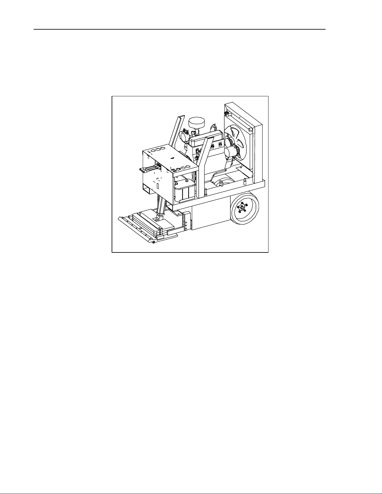
COMPONENTS AND OPERATING SYSTEMS
The major components and the operating systems of the Terminator® are discussed in detail below.
Engine and Fan
Figure 2: Engine and Fan
The propane-powered engine and fan are located under the hood. The engine provides the power to drive
the Terminator®.
The fan ventilates and cools the entire engine and fuel tank area on the older models. A safety guard covers
the fan. NEVER operate the machine unless the guard is in place. If you remove the guard to clean the
fan, replace the guard before you start the engine again. ALWAYS keep your hands away from the fan
when the engine is running.
The engine requires regular inspection and service, to maintain its efficiency and prolong its operating life.
Check the oil level and clarity daily. Change the oil every 60 hours of running. Do not allow the oil to get
muddy before changing it because dirty oil can damage the engine and its parts (see the Maintenance
section for details). If operating machine in very dusty areas, change oil every 40 hours.
Air filter should be checked every day if machine is run 4 or more hours, to make sure it is clean. Blow
dust out or replace with another filter.
15 TERMINATOR® OPERATION AND MAINTENANCE MANUAL
Operator Controls
Left Handle:
Push lever down to turn
the machine to the right.
Right Handle:
Push lever down to turn
the machine to the left.
Figure 3: Operator Controls
The operator controls consist of the drive and blade height levers, ignition and fan switches.
The DRIVE AND BLADE CONTROLS (three levers) are located directly in front of the operator seat. The
drive levers (left and right) control the motion of the rear wheels. The blade height lever (center) controls the
vertical position of the blade. Use these controls as follows:
From the view of the seated operator:
Push the left and right levers forward together and hold them in position = the machine moves forward.
Pull the left and right levers together toward you and hold them in position = the machine moves in reverse.
(The alarm sounds.)
Push the left lever only = the left rear wheel turns the machine to the right
Push the right lever only = the right rear wheel turns the machine to the left.
Push and hold the blade height lever (center) forward to lower the blade; pull and hold the lever toward you to
raise the blade.
AUTO STOP: When you release a drive or blade lever, the engine continues to run but the drive or blade
motion automatically stops and does not start again until you push or pull and hold the lever again.
First Time Driver: Lift Blade Jaw off floor 1 ½ inches. Do not put the blade into the jaw until familiar with
the machine.
1.) Sit on machine and buckle the seat belt. Start engine. With right lever slowly push down, engine’s
rpm’s will lower and the machine will move very little. Hold the levers there.
2.) Left lever move slowly and machine will move forward, at that moment push both, left and right levers
all the way down.
3.) As the machine is moving forward if machine drifts left, raise right lever up a little and machine
will straighten out, if the machine drifts to the right lift left lever slightly.
4.) Do not pull lever all the way back abruptly because the machine will turn very sharply. If you lift
levers to far, let go of both handles and restart with procedure # 1.
Practice turning left, right, and going forward and backwards until you are comfortable driving the TERMINATOR®.

INNOVATECH PRODUCTS & EQUIPMENT CO., INC. 16
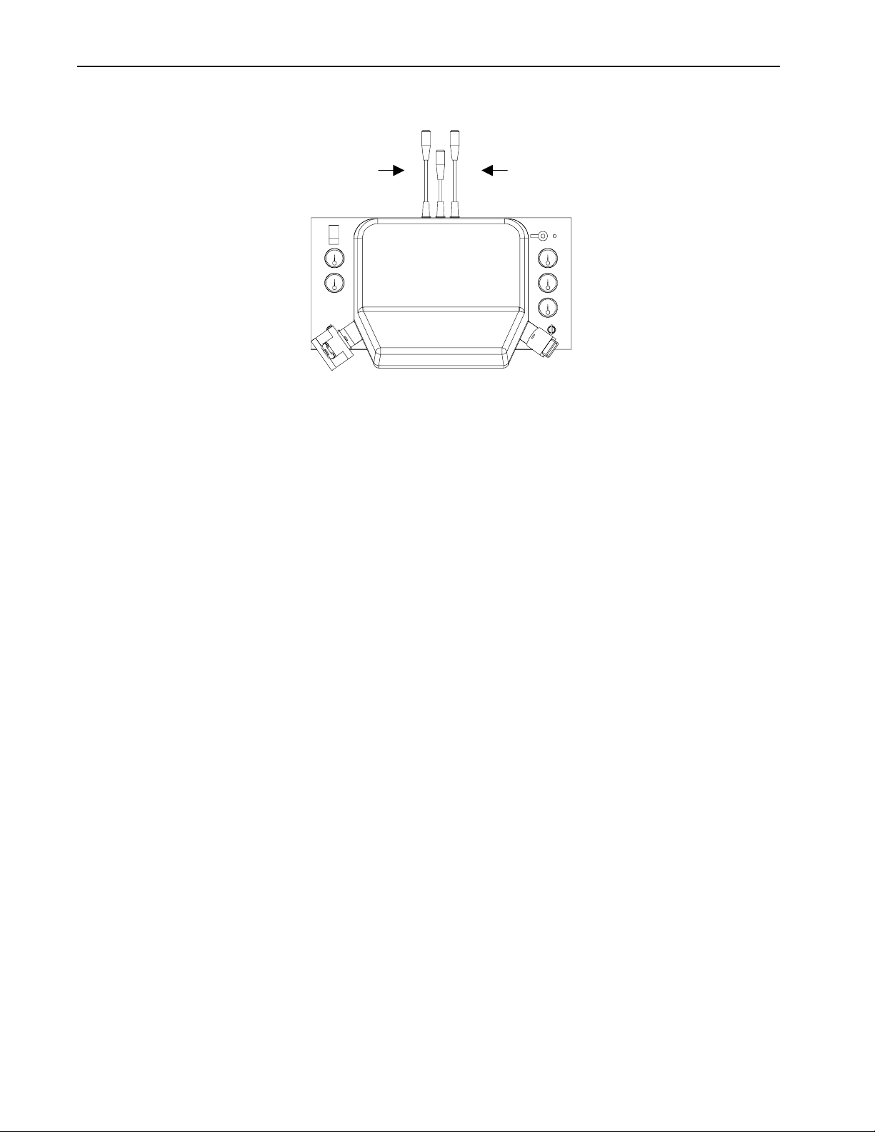
Ignition and Fan Switches
1.
3.
4.
2.
7.
6.
5.
Figure 4: Control Console
1.) The IGNITION SWITCH (selector ON/OFF/START) is located in the upper right hand corner of the
gauges panel. To START the engine, turn the key switch ON (key switch is on some models). Pause for
one or two seconds, turn to START and hold until the engine fires, then release the switch. ALWAYS
turn this switch OFF when the Terminator® is not in use.
2.) The HEADLIGHT SWITCH (ON/OFF toggle) is located on the system gauges panel. Do not leave the
fan switch ON when the machine is not in use.
System Gauges
The system gauges monitor the Terminator®’s various operating systems. These gauges are located on the
system gauges panel and consist of the following:
3.) AMP/ALTERNATOR: shows battery activity.
4.) HOUR METER: shows the exact running time of the machine. The hour meter will continue to run
while the key and lever ignition switch are on.
5.) HYDRAULIC OIL TEMPERATURE (a.k.a. hydraulic fluid): Normal temperatures are below 120°F.
Hydraulic fluid temperature exceeding 200°F may damage the hydraulic system and in turn, damage the
Terminator®.
6.) OIL PRESSURE GAUGE: shows the oil pressure of the engine lubricant. During normal operation, this
gauge should register in the safe range shown on the dial (40-60 PSI). If this pressure drops suddenly,
shut the engine OFF immediately and check the oil supply. NEVER attempt to operate the Terminator®
without adequate oil because you will destroy the engine and its parts. If water or oil temperatures exceed
maximum temperature, lift lid and remove side panels. Let run for five minutes. Turn machine off to
cool for 30-60 minutes. If possible, let cool by an open outside door or window. Never remove radiator
cap if water is boiling out. Always, let the machine cool down.
7.) WATER TEMPERATURE GAUGE: normal range is 190°F-230°F. When the machine is new, this
gauge may register 220°F-250°F for the first 50± hours of operation. This is the normal break-in period.
After this break-in period, the gauge shows the actual temperature of the water.
Blade Assembly
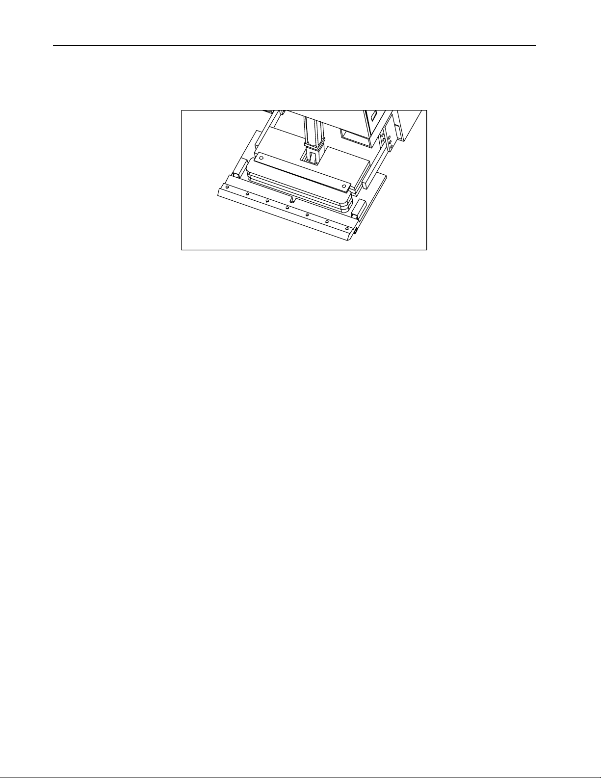
17 TERMINATOR® OPERATION AND MAINTENANCE MANUAL
Blades are available in different configurations and thickness. An assortment of blades is included in the
purchase price of the Terminator®. Extra blades are available upon request from Innovatech Products &
Equipment Co., Inc.
Figure 5: Blade Assembly
Installing a Blade
1.) Lower the blade assembly to maximum down position, which is two inches off the floor.
2.) Unwrap the pre-sharpened blades and select the blade thickness and length you need for the job.
3.) Loosen the 7 holding bolts.
4.) Insert the sharpened blade.
5.) Tighten bolts firmly, starting from the center and working out. Bolts should be snug but not over
tightened.
Adjusting Blade Tilt
Loosen the blade angle adjusting bolt and manually move the blade to the desired tilt (angle is set at factor for
80% of the job); tighten the bolt. Raise the blade assembly a few inches to clear the floor and prevent damage to
the blade while the Terminator® is in transit.
Taking Up Floor Coverings
1.) Insert blade. (As shown above)
2.) Lower blade to floor. As the blade flexes lift caster wheel off the floor ¼ inch. Use previous procedures to
drive forward.
3.) As the Terminator® is removing flooring material have another person at the side of the machine remove
all debris.
INNOVATECH PRODUCTS & EQUIPMENT CO., INC. 18
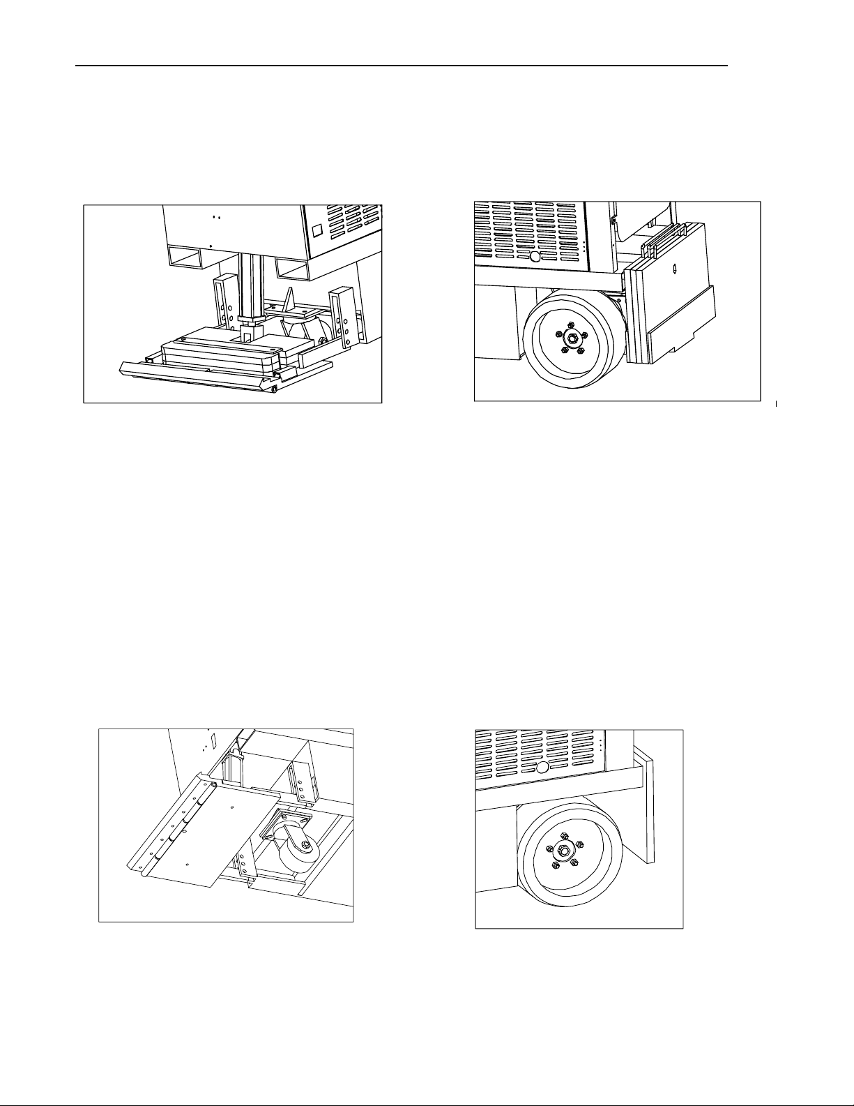
Ballast
The Terminator® is equipped with weights in front (75 pounds each) and rear (125 pounds each) to provide
traction for tough jobs. These weights can be removed to reduce traction for certain jobs, and to transport the
Terminator® by forklift or truck or elevator. Wear gloves when handling these weights. Use caution to not
smash toes and fingers. Use weight procedures from OSHA.
Figure 6: Front Ballast
Figure 7: Rear Ballast
Tricycle or Caster Wheelbase and Tires
The tricycle wheelbase allows better turning ability. The wheel bearings on the front caster roller require
lubrication with grease every 30 hours of machine operation. There are three fittings, two on the wheel and
one on the housing. When running over debris such as carpet, the carpet yarn will get caught between the
wheel and the housing. Clean out wheel and housing regularly.
The rear tires are solid rubber, tubeless, and require no maintenance. Over time, they may wear out and
need to be replaced (see the Maintenance section for replacement procedure). Before each job, inspect the rear
tires and lug bolts. Tighten the lug bolts as needed to 70 foot-pounds torque. It is important to keep the lug
bolts tight.
Wheel hub should be torqued from 250 to 300 foot pounds (ft.lbs.). Inspect and re-torque every 60 hours of
operation. Lift machine off of floor so no weight is on wheel when re-torquing pack nut.
Figure 8: Front Caster Wheel
Figure 9: Rear Wheel
19 TERMINATOR® OPERATION AND MAINTENANCE MANUAL
Hood and Operator Seat
Figure 10: Hood and Operator Seat
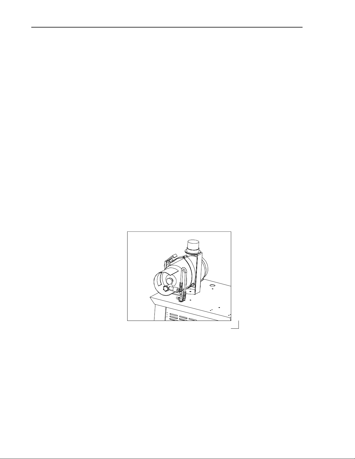
The hood covers the engine, fan, fuel supply and their related system. The top of the hood contains the
operator seat, fire extinguisher, amber back up light, and the propane tank. The water mister and inverter package
are optional accessories. On older models of the Terminator® the hood and seat are removable to aid in
transporting the machine in a truck or building elevator.
Removing the Hood
Remove the 4 bolts and remove the hood.
Removing the Operator Seat
After you remove the hood, turn the hood on its side and remove the holding nuts and bolts of the seat.
Remove the seat. Screw the nuts and bolts back on the seat, to prevent loosing them in transit.
Gel-Cell Battery
The GEL-CELL BATTERY is self-contained and does not require maintenance. In normal operating
situations, it has an operating life of about three years. NEVER attempt to use any other type of battery in the
Terminator® because you will injure yourself, damage the equipment, and invalidate applicable warranties. When
the battery needs to be replaced, call Innovatech Service Department for assistance.
Figure 11: Gel-Cell Battery
INNOVATECH PRODUCTS & EQUIPMENT CO., INC. 20
Points and Condensor (H20 Engines)
On older models of the Terminator® the points and condenser are part of the ignition system and need to be
replaced annually or every 200 hours running time.
Air Filter
The air filter helps prevent dust and dirt from entering the engine. Inspect the air filter before operating each
day and replace when dirty.
Hydraulic Fluid Cartridge
Inspect the hydraulic fluid cartridge regularly and replace the filter when it gets dirty. It is recommended that
the hydraulic fluid and filter be changed annually and if fluid is overheated 160°F – 180°F or higher. On 2000
models hydraulic filter should be changed every 60 hours when engine oil is changed. For every filter change you
loose approximately 1 pint of oil. So on the 8th filter change, you should add one gallon of oil.
Fuel System
STOP!
Read the propane material safety data sheets
and safety rules on pages 42-45 before proceeding.
The fuel system consists of propane tank, fuel lines, connectors, and flow control. The Terminator® is
designed to accommodate a three gallon tank, which will usually provide about three to four hours running
time. Keep a reserve tank on hand.
LPG FUEL CYLINDER REPLACEMENT PROCEDURE
1.) NO SMOKING – Do not replace fuel cylinders in areas that have a source of fuel ignition.
2.) Close cylinder valve and run engine until it stops prior to disconnecting the fuel hose from the tank.
3.) Connect fuel hose. Open valve slowly so the hose and tank pressure can equalize or the valve may slug. Should leakage occur,
close valve and have qualified personnel make repairs.
4.) Use fuel manufactured National Gas Processors association “HD-5” specification.
NOTE: THE ABOVE IS PROVIDED AS A GUIDE. FOR ADDITIONAL INFORMATION, CONSULT THE NATIONAL FIRE
PROTECTION ASSOCIATION PAMPHLET 58 FOR THE SAFE STORAGE AND HANDLING OF LIQUEFIED PETROLEUM
GASES.
NOLFF’S Carburetion, Inc. 1-800-451-7040
Table of contents
Other Innovatech Construction Equipment manuals


