Innovative Water Care Pulsar Acid Plus System Specification sheet

Rev. 1.0
06/2022
Operaon and Installaon Manual
Pulsar® Acid Plus System
Model PS-1AP

Pulsar® Acid Plus System Operaon and Installaon Manual (Model PS-1AP) Rev 1.0 06/2022
2
Table of Contents
1 SafetyPrecauons ........................................................................4
1.1 SafetyConvenons.....................................................................4
1.2 Safety Statements for the Pulsar Acid Plus..................................................5
2 Introducon..............................................................................6
2.1 OverviewofOperaon..................................................................6
2.2 Process Flow Diagram ..................................................................7
3 Pulsar®AcidPlusFeederOverview ...........................................................8
3.1 Components List.......................................................................8
4 Pre-installaonInstrucons .................................................................9
4.1 Prepare the Site .......................................................................9
4.1.1 Site Requirements..............................................................9
4.2 GatherEquipmentforFeederInstallaon ..................................................9
4.2.1 Pulsar® Acid Plus Components ...................................................9
4.2.2 EssenalEquipmentSuppliedbyOthers ..........................................10
4.2.3 COTS Tools . . . . . . . . . . . . . . . . . . . . . . . . . . . . . . . . . . . . . . . . . . . . . . . . . . . . . . . . . . . . . . . . . . .10
4.2.4 PPE .........................................................................10
4.3 Pre-InstallaonChecklist ...............................................................10
5 InstallaonInstrucons ...................................................................11
5.1 Install Booster Pump- Venturi Loop ......................................................11
5.2 FeederSetup–DischargeValve(DV)AssemblytoVenturiSucon.............................12
5.3 Feeder Setup – Feeder inlet line from booster pump discharge ...............................13
5.4 Feeder Setup if pairing with a Pulsar® Precision Chlorine Feeder ..............................13
5.5 Wire the Booster Pump to facility power (Generic Chlorine Feeder Use)........................14
5.6 Prime the System .....................................................................14
6 Post-InstallaonInstrucons ...............................................................15
6.1 Post-InstallaonChecklist ..............................................................15
6.2 System Startup .......................................................................16
6.2.1 System Power Up .............................................................16
6.2.2 FeederPreparaon ............................................................16
7 OperaonInstrucons ....................................................................17
8 PreventaveMaintenance .................................................................18
8.1 PreventaveMaintenanceSchedule .....................................................18
8.3 Cleaning Procedures ..................................................................20
8.3.1 Equipment Needed ............................................................20
8.3.2 CleaningInstrucons ..........................................................20
9 TroubleshoongGuide ....................................................................21
10 Appendix ...............................................................................22
10.1 RequirementsandSpecicaons ........................................................22
10.1.1 RequirementsforProductInstallaonandOperaon................................22
10.1.2 ProductSpecicaons .........................................................22
10.1.3 Product Footprint .............................................................23
10.2 Replacement Parts List and Views .......................................................24
LimitedWarranty .............................................................................28

Pulsar® Acid Plus System Operaon and Installaon Manual (Model PS-1AP) Rev 1.0 06/2022 3
List of Figures
Figure1. Pulsar®AcidPlusfeederwithPulsar®Precisionfeederinstallaon .............................7
Figure2. Pulsar®AcidPlusSystemOverview .......................................................8
Figure3. 1½”boosterpumpandventuriassembly .................................................11
Figure4. Feederconneconstoboosterpumpandventuri ..........................................12
Figure5. Dual-voltageselector..................................................................14
Figure6. ProductFootprint ....................................................................23
Figure7. MajorFeederComponentsView ........................................................24
Figure8. BaseInletComponents ................................................................25
Figure9. BaseOutletComponents ..............................................................26
Figure10. BoosterPumpandVenturiAssembly....................................................27
List of Tables
Table1. Pre-installaonChecklist ...............................................................10
Table2. Post-InstallaonChecklist ..............................................................15
Table3. MonthlyMaintenance .................................................................18
Table4. SemiannualMaintenance...............................................................19
Table5. TroubleshoongGuide .................................................................21
Table6. SiteRequirements.....................................................................22
Table7. AccessoryRequirements................................................................22
Table8. OperaonalSpecicaons ..............................................................22
Table9. ChemicalFeedRateSpecicaons........................................................23

Pulsar® Acid Plus System Operaon and Installaon Manual (Model PS-1AP) Rev 1.0 06/2022
4
1 SafetyPrecauons
Danger, Warning, Cauon, and Note statements are used throughout this manual to emphasize important safety informaon. The
statements are dened below.
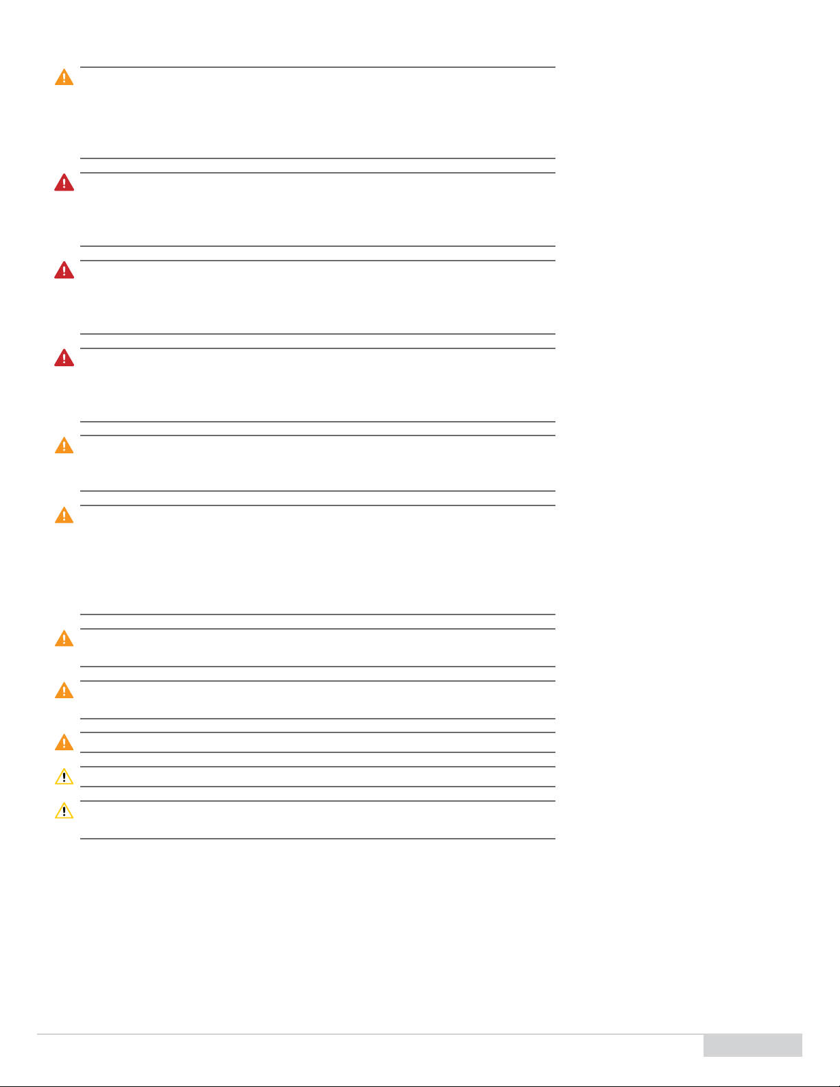
1.1 SafetyConvenons
Danger: Indicates a hazardous situaon which, if not avoided, will result in death or severe
injury.
Warning: Indicates a potenally hazardous situaon which, if not avoided, can result in
personal injury.
Cauon: Indicates a potenally hazardous situaon which, if not avoided, can result in minor
personal injury or equipment damage.
Note: Informaon that may assist in compleng a task correctly or for maintaining the
machine in good operang condion.
Pulsar® Acid Plus System Operaon and Installaon Manual (Model PS-1AP) Rev 1.0 06/2022 5
1.2 Safety Statements for the Pulsar Acid Plus
Warning: For your protecon, carefully and completely read the informaon provided in this
manual before aempng to assemble, install, operate, or maintain this product.
Retain these instrucons for future reference. Failure to follow the instrucons or
informaon in this manual may result in injury and damage to the product and may
aect warranty coverage.
Danger: Sodium bisulfate causes severe skin burns and eye damage. Please see the Safety
Data Sheet for addional informaon and precauons regarding the proper
handling of Pulsar® pH Down (+4) dry acid. If any part of this prole is unclear to
you, please stop immediately and contact Innovave Water Care at (800) 478-5727.
Danger: This system contains liquid under pressure and sodium bisulfate soluon can be
discharged unexpectedly. Operate and service all components and aached piping
that contains liquid cauously unl you are certain that the system has been
depressurized and drained. Failure to do so may result in serious injury.
Danger: Use suitable personal protecve equipment (PPE) at all mes to avoid physical
contact with sodium bisulfate liquid or vapor. Failure to do so may result in serious
injury. See the Safety Data Sheet for addional informaon and precauons
regarding the proper handling of Pulsar® pH Down (+4).
Warning: Clean up, without delay, any leakage or spillage of Pulsar® pH Down (+4). See the
Safety Data Sheet for addional informaon and precauons regarding the proper
disposal of Pulsar® pH Down (+4). Failure to do so may result in serious injury.
Warning: All wiring connecons, fusing, grounding, inspecon, and maintenance of wiring
must be performed by a licensed electrician in accordance with the Naonal
Electric Code (NEC), Occupaonal Safety and Health Act (OSHA) in the United
States, and all local electrical codes. Failure to properly install and wire this product
can result in property damage, serious injury, or death, and may aect warranty
coverage.
Warning: Always operate system with electrical component enclosures in place. Failure to do
so may result in injury.
Warning: Always operate system components with safety guards in place. Failure to do so
may result in injury.
Warning: Observe and follow all plant safety procedures. Failure to do so may result in injury.
Cauon: Do not paint over or remove unit nameplates, labels, or tags.
Cauon: Use of any dry acid or chemicals other than the Pulsar® pH Down (+4) designed for
use with this feeder shall void this warranty and NSF cercaon.

Pulsar® Acid Plus System Operaon and Installaon Manual (Model PS-1AP) Rev 1.0 06/2022
6
2 Introducon
The Pulsar® Acid Plus feeder creates a consistent soluon of sodium bisulfate acid used for pH reducon.
2.1 OverviewofOperaon
The feeder operates as follows:
1. Pulsar® pH Down (+4) is loaded into the hopper suspended over the soluon reservoir.
2. The external solenoid valve power supply is plugged into a chemical controller pH dosing output.
3. When the chemical controller calls for a pH correcon, the feed solenoid valve opens allowing Water from the pool return to enter the
inlet water manifold at the proper supply ow rate.
4. Water sprays the boom of the basket through three 90° full cone nozzles.
5. Pulsar® pH Down (+4) dry acid dissolves and creates a 93% sodium bisulfate soluon. 10 lbs of sodium bisulfate is equivalent to 1 gallon of
muriac acid..
6. The sodium bisulfate soluon lls the reservoir liing the oat connected to the discharge valve unl the valve opens.
7. With the discharge valve and outlet tubing connected to a venturi, the vacuum generated by the venturi sucon drains the reservoir tank
of the acid soluon, sending the soluon back into the pool return.
Note: If using the same booster pump and Venturi as the precision feeder as shown in
the schemac, set booster pump to Always On by seng dip switch 4 to OFF in the
control box.
Note: If not using a Pulsar® Precision feeder as the primary sanizer, a dedicated booster
pump and venturi is required for operaon of the Pulsar® Acid Plus feeder.
Note: If not using the Pulsar® Precision feeder control box for booster pump operaon,
other means of interlocking the booster pump to the pool pump is required to
protect the booster pump and prevent accidental dosing in a no ow condion.
Pulsar® Acid Plus System Operaon and Installaon Manual (Model PS-1AP) Rev 1.0 06/2022 7
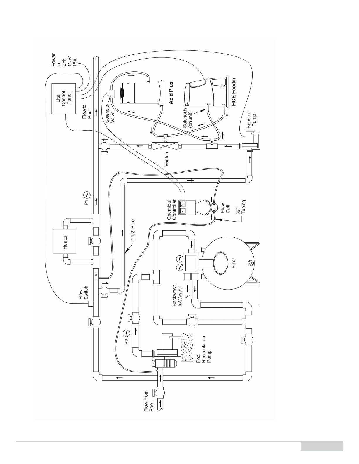
2.2 Process Flow Diagram
Figure1. Pulsar® Acid Plus feeder with Pulsar® Precision feeder installaon

Pulsar® Acid Plus System Operaon and Installaon Manual (Model PS-1AP) Rev 1.0 06/2022
8
3 Pulsar®Acid Plus Feeder Overview
Figure2. Pulsar® Acid Plus System Overview
3.1 Components List
The Pulsar® Acid Plus product includes these components:
A. Hopper, includes:
A1 Chemical tank
A2 Meshed grid
B. Base, includes:
B1 Spray manifold
B2 Emergency shuto valve assembly
B3 Discharge valve assembly
B4 Soluon mixing manifold
C. ORP kit with solenoid valve and power supply
D. Booster pump and Venturi, installaon kit
A
B
C
D

Pulsar® Acid Plus System Operaon and Installaon Manual (Model PS-1AP) Rev 1.0 06/2022 9
4 Pre-installaonInstrucons
4.1 Prepare the Site
Before installing equipment, ensure that:
1. The site has all electrical connecons installed. All electrical lines should be secured to meet site safety procedures and to prevent tripping
over electrical lines.
Danger: All wiring connecons, fusing, grounding, inspecon, and maintenance of wiring
must be performed by a licensed electrician in accordance with the Naonal
Electric Code (NEC), Occupaonal Safety and Health Act (OSHA) in the United
States, and all local electrical codes. Failure to properly install and wire this product
can result in property damage, injury, or death, and may aect warranty coverage.
2. Site meets criteria noted in 4.1.1 Site Requirements.
4.1.1 Site Requirements
The feeder must t in the selected room with enough clearance for maneuvering and servicing the equipment.
Recommended clearance for feeder installaon is 48" L x 48" W x 76" H [121.9 cm x 121.9 cm x 152.4 cm]
Minimum clearance for feeder installaon is 29 L x26.5" W x45.9" H [73.6 cm x 67.3 cm x 116.6 cm].
The room must have proper venlaon.
The room must be climate-controlled between 40°F – 90°F [4°C – 32°C].
Required electrical service is as follows:
100 - 240V AC / 15 – 20 Amps dedicated outlet
60 Hz Single phase only (for installing the 1HP booster pump without a Pulsar® Precision feeder)
50 Hz systems require locally sourced booster pump (see booster pump secon for more info)
Determine the inlet and outlet locaon of the booster pump and venturi loop.
It is preferable to install this loop across the heater bypass valve to maximize the pressure dierenal of the system to enhance
performance.
The booster pump sucon should always be downstream of the pool lter(s) to ensure the use of clean ltered water to protect the
solenoid valves. Refer to the process ow diagram in secon 2.2 for proper locaon of piping connecons
The booster pump and venturi should be located to minimize the use of 90° elbows on the venturi outlet
The following cable lengths need to be considered for placement of the feeder
Solenoid valve power supply cable is 10’ [3m]; the feeder will need to be within 10’ [3m] of the chemical controller
4.2 GatherEquipmentforFeederInstallaon
Assemble these products in preparaon for installaon:
Pulsar® Acid Plus components
Essenal equipment supplied by others
Commercial o-the-shelf (COTS) tools
Personal Protecve Equipment (PPE)
4.2.1 Pulsar® Acid Plus Components
See the Components List on page 8.

Pulsar® Acid Plus System Operaon and Installaon Manual (Model PS-1AP) Rev 1.0 06/2022
10
4.2.2 EssenalEquipmentSuppliedbyOthers
1 ½” Sch 40 pipe.
1 ½” ball valves (x2)
1 ½” Sch 40 elbows, 45° & 90°
½" [12.7 mm] exible tubing
PVC Primer and glue
Saddle clamps for connecon to 1 ½” PVC pipe from pool return (oponal)
Plumbers tape
4.2.3 COTS Tools
Drill
1 ¾” [44.45 mm] hole saw and 1 ½” NPT tap (oponal)
45/64” [17 mm] Drill and ½” NPT Tap
Saddle clamps (oponal)
Pipe wrenches or gas pliers
Tubing cuers
Saw to cut PVC pipe
4.2.4 PPE
Rubber gloves
Safety glasses
Apron
4.3 Pre-InstallaonChecklist
Table1. Pre-installaonChecklist
ItemNo Check Completed?
1Is a licensed electrician available to perform necessary electrical wiring of the booster pump?
2Does the site meet all criteria noted in Site Requirements on page 9
3Have inlet and outlet locaons on the pool return post lter been idened?
4 Are all Pulsar® Acid Plus components on hand?
5 Is all essenal equipment supplied by others on hand?
6Are all COTS tools and other equipment on hand?
7 Is all PPE on hand?
Pulsar® Acid Plus System Operaon and Installaon Manual (Model PS-1AP) Rev 1.0 06/2022 11
5 InstallaonInstrucons
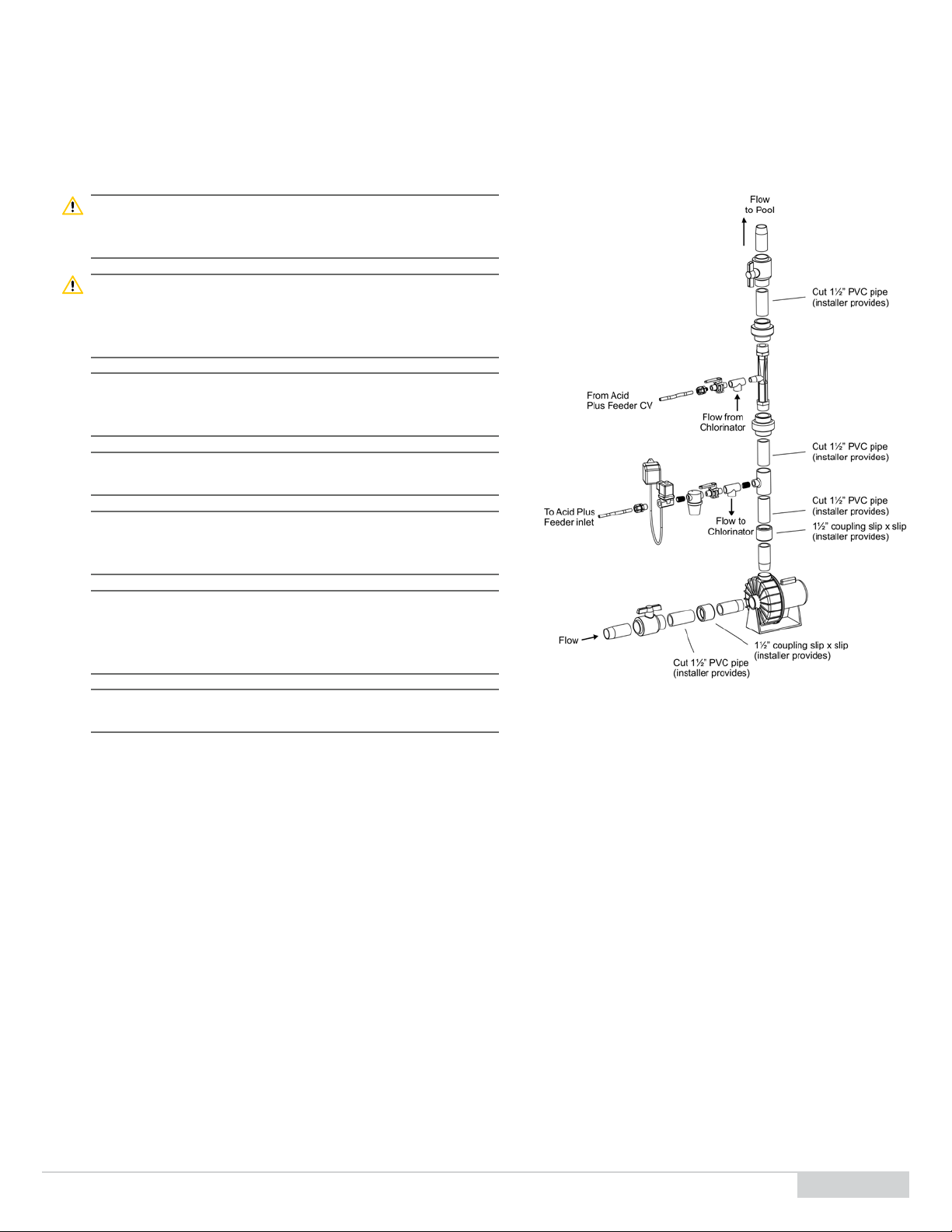
5.1 Install Booster Pump- Venturi Loop
Downstream of your pool lter(s), connect the booster pump sucon
and venturi outlet 1 ½” piping: See Figure 3
Danger: Shut o the pool pump and isolate the pool return piping
locaon used for the installaon to prevent excessive water
leakage.
Danger: If installing with a chlorine feeder OTHER than the Pulsar®
Precision, electrically interlocking the booster pump with
the pool pump is recommended to protect the pump from
running dry in a no ow condion.
Note: If installing with a chlorine feeder OTHER than the Pulsar®
Precision, connect the booster pump directly to the facility
115/230 VAC power source.
Note: Refer to the process ow diagram in secon 2.2 for proper
locaon of system piping connecons
Note: If installing WITH a Pulsar® Precision chlorine feeder, use ½”
threaded tees to split the the ow to the feeder inlet and
venturi sucon from the feeder discharge
Note: If installing WITH a Pulsar® Precision chlorine feeder, refer to
secon 5 of the Pulsar® Precision Operaon and Installaon
manual for booster pump, venturi, and ow switch
installaon instrucons
Note: Saddle clamps or tee’s can be used as an alternave for a
cleaner installaon.
1. Drill and tap two 1 ½” NPT holes that will be used for the booster pump inlet and venturi outlet, respecvely.
2. Since not all pipes run full, for horizontal pipe, drill the holes on the side or boom.
3. Cut in half the 12” x 1 ½” PVC threaded nipple provided in the installaon kit.
4. Apply plumbers’ tape to the threads of the two nipples and thread the nipples into the 1 ½” tapped holes.
5. Add silicon seal bead around the thread connecon to help make a waterproof seal.
6. Take the 1 ½” ball valves and glue them onto the 1 ½” nipples. These are the isolaon valves to the inlet and outlet of the booster pump
and venturi.
7. Glue the 2” x 1 ½” reducer bushings to the pump union tailpieces and connect to the booster pump sucon and discharge.
8. Apply plumbers tape on the venturi threads and thread the 1 ½” unions to both ends of the venturi.
9. Complete the 1 ½” piping run from the inlet nipple to the booster pump sucon (image)
10. Connect the discharge of the booster pump with the 1 ½” to ½” reducer bushing and the 1 ½” venturi ensuring the venturi is oriented in
the direcon of ow.
11. Complete the 1 ½” piping run from the outlet of the venturi to the outlet nipple on the pool return using as few 90° elbows as praccable.
The use of 45° elbows in place of 90° elbows are preferred to minimize backpressure on the venturi outlet.
Figure3. 1 ½” booster pump and venturi assembly
Pulsar® Acid Plus System Operaon and Installaon Manual (Model PS-1AP) Rev 1.0 06/2022
12
5.2 FeederSetup–DischargeValve(DV)AssemblytoVenturiSucon
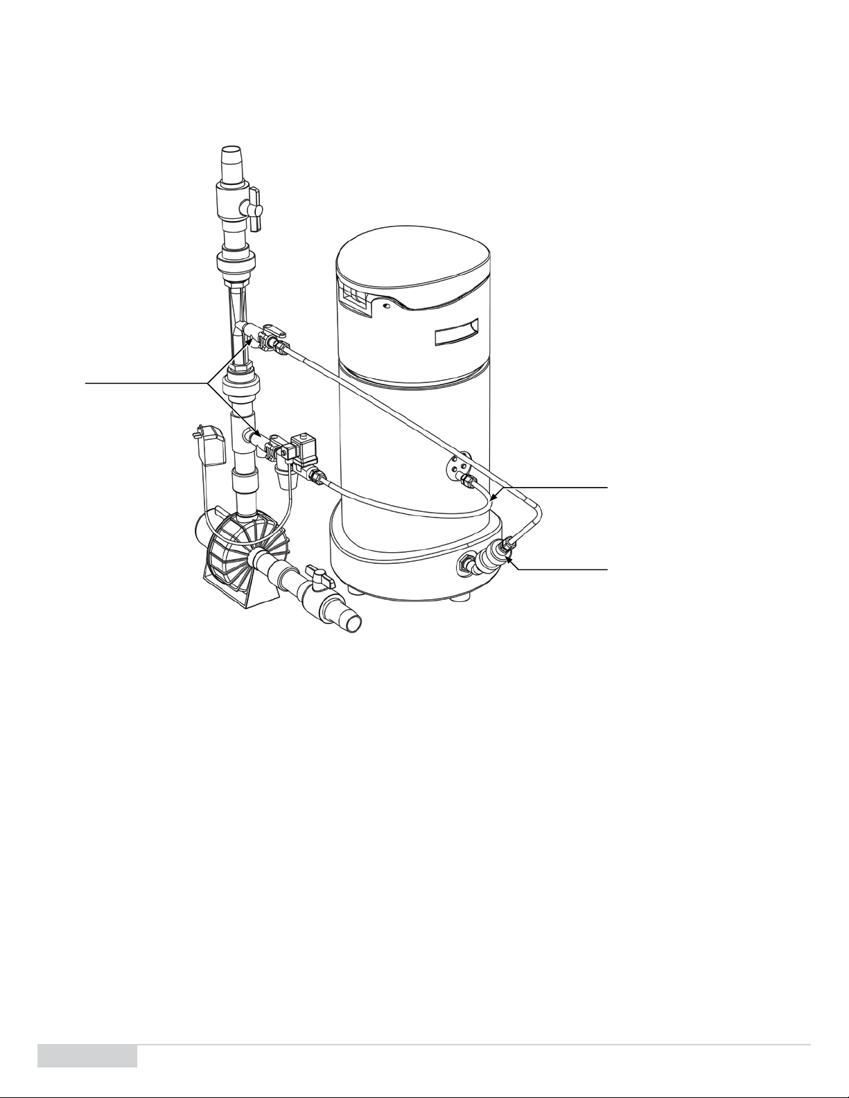
To connect the feeder discharge to the venturi sucon, refer to Figure 3 and Figure 4.
Figure4. Feeder connecons to booster pump and venturi
1. Complete the DV assembly on the exterior base of the feeder
a. Install the 45° threaded elbow on the discharge valve threads exposed on the exterior of the feeder base. Ensure that the elbow is
pointed up.
b. Install the threaded nipple, union check valve, and tubing connector to complete the assembly
2. Complete assembly on the venturi sucon
a. If installing with the Pulsar® Precision feeder, install the ½” threaded Tee on the venturi sucon, otherwise skip this step and go to step
2b
b. Install the ½” ball valve and tubing connector
3. Esmate how much tubing is needed to make the connecon between the feeder and venturi and cut the appropriate tubing length using
tubing cuers
4. Connect the tubing to the tubing connector on the venturi sucon
Feederinlet
Oponal1/2"Tees
Ifinstallingwiththe
Pulsar®PrecisionFeeder
Feederdischarge

Pulsar® Acid Plus System Operaon and Installaon Manual (Model PS-1AP) Rev 1.0 06/2022 13
5.3 Feeder Setup – Feeder inlet line from booster pump discharge
To connect the feeder discharge to the booster pump discharge, refer to Figure 3 and Figure 4.
1. Complete assembly on the booster pump discharge prior to the venturi
a. If installing with the Pulsar® Precision feeder, install the ½” nipple and threaded Tee at the discharge of the booster pump, otherwise
skip this step and go to step 1b
b. Install the ½” ball valve, strainer, solenoid valve and tubing connector to complete the assembly
2. Complete the inlet connecon of the feeder by installing the tubing connector
3. Esmate how much tubing is needed to make the connecon between the feeder and venturi and cut the appropriate tubing length using
tubing cuers
4. Connect the feeder inlet to the booster pump discharge.
5.4 Feeder Setup if pairing with a Pulsar® Precision Chlorine Feeder
Refer to the Pulsar® Precision operaon and installaon manual for chlorine feeder installaon instrucons
Note: When using the same booster pump and venturi as the Precision feeder as shown
in the schemac in gure 1, the booster pump should be wired through the Pulsar®
Precision control box to benet from the safety features of the ow switch. Refer
to secon 5.6 and 5.7 of the Precision manual for instrucons.
Note: When using the same booster pump and venturi as the Precision feeder, set the
booster pump to Always On by seng dip switch 4 to OFF in the control box. This
will allow the booster pump to provide constant ow to both feeders, except for
when there is a No Flow condion in the pool recirculaon piping.
Note: With an average of 30 gpm through the 1 ½” pipe and 3 gpm at the sucon, the
move ow through the venturi provides roughly a 10 to 1 diluon rao of water to
chemical soluon injected at the venturi sucon. Addional diluon occurs when
the soluon is introduced at the main pool piping.
Note: For any custom installaon inquiries, such as using two venturis or a dierent
booster pump, contact your sales rep for support.
1. Refer to the schemac in Figure 1 and booster pump and venturi assembly (Figure 3 and Figure 4) for guidance
2. If installing the Pulsar® Acid Plus dry acid feeder with a Pulsar® Precision chlorine feeder, add the oponal ½” threaded Tees on the booster
pump discharge and venturi sucon as shown in Figure 3 and Figure 4.
3. The Tees will allow the use of both feeders on one booster pump and venturi bypass.

Pulsar® Acid Plus System Operaon and Installaon Manual (Model PS-1AP) Rev 1.0 06/2022
14
5.5 Wire the Booster Pump to facility power (Generic Chlorine Feeder Use)
Using a cered electrician, connect the booster pump to facility power using
12 AWG or bigger wire.
Warning: Risk of dangerous or fatal electric shock. Be sure that power to the
motor circuit is o before working on wiring, wiring connecons,
or the motor. Re-install the motor end cover and all other wiring
covers before turning on the power.
Note: Be sure no other lights or equipment are on the same circuit as the
booster pump.
Note: Use Ground Fault Circuit Interrupter (GFCI) as a master on-o
switch.
Note: If installing WITH a Pulsar® Precision chlorine feeder, wire the
booster pump directly to the feeder control box to benet from
safety and energy saving features.
1. Remove the booster pump motor end cover to expose the pump’s dual-
voltage selector, Figure 5.
2. If you have 230 V motor supply voltage, conrm that the plug is set for 230 V. The arrow on the plug will point to the 230 V posion, which
is the default posion of the pump (the plug only connects with one prong in this posion).
3. If you have 115 V supply, pull the plug straight up and place it on the two brass prongs so that the arrow points to the 115 V posion.
4. Replace the booster pump end cover to complete the booster pump wiring.
5.6 Prime the System
Allow pool water to enter the 1 ½” and ½” piping and tubing to conrm overall water ghtness
1. Open the 1 ½” inlet ball valve at the booster pump sucon and allow water to enter checking for leaks
2. Slowly crack open the booster pump discharge union allowing water to ow out conrming that the booster pump is fully primed.
3. Reconnect and ghten the discharge union.
4. Open the 1 ½” outlet ball valve fully priming the enre booster pump / venturi loop.
5. Open the ½” gray inlet and outlet feeder ball valves allowing water to reach the feeder(s).
6. Check for leaks at the booster pump and venturi loop, feeder(s) and ow switch, if installed, and redo any leaking connecons.
Figure5. Dual-voltage selector

Pulsar® Acid Plus System Operaon and Installaon Manual (Model PS-1AP) Rev 1.0 06/2022 15
6 Post-InstallaonInstrucons
6.1 Post-InstallaonChecklist
Before rst-me startup of the feeder, check:
Table2. Post-InstallaonChecklist
ItemNo Check Completed?
1. Is there any residual debris (plasc shavings, screws, and so on) inside the soluon tank?
2. Has the booster pump been fully primed?
3. Are all electrical lines secure and not a tripping hazard?
4. Are all exposed electrical and instrument lines protected and do they meet eld condions?
5. Does the booster pump motor plug line up to the correct voltage supply?
6. If using with a Pulsar® Precision feeder, is the control box cover closed and screws securely ghtened?
7. If the booster pump is wired to a Pulsar® Precision control box, is dip switch 4 set to the o posion for Always On
operaon?
8. Are all ngs and unions ghtened to prevent leaks?
9. Are ow direconal arrows pointed in the correct direcon of ow on the venturi, solenoid valves, and check valve?
10. Are Tees at the booster pump discharge and venturi sucon used if installing with a Pulsar® Precision chlorine
feeder as shown in gures 1, 3, and 4?

Pulsar® Acid Plus System Operaon and Installaon Manual (Model PS-1AP) Rev 1.0 06/2022
16
6.2 System Startup
Note: Before starng up the equipment, ensure that the Post-Installaon checklist has
been completed.
6.2.1 System Power Up
Aer compleng the post-installaon checklist:
1. Once the system is fully primed, ensure the 1 ½” booster pump and venturi inlet and outlet ball valves are in the fully open posion.
2. Ensure the ½” feeder inlet and outlet ball valves coming from the booster pump and venturi are in the fully open posion
3. Energize and power on the booster pump
Note: Refer to the booster pump user manual for troubleshoong any issues
4. With the solenoid valve plugged into the chemical controller pH control output, test the solenoid and feeder operaon
Note: Refer to the chemical controller user manual to manually call for pH down
5. Check that the solenoid valve energizes. There should be an audible click that occurs when the valve receives power and opens.
6. With the solenoid valve energized, open the hopper lid, ensure that water is coming out of the three blue spray nozzles, and the nozzles
are facing up
7. With water connuing to come out of the spray nozzles, ensure that the DV and feeder discharge is operang correctly, and water is pulled
out of the base by the venturi. This can be visually conrmed if using the clear ½” discharge tubing
8. If the feeder, booster pump, and venturi appear to be operang correctly, stop the chemical controller pH control output,
9. Shut the ½” feeder inlet and outlet ball valves coming from the booster pump and venturi to isolate the feeder and prepare the feeder for
operaon
6.2.2 FeederPreparaon
1. Open hopper lid.
2. Place meshed grid into the hopper.
3. Put on the appropriate PPE: long sleeved clothing, rubber gloves, apron, dust mask, and safety glasses.
Danger: Use suitable personal protecve equipment (PPE) at all mes to avoid physical
contact with sodium bisulfate. Failure to do so may result in death or serious injury.
See the Safety Data Sheet for addional informaon and precauons regarding the
proper handling of Pulsar® pH Down (+4).
Danger: Fire or explosion could result from contaminaon or use of any other chemical
compound! When lling the hopper with sodium bisulfate acid, use a scoop
dedicated for this purpose.
4. Use a dedicated scooper to add Pulsar® pH Down (+4) into the hopper on top of the meshed grid.
5. Plug the solenoid valve power supply into the pH control output of the chemical controller
6. Close hopper lid.

Pulsar® Acid Plus System Operaon and Installaon Manual (Model PS-1AP) Rev 1.0 06/2022 17
7 OperaonInstrucons
Warning: The use of Pulsar® pH Down (+4) dry sodium bisulfate reduces the pH in a pool.
Ensure the chemical controller’s pH control output is congured for pH down
control. The use of this feeder and chemical with a pH up control conguraon will
result in over dosing acid and lowering the pH to unsafe levels.
Cauon: Use of any other chemicals other than the Pulsar® pH Down (+4) for use with this
feeder shall void this warranty.
Note: When using the same booster pump and venturi as the Precision feeder, set the
booster pump to Always On by seng dip switch 4 to OFF in the control box. This
will allow the booster pump to provide constant ow to both feeders, except for
when there is a No Flow condion in the pool recirculaon piping.
To operate the Pulsar® Acid Plus Feeder:
1. Open the ½” feeder inlet and outlet ball valves coming from the booster pump and venturi
2. Ensure the feed solenoid valve is plugged into the chemical controller pH control output for pH down
3. Ensure there is Pulsar® pH Down (+4) in the hopper on the meshed grid
4. Ensure the booster pump Is powered on
a. Ensure the booster pump is powered on at the facility breaker if using with a chlorine feeder OTHER than a Pulsar® Precision.
b. Ensure the Pulsar® Precision control box is powered on and in ORP mode if the booster pump is wired directly into the control box.
5. Set the desired pH setpoint on the chemical controller and follow the chemical controller user manual for addional instrucons on pH
control automaon.
6. When a pH reducon signal is sent by the chemical controller, the feed solenoid valve will energize and open, and a feed cycle will start
creang acid soluon for injecon into the pool
7. Once pH reducon demand terminates, the solenoid valve will de-energize and shut, and the feeder will stop creang acid soluon unl
the next pH reducon demand is sent.
8. Refer to 6.2.2 Feeder Preparaon to rell hopper with chemical as necessary

Pulsar® Acid Plus System Operaon and Installaon Manual (Model PS-1AP) Rev 1.0 06/2022
18
8 PreventaveMaintenance
8.1 PreventaveMaintenanceSchedule
Complete each of the following tasks during the rst week of each month.
Table3. MonthlyMaintenance
AconNeeded MaintenanceProcess TimetoComplete
Change/clean basket See Secon 8.3 on page 20.
Inspect inlet and
outlet plumbing
ngs
Verify that there are no leaks at any of the inlet and outlet ½" feeder ngs and 1 ½" booster
pump and venturi piping and ngs, including the booster pump itself.
1. Close all isolaon ball valves and re-plumb / replace any leaking piping and ngs.
2. If leaking is observed at the pump motor, the pump sha seal and impeller will have to be
replaced. Refer to the booster pump manual troubleshoong guide and repair parts list for
addional informaon.
2 min
Inspect booster
pump
1. Visually check for leaks on and around the pump, including the sucon and discharge piping
and ngs.
2. Close inlet and outlet 1 ½" ball valves and ghten or replace any leaking ngs.
3. If leaking observed at the pump motor, the pump sha seal and impeller is likely burned.
4. Refer to the booster pump manual troubleshoong guide and repair parts list for addional
informaon.
Inspect inlet line
strainer assembly
1. With pressure in the line, visually inspect the strainer basket for leaks. Replace enre basket
assembly if leaking.
2. Close inlet ball valve
3. Remove strainer basket and visually inspect for cracks and debris.
4. Remove strainer screen and wash it out prior to replacing it back into the basket.
5. If screen appears damaged or has a hole in it, replace with a new screen.
6. Re-install the strainer basket back into the strainer body
10 - 15 min
Inspect discharge
check valve
1. Close the outlet ball valve
2. Open the lower le and right base covers and unscrew the check valve unions to remove the
check valve body
3. Disassemble the check valve and inspect for debris. Clean if necessary.
4. Visually check the seal for corrosion. If seal is corroded, replace check valve
5. Re-assemble the check valve body ensuring ensuring the seal is on the side of the ball.
6. Replace the check valve body back onto the unions, ensure arrow points away from the
feeder.
10 min
Inspect reservoir
tank
Visually inspect soluon reservoir and ensure that there is no debris, i.e., dirt or contaminaon,
on the high-level switch or the discharge valve (DV) assembly including the DV oat, and arm.
Debris on the level switch will prevent posive nocaon of a high-level event. Verify level
switch operaon by liing the switch and conrming the alert indicator light turns on.
Debris on the DV oat or arm can interfere with feeder discharge operaon. Remove debris
as needed.
5 min

Pulsar® Acid Plus System Operaon and Installaon Manual (Model PS-1AP) Rev 1.0 06/2022 19
Complete the following task during the rst week of January and the rst week of July.
Note: Maintenance that prevents the discharge line from clogging is crical to feeder
operaon.
Table4. SemiannualMaintenance
AconNeeded MaintenanceProcess TimetoComplete
Inspect Venturi (If
using with a Pulsar®
Precision Feeder)
1. Close inlet and outlet 1 ½” ball valves to the booster pump sucon and venturi outlet
2. Close inlet and outlet ½” ball valves to the feeder
3. Disconnect feeder discharge tubing from the venturi
4. Remove the venturi via the 1 ½” unions and visually inspect and verify it is not clogged with
scale build up.
5. If scale buildup is found, refer to cleaning instrucons in the Pulsar® Precision Manual,
Secon 8.2
2 - 5 min
Inspect solenoid
valve
During feed or wash cycle, if solenoid valves are hot to the touch, consider rebuilding or replacing
the valve. If solenoid makes a raling noise when energized, consider replacing the valve.
2 min

Pulsar® Acid Plus System Operaon and Installaon Manual (Model PS-1AP) Rev 1.0 06/2022
20
8.3 Cleaning Procedures
Note: Pulsar® pH Down (+4) chemical is 100% dissolvable and as such, no residue, scaling,
or solids are developed as part of the dissoluon process. This allows the feeder to
run clean during normal operaon with no major oine cleaning requirements.
Note: Inspect the feeder regularly in accordance with the preventave maintenance
schedule in secon 7.1. If external debris or contaminaon is found within the
feeder or feeder components, follow the maintenance procedures outlined in the
table. If addional cleaning is needed or desired due to excessive debris found,
follow the cleaning steps below.
8.3.1 Equipment Needed
PPE
Rubber gloves
Apron
Safety glasses
Long sleeved clothing
Hose (for oine cleaning)
8.3.2 CleaningInstrucons
1. Allow feeder to consume as much of the chemical in the hopper as possible before geng started .
2. When hopper is empty, shut the inlet ½” ball valve to stop all water ow into the feeder.
3. With the booster pump and venturi sll running and discharge ball valve sll open, take a hose and spray down the inside of the hopper to
clean o all remaining acid residue and debris
4. Remove the hopper from the base.
5. Take a hose and rinse the inside of the base and clean o any remaining acid residue and debris.
6. Ensure all soluon or contaminaon is pulled out of the base by the venturi
7. Repeat steps 3 to 6 as needed to clean the feeder and discharge tubing
8. Open the ½” inlet valves to return the feeder to normal operaon.
This manual suits for next models
1
Table of contents
Other Innovative Water Care Swimming Pool Filter manuals

Popular Swimming Pool Filter manuals by other brands


Evoqua
Evoqua BLU-SENTINEL SE Short operating instructions

AquaVac
AquaVac fully automatic pool cleaner user guide

EHEIM
EHEIM SKIM MARINE 800 operating instructions

Pentair
Pentair TRITON installation guide

weltico
weltico A600 ELEGANCE Assembly instructions

SMC Networks
SMC Networks AutoChlor SMC20TA instruction manual