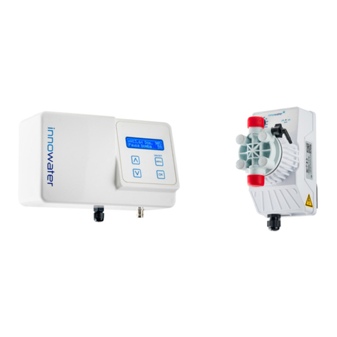
Innowater pH BASIC User manual

pH BASIC
Operating Manual

WARNINGS
Before carrying out any installation or maintenance of the pH-Basic, disconnect it
from the mains power supply.
This appliance is not intended for use by persons (including children) that lack ex-
perience and knowledge, unless they have been given supervision or instruction
concerning use of the appliance by a responsible person.
The installation of this device should be carried out by a qualified person.
The pH-Basic device should be located in the correct pool zone and connected to
supply via a power outlet that is protected by a residual current device (RCD) hav-
ing a rated residual operating current not exceeding 30mA.
The power outlet should have a degree of protection suitable for the pool zone
Ensure that equipotential bonding of all parts of the pool installation is carried out.
During the installation phase of the pH Basic, check the following:
• the voltage of the power supply must to the voltage indicated on the side
of the appliance
• the injection point pressure must be lower than 1.5 Bar
• the peristaltic pump's protection cover must be correctly fitted
• the suction tube must be immersed in the corrective solution container
with the suction tube also connected to the peristaltic pump (left side).
• the injection tube must be connected on one side to the peristaltic pump
(right side) and on the other side to the pool return pipe via the injection
valve.
Innowater Tratamientos Integrales del Agua S.L. will not be held liable for the use
of this device with inappropriate products.

Ver 05/19 2 pH Basic
DESCRIPTION
The pH Basic works to correct the pH level of your pool by injecting corrective acid
solution in the circuit. The device monitors the pH continuously by means of its pH
sensor and sends a dosing signal to the pump which will, in turn, injects acid in the
pool when needed.
The device will control the speed of the pump depending on the measurement of
the probe and the setpoints programmed. To avoid excessive dosage related to
measuring delays, the pump will alternate start/pause periods in cycles of 100
seconds.
1. BNC socket for container level switch
2. BNC socket for pH probe
3. 230 Vac power supply
4. Connection for suction tube
5. Connection for injection tube
6. LCD Display
7. Buttons

pH Basic 3
MECHANICAL AND HYDRAULIC INSTALLATION
During installation ensure that the mains cable is disconnected from
the power supply.
Acids are very corrosive and can harm you eyes, skin and airways.
When working with pH correctors necessary caution and preventive
measures should be taken. Always wear safety googles, gloves and
clothing.
Acid container. We strongly recommend to place the acid container outside
the filter shed. If it is not possible, ensure the adequate ventilation is
provided and place the container as far from metallic and electronic
equipment as possible and NEVER underneath the pump or other device.
pH-Basic. Install the device on the wall in an easy to access location using
the bracket provided. Before attaching the bracket to the pump, use the
bracket to mark in the wall the location of the holes you will need to make
for the screws. Choose a location close to the injection point.
Injection. Install the clamp saddle provided in the return pipe after all other
equipment (pump, filter, heater, chlorinator etc.). It should be the last
element on the return line. Install the injection one way valve on the clamp
saddle. Use Teflon tape to seal the thread. Connect the injection rigid
tubbing (opaque) to the valve.
Connect the other end of the injection tube (opaque) to the injection fitting
(right side) of the peristaltic pump.
Suction. Connect the flexible suction tube (transparent) to the injection
fitting (left side) of the peristaltic pump.
Use a length of tube long enough to reach from the acid container to the
peristaltic pump and feed the tube through the black rubber grommet in
the ‘anti-fume’ cap. Once the cap is on the tube, fit the suction filter to the
suction tube and place the suction line into the acid container. Screw the anti
fume cap down into position.
Probe. Install pH probe preferably after the filter. If there is a salt water
chlorinator, the probe must be installed before the cell and as far as possible
from it. Try to choose a point in the circuit that never gets empty of water,
because the probe deteriorates very quickly when dry.
ELECTRICAL INSTALATION
Power supply
Connect the 230 VAC power supply cable plug (3) into a mains power point
provided with a protective earthing conductor (PE)

Ver 05/19 4 pH Basic
OPERATION, CONFIGURATION AND CALIBRATION
Main Screen
Main screen provides information about the current state of the device:
On the upper left of the screen is shows the pH value measured by the probe, and
on the right the percentage of dosing depending on setpoints configuration.
Priming
To start the pump manually just press “OK” in the main screen and keep on pushing
it the time enough until the liquid reaches the injection valve.
Main menu
Press Menu to access to the main menu. Use the arrows to scroll the different
functions. Press OK to enter in each sub-menu.
1. pH Configuration
1.1. Set points
Enter with OK key. It will show the following screen:
The calculation of the dosage is made by establishing the two setpoints, A and B,
and the relative volume of dosage that is required in each of these points.
- When the pH value is below the lower set point, the pump will not dose acid.
- When the pH is between both points, the chlorinator will send a proportional signal
defined by both points. For example, in the case of the figure, if pH is at 8, the
pump will dose al 40%.
- When the pH is above the upper setpoint, the pump will dose to the fixed volume
defined for the upper point. In the case of the figure, 80%.
pH Configuration
1 Set Points
A: pH 7.0 0%
B: pH 9.0 80%
pH 7.0 Dos. 0%

pH Basic 5
You can set both point and choose the percentage of dosage for each of them. To
do this, press the cursor with the MENU key in the parameter you want to modify
and act with the arrows to change the value. Press OK to save the data and exit
the sub-menu.
By choosing the set points you will be defining at the same time the required
dosing volume and the response delay after dosing, both of them depending on the
size of your pool. For example, if your pool has a high volume you should establish
high percentages of dosing. The response time in the pH measurement of your pool
can be considered when setting point A of the setpoint, stopping the dosage
before reaching the desired pH value. For example, to obtain a pH = 7.0 and avoid
overdosing, set the dosage stop in a higher value:
A: pH 7,2 0%
Each pool needs more or less acid, as they are more or less reactive to the dosage;
at the beginning at least, you may need to correct the setpoints several times.
1.2.— 1.3. pH probe Calibration
pH probes require a calibration before their first use and then they need to be
calibrated periodically. This is because different probes have different responses
and the response of the same probe inevitably varies with time.
The calibration consists of measuring the response of the probe introducing it in
two different buffer solutions in order to deduct the pH of any other solution, in our
case, the pH of the pool water.
The calibration of the probe is carried out using the two buffer solutions supplied
(pH4 and pH7) and entering the submenus “2 Cal pH4” and “3 Cal pH7”
respectively.
Enter the sub-menu 2 Cal pH4 by pressing OK key, it will show the following
screen:
The value next to Lec (on the left) indicates the current pH value measured by the
probe.
pH Configuration
2 Cal pH 4
pH Configuration
3 Cal pH 7
pH 4 Calibration
Lec: 4.05 4.00
pH 7 Calibration
Lec: 7.05 7.00

Ver 05/19 6 pH Basic
The value on the right indicates the buffer solution we are using. You can adjust
this value using the arrows to adapt it to the temperature and the sample used.
Insert the probe in the 4 pH buffer calibration, remove it slightly with the probe
and wait for a stable reading value to be reached.
Once the reading value has stabilized press OK key to save calibration and exit the
sub-menu.
Next, remove probe the probe from the pH4 buffer solution, rinse its bottom with
clean water and shake gently to remove an excess of water.
Repeat the procedure above with the pH7 buffer solution and submenu “3 Cal pH
7”
Note: During calibration, if value measured by the probe (Lec), differs in more
than 2 units from the theoretical of the buffer solution (pH4 and pH7), data
calibration won´t be saved and it will go back to factory values.
For example, if the reading value (Lec) is 6,05 while calibrating with pH4 solution.
1.4. Factory calibration
In submenu 5 Factory calib, gives you the possibility to reset general calibration
parameters that correspond, approximately, with those of a new probe and which
are the ones programmed by the chlorinator form factory values. This can be
useful if you have saved successive calibrations and do not have the buffer solution
for a correct calibration.
Press OK to enter the sub menu 5 Factory calib, it will show the following screen.
pH Configuration
5 Factory calib.
Factory Calib.?
yes:OK exit:MENU

pH Basic 7
1.5. Dosing alarm
Press OK to enter. To activate or deactivate, scroll with arrow keys up or down to
ON or OFF. Then, press menu key to set the amount of time desired (up to 20
minutes).
2. Language
Press OK to enter. Scroll with arrow keys and choose the language. Then press
OK.
3. Contrast LCD
Press OK to enter. Scroll with arrow keys and choose the contrast level. Then press
OK.
TECHNICAL DATA
Power supply 100-240 VAC 50-60 Hz
Consumption 12 W
Pump Flow rate 1.5 l/h
Maximum pressure 1.5 bar
Dimensions (mm) 220 x 130 x 85
pH Configuration
6 Dosing alarm
Dosing Alarm OFF
Max. Dos. 20 min
MAIN MENU
2 Language
Choose language
English
MAIN MENU
3 Contrast LCD
Contrast
- ■ ■ ■ ■ +

Ver 05/19 8 pH Basic
Other Innowater Controllers manuals
