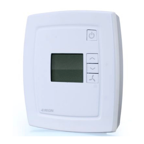
Regin REGIO EEDO User manual

en
WE TAKE BUILDING
AUTOMATION PERSONALLY
MANUAL
REGIOEEDO

Rev. D, 2020-01-28
THANK YOU FOR CHOOSING REGIN!
Ever since Regin was established in 1947, we have developed and mar eted products and systems that create good
levels of indoor comfort. Today, we are an important player with one of the mar et's broadest ranges for building
automation.
Our goal is to ma e real estates in the world more energy efficient. Regin is an international group and our products
sells in over 90 countries. Than s to our global presence with strong local representation, we are well aware of the
requirements of the mar et, as well as of how our products and systems function under the most variable conditions.
Every year, Regin ma es substantial investments in the development of our systems and HVAC-products.
DISCLAIMER
The information in this manual has been carefully chec ed and is believed to be correct. Regin ma es no warranties
about the contents of this manual and users are requested to report errors and discrepancies to Regin, so that
corrections may be made in future editions. The information in this document is subject to change without prior
notification.
Some product names mentioned in this document are used for identification purposes only and may be the registered
trademar s of their respective companies.
© AB Regin. All rights reserved.

Table of Contents
Introduction .................................................................................................................................5
1.1 About this manual...............................................................................................................5
2 Control functions.........................................................................................................................6
2.1 Controller mode .................................................................................................................6
2.1.1 Heating.................................................................................................................6
2.1.2 Heating + Heating .................................................................................................7
2.1.3 Heating + Cooling .................................................................................................8
2.1.4 Cooling.................................................................................................................9
2.1.5 Heating/Cooling (change-over) .............................................................................10
2.1.6 Heating + Heating/Cooling (change-over)..............................................................12
2.1.7 Heating + VAV ...................................................................................................14
2.1.8 Cooling + VAV ...................................................................................................15
2.1.9 VAV ..................................................................................................................17
2.1.10 Heating + Cooling + VAV ....................................................................................17
2.2 Maximum and minimum limits for heating and cooling output..............................................19
2.3 Change-over.....................................................................................................................20
2.3.1 Change-over detection .........................................................................................21
2.4 Controller state.................................................................................................................22
2.4.1 Control behaviour ...............................................................................................23
2.4.2 Configuration settings ..........................................................................................25
2.4.3 State changes.......................................................................................................26
2.5 Fan control .......................................................................................................................29
2.5.1 EC fan control.....................................................................................................30
2.5.2 3-speed fan control ..............................................................................................32
2.5.3 Fan boost ............................................................................................................34
2.5.4 Fan ic -start.......................................................................................................36
2.5.5 Fan afterblow ......................................................................................................37
2.6 VAV control.....................................................................................................................37
2.7 Forced ventilation .............................................................................................................40
2.8 Presence detection ............................................................................................................43
2.9 CO2control......................................................................................................................45
3 Room unit..................................................................................................................................47
3.1 Model overview and user interface description .....................................................................47
3.2 Room units without display ...............................................................................................49
3.2.1 Selecting a fan speed ............................................................................................49
3.2.2 Performing a setpoint adjustment ..........................................................................49
3.2.3 Putting the room HVAC system in a comfort/energy saving mode or increasing
the airflow ..........................................................................................................49
3.2.4 LED indications...................................................................................................49
3.3 Room units with display ....................................................................................................50
3.3.1 Selecting a fan speed ............................................................................................50
3.3.2 Performing a setpoint adjustment ..........................................................................50
3.3.3 Putting the room HVAC system in a comfort/energy saving mode or increasing
the airflow ..........................................................................................................51
3.3.4 Display indications...............................................................................................51
3.3.5 Basic controller configuration via the display ..........................................................52
3.3.6 Parameter menu access.........................................................................................53
3.3.7 Display bac ground lighting..................................................................................53
3.3.8 ED-RU-DOS functions ........................................................................................53
3.4 Communication LED........................................................................................................54
3.5 Enable or disable buttons/switch and nob ..........................................................................54
3.6 Wiring .............................................................................................................................54
3.7 Configuration settings........................................................................................................55
3.7.1 General...............................................................................................................55
3.7.2 Max setpoint adjustment ......................................................................................55
3.7.3 Display ...............................................................................................................55

Table of Contents
3.7.4 Buttons/switch and nob ......................................................................................56
4 Inputs / Outputs.........................................................................................................................57
5 Setpoint .....................................................................................................................................59
5.1 Active setpoint .................................................................................................................59
5.2 Setpoint adjustment ..........................................................................................................60
6 Controller connections and wiring diagrams ..............................................................................6
7 LED status indications ................................................................................................................65
8 Mounting ...................................................................................................................................66
8.1 DIN rail mounting inside a cabinet......................................................................................66
8.2 Wall Mounting .................................................................................................................66
9 Maintenance and service ............................................................................................................69
9.1 Changing the battery.........................................................................................................69
9.2 Changing the fuse .............................................................................................................69
9.3 Resetting the application memory.......................................................................................70
Appendix A Technical data..........................................................................................................7
A.1 General data.....................................................................................................................71
A.2 Inputs ..............................................................................................................................71
A.3 Outputs ...........................................................................................................................71
A.4 RS485 communication port 1.............................................................................................72
A.5 RS485 communication port 2.............................................................................................72
A.6 Ethernet communication port ............................................................................................72
Appendix B Room unit display parameter lists .............................................................................73
B.1 CTRL ..............................................................................................................................73
B.2 SYS .................................................................................................................................73
B.3 ACTR..............................................................................................................................74
B.4 FAN ................................................................................................................................75
B.5 M/AT ..............................................................................................................................76
B.6 HMI ................................................................................................................................77
B.7 IO ...................................................................................................................................78
B.8 ALAM .............................................................................................................................79
Appendix C Modbus signal lists....................................................................................................8
C.1 Coil status registers ...........................................................................................................81
C.2 Input registers...................................................................................................................83
C.3 Holding registers...............................................................................................................85
C.4 Input status registers..........................................................................................................95
Appendix D BACnet signal lists....................................................................................................98
D.1 Multistate values...............................................................................................................98
D.2 Binary values ..................................................................................................................101
D.3 Analog values .................................................................................................................103

Introduction
Introduction
RegioEedo is a 230 V AC room controller with a pre-programmed software application for fan coils. The
controller provides built-in communication via EXOline, Modbus, or BACnet for integration in EXOscada
or other SCADA systems. The controller is fast and easy to configure and commission using Regin's free
Application tool software, and it connects seamlessly to the room units in Regin’s ED-RU… series. The
controller is installed in a ceiling void by using a baseplate with terminal protection covers, or on a DIN rail
inside a cabinet.
. About this manual
This manual provides descriptions of the RegioEedo controller functions, as well as hardware-related
information concerning controller connections, wiring, mounting, maintenance and service, and so on.
RegioEedo is configured and commissioned by using Regin's Application tool software. The controller
functions and their configuration options are therefore described in an Application tool context.
The manual has the following high-level section structure:
✓Sections 2-5 contain descriptions of and configuration information for controller functions, such as:
✓Heating, cooling, and variable air volume (VAV) controller modes
✓Controller states
✓Fan control
✓CO2control
✓Presence detection
✓Change-over
✓Sections 6-9 contain hardware-related information topics, such as:
✓Controller connections and wiring diagrams
✓LED status indications
✓Mounting
✓Maintenance and service
✓The Appendix sections contain the following information:
✓Technical data
✓Room unit display parameter lists
✓Modbus signal lists
✓BACnet singal lists
Special text formats used in the manual:
NNoottee!! This box and symbol is used to show useful tips and tricks.
CCaauuttiioonn!! This type of text and symbol is used to show cautions.
WWaarrnniinngg!! This type of text and symbol is used to show warnings.
RegioEedo manual, Rev. D 5

Control functions
2 Control functions
This section contains descriptions of and configuration information for the controller's basic control
functions.
2. Controller mode
The controller mode function enables the controller to support control of various room HVAC systems, that
is, different combinations of heating, cooling, and variable air volume (VAV) devices that are part of a room.
The controller provides the following 10 selectable controller modes:
✓Heating
✓Heating + Heating
✓Heating + Cooling
✓Cooling
✓Heating/Cooling (change-over)
✓Heating + Heating/Cooling (change-over)
✓Heating + VAV
✓Cooling + VAV
✓VAV
✓Heating + Cooling + VAV
Based on the selected controller mode, the controller outputs one or multiple control signal sequences,
denoted Y1, Y2, and Y3. The signal sequences control the heating, cooling, and VAV devices in the room,
and are assigned to the different controller outputs via configuration.
Figure 2-1 shows the drop down that is used to select a controller mode in Application tool.
Figure 2-1 Controller mode selection in Application tool.
2. . Heating
This controller mode is suitable for room HVAC systems that use a radiator or fan coil as heating device.
The controller acts as a heating controller and regulates based on the heating setpoint and the current room
temperature.
6 RegioEedo manual, Rev. D

Control functions
The controller is always in heating mode and outputs a heating signal, Y1, that is configured on the controller
outputs by using the configuration values listed in Table 2-1.
Maximum and minimum limits for the output signal can be set, see section 2.2.
Table 2-1 Controller output configuration values and controller output types.
Output signal Controller output configuration value Controller output type
Y1 Heating Analog
Heating valve, increase
Heating valve, decrease
Digital
Digital
Heating valve, thermal (PWM) Digital
Figure 2-2 illustrates the control behaviour for this controller mode when no maximum or minimum limits
are set.
The heating demand increases as the room temperature falls. When the room temperature falls below the
heating setpoint, Y1: Heating signal increases to respond to the heating demand. At 100% heating demand,
Y1: Heating signal reaches its maximum.
When the room temperature is higher than the heating setpoint and no heating demand exists, Y1: Heating
signal is at its minimum.
Figure 2-2 Control behaviour for the Heating controller mode.
2. .2 Heating + Heating
This controller mode is suitable for room HVAC systems that use a combination of two heating devices in
sequence, such as radiators or fan coils.
The controller acts as a heating controller and regulates based on the heating setpoint and the current room
temperature.
The controller is always in heating mode and outputs two heating signals, Y1 and Y2, in sequence that are
configured on the controller outputs by using the configuration values listed in table Table 2-2.
The Y1 and Y2 signal sequence order is configurable.
Maximum and minimum limits for the output signals can be set, see section 2.2.
Y1: Heating signal
Output
Max: 100%
Heating
setpoint
Min: 0%
Room temperature
100%0%
Heating demand
RegioEedo manual, Rev. D 7

Control functions
Table 2-2 Controller output configuration values and controller output types.
Output signal Controller output configuration value Controller output type
Y1 Heating Analog
Heating valve, increase
Heating valve, decrease
Digital
Digital
Heating valve, thermal (PWM) Digital
Y2 Heating 2 Analog
Heating valve 2, increase
Heating valve 2, decrease
Digital
Digital
Heating valve 2, thermal (PWM) Digital
Figure 2-3 illustrates the control behaviour for this controller mode when no maximum or minimum limits
are set.
The heating demand increases as the room temperature falls. When the room temperature falls below the
heating setpoint, Y1: Heating signal increases to respond to the heating demand. At 49% heating demand, Y1:
Heating signal reaches its maximum. When the room temperature falls further and the heating demand
exceeds 51%, Y2: Heating 2 signal increases while Y1: Heating signal stays at its maximum. At 100% heating
demand, Y2: Heating signal reaches its maximum.
When the room temperature is higher than the heating setpoint and no heating demand exists, both Y1:
Heating signal and Y2: Heating 2 signal are at their minimum.
Figure 2-3 Control behaviour for the Heating + Heating controller mode.
2. .3 Heating + Cooling
This controller mode is suitable for room HVAC systems that use a radiator or fan coil as heating device, and
a fan coil or chilled beam as cooling device.
The controller acts as a heating and cooling controller and regulates based on the heating setpoint, cooling
setpoint, and the current room temperature.
The temperature range between the heating and cooling setpoints is defined as the deadband. The controller
is in heating mode when the room temperature is lower than [heating setpoint plus half the deadband], and
in cooling mode when the room temperature is higher than [cooling setpoint minus half the deadband].
When in heating mode, the controller outputs a heating signal, Y1, that is configured on the controller
outputs by using the values listed in Table 2-3.
Y2: Heating 2 signal
Output
Max: 100%
Heating
setpoint
Min: 0%
Room temperature
Heating demand
100%51%49%0%
Y1: Heating signal
8 RegioEedo manual, Rev. D

Control functions
When in cooling mode, the controller outputs a cooling signal, Y2, that is configured on the controller
outputs by using the values listed in Table 2-3.
Maximum and minimum limits for the output signals can be set, see section 2.2.
Table 2-3 Controller output configuration values and controller output types.
Output signal Controller output configuration value Controller output type
Y1 Heating Analog
Heating valve, increase
Heating valve, decrease
Digital
Digital
Heating valve, thermal (PWM) Digital
Y2 Cooling Analog
Cooling valve, increase
Cooling valve, decrease
Digital
Digital
Cooling valve, thermal (PWM) Digital
Y1 + Y2 6-way valve Analog
6-way valve, increase
6-way valve, decrease
Digital
Digital
Figure 2-4 illustrates the control behaviour for this controller mode when no maximum or minimum limits
are set.
The heating demand increases as the room temperature falls. When the room temperature falls below the
heating setpoint, Y1: Heating signal increases to respond to the heating demand. At 100% heating demand,
Y1: Heating signal reaches its maximum. When the room temperature is in the range between the heating
setpoint and the deadband centre, and no heating demand exists, Y1: Heating signal is at its minimum.
The cooling demand increases as the room temperature rises. When the room temperature rises above the
cooling setpoint, Y2: Cooling signal increases to respond to the cooling demand. At 100% cooling demand,
Y2: Cooling signal reaches its maximum. When the room temperature is in the range between the cooling
setpoint and the deadband centre, and no cooling demand exists, Y2: Cooling signal is at its minimum.
Figure 2- Control behaviour for the Heating + Cooling controller mode.
2. .4 Cooling
This controller mode is suitable for room HVAC systems that use a fan coil or a chilled beam as cooling
device.
Y1: Heating signalY2: Cooling signal
Output
Max: 100%
Heating
setpoint
Cooling
setpoint
Min: 0%
Deadband
Room temperature
100%100% 0% 0%
Cooling demand
Heating demand
RegioEedo manual, Rev. D 9

Control functions
The controller acts as a cooling controller and regulates based on the cooling setpoint and the current room
temperature.
The controller is always in cooling mode and outputs a cooling signal, Y1, that is configured on the controller
outputs by using the configuration values listed in Table 2-4.
Maximum and minimum limits for the output signal can be set, see section 2.2.
Table 2- Controller output configuration values and controller output types.
Output signal Controller output configuration value Controller output type
Y1 Cooling Analog
Cooling valve, increase
Cooling valve, decrease
Digital
Digital
Cooling valve, thermal (PWM) Digital
Figure 2-5 illustrates the control behaviour for this controller mode when no maximum or minimum limits
are set.
The cooling demand increases as the room temperature rises. When the room temperature rises above the
cooling setpoint, Y1: Cooling signal increases to respond to the cooling demand. At 100% cooling demand,
Y1: Cooling signal reaches its maximum.
When the room temperature is lower than the cooling setpoint and no cooling demand exists, Y1: Cooling
signal is at its minimum.
Figure 2-5 Control behaviour for the Cooling controller mode.
2. .5 Heating/Cooling (change-over)
This controller mode is suitable for room HVAC systems that use a 2-pipe fan coil as heating and cooling
device. The change-over function ma es it possible to use the controller in a 2-pipe change-over system,
where warm or cold media flow in the same pipes and one valve is used to regulate both heating and cooling
distribution. See section 2.3 for information about the change-over function.
The controller acts as a heating or cooling controller and regulates based on the heating setpoint, cooling
setpoint, and the current room temperature.
The controller is either in heating or cooling mode, and switches between the modes according to its current
change-over state, see section 2.3.
When the controller is in heating or cooling mode, the controller outputs a heating or cooling signal, Y1, that
is configured on the controller outputs by using the configuration values listed in Table 2-5.
Y1: Cooling signal
Output
Max: 100%
Cooling
setpoint
Min: 0%
Room temperature
100%
0%
Cooling demand
0 RegioEedo manual, Rev. D

Control functions
Maximum and minimum limits for the output signal can be set, see section 2.2.
Table 2-5 Controller output configuration values and controller output types.
Output signal Controller output configuration value Controller output type
Y1 Change-over valve Analog
Change-over valve, increase
Change-over valve, decrease
Digital
Digital
Change-over valve, thermal (PWM) Digital
Figure 2-6 illustrates the control behaviour in heating mode, and when no maximum or minimum limits are
set.
The heating demand increases as the room temperature falls. When the room temperature falls below the
heating setpoint, Y1: Change-over (heating mo e) signal increases to respond to the heating demand. At 100%
heating demand, Y1: Change-over (heating mo e) signal reaches its maximum.
When the room temperature is higher than the heating setpoint and no heating demand exists, Y1: Change-
over (heating mo e) signal is at its minimum.
Figure 2-6 Control behaviour for the Heating/Cooling (change-over) controller mode when the controller is in heating
mode.
Figure 2-7 illustrates the control behaviour in cooling mode, and when no maximum or minimum limits are
set.
The cooling demand increases as the room temperature rises. When the room temperature rises above the
cooling setpoint, Y1: Change-over (cooling mo e) signal increases to respond to the cooling demand. At 100%
cooling demand, Y1: Change-over (cooling mo e) signal reaches its maximum.
When the room temperature is lower than the cooling setpoint and no cooling demand exists, Y1: Change-
over (cooling mo e) signal is at its minimum.
Y1: Change-over valve (heating mode) signal
Output
Max: 100%
Heating
setpoint
Min: 0%
Room temperature
100%0%
Heating demand
RegioEedo manual, Rev. D

Control functions
Figure 2-7 Control behaviour for the Heating/Cooling (change-over) controller mode when the controller is in cooling
mode.
2. .6 Heating + Heating/Cooling (change-over)
This controller mode is suitable for room HVAC systems that use a 2-pipe fan coil as heating and cooling
device, and where an additional heating device, typically an electrical heating battery, is used to provide
extra heating during cold seasons.
The controller is set to operate in either Heating + Heating mode or Heating + Cooling mode by using the
change-over function. The change-over function ma es it possible to use the controller in a 2-pipe change-
over system, where warm or cold media flow in the same pipes and one valve is used to regulate both heating
and cooling distribution. See section 2.3 for information about the change-over function.
The controller operates in Heating + Heating mode when the controller change-over state is heating, and in
Heating + Cooling mode when the controller change-over state is cooling. See section 2.3 for information
about the controller change-over state.
The Heating + Heating mode is typically used during cold seasons, such as winter. The Heating + Cooling
mode is typically used during warm seasons, such as summer.
Heating + Heating mode
The controller acts as a heating controller and regulates based on the heating setpoint and the current room
temperature.
The controller is always in heating mode and outputs two heating signals, Y1 and Y2, in sequence that are
configured on the controller outputs by using the configuration values listed in table Table 2-6.
The Y1 output signal is associated with the 2-pipe fan coil and increases first to respond to the initial heating
demand. The Y2 output signal is associated with the additional heating device and responds to any further
heating demand that the 2-pipe fan coil cannot meet.
Maximum and minimum limits for the output signals can be set, see section 2.2.
Y1: Change-over valve (cooling mode) signal
Output
Max: 100%
Cooling
setpoint
Min: 0%
Room temperature
100%
0%
Cooling demand
2 RegioEedo manual, Rev. D

Control functions
Table 2-6 Controller output configuration values and controller output types.
Output signal Controller output configuration value Controller output type
Y1 Change-over valve Analog
Change-over valve, increase
Change-over valve, decrease
Digital
Digital
Change-over valve, thermal (PWM) Digital
Y2 Heating Analog
Heating valve, increase
Heating valve, decrease
Digital
Digital
Heating valve, thermal (PWM) Digital
Figure 2-8 illustrates the control behaviour for this mode when no maximum or minimum limits are set.
The heating demand increases as the room temperature falls. When the room temperature falls below the
heating setpoint, Y1: Change-over (heating mo e) signal increases to respond to the heating demand. At 49%
heating demand, Y1: Change-over (heating mo e) signal reaches its maximum. When the room temperature
falls further and the heating demand exceeds 51%, Y2: Heating signal increases while Y1: Change-over
(heating mo e) signal stays at its maximum. At 100% heating demand, Y2: Heating signal reaches its
maximum.
When the room temperature is higher than the heating setpoint and no heating demand exists, both Y1:
Change-over (heating mo e) signal and Y2: Heating signal are at their minimum.
Figure 2-8 Control behaviour for the Heating + Heating/Cooling (change-over) controller mode when the controller
is in Heating + Heating mode.
Heating + Cooling mode
The controller acts as a heating and cooling controller and regulates based on the heating setpoint, cooling
setpoint, and the current room temperature.
The temperature range between the heating and cooling setpoints is defined as the deadband. The controller
is in heating mode when the room temperature is lower than [heating setpoint plus half the deadband], and
in cooling mode when the room temperature is higher than [cooling setpoint minus half the deadband].
When in cooling mode, the controller outputs a cooling signal, Y1, that is configured on the controller
outputs by using the values listed in Table 2-3. The Y1 output signal is associated with the 2-pipe fan coil.
When in heating mode, the controller outputs a heating signal, Y2, that is configured on the controller
outputs by using the values listed in Table 2-3. The Y2 output signal is associated with the additional heating
device.
Y2: Heating signal
Output
Max: 100%
Heating
setpoint
Min: 0%
Room temperature
Heating demand
100%51%49%0%
Y1: Change-over valve (heating mode) signal
RegioEedo manual, Rev. D 3

Control functions
Maximum and minimum limits for the output signals can be set, see section 2.2.
Output signal Controller output configuration value Controller output type
Y1 Change-over valve Analog
Change-over valve, increase
Change-over valve, decrease
Digital
Digital
Change-over valve, thermal (PWM) Digital
Y2 Heating Analog
Heating valve, increase
Heating valve, decrease
Digital
Digital
Heating valve, thermal (PWM) Digital
Figure 2-9 illustrates the control behaviour for this mode when no maximum or minimum limits are set.
The heating demand increases as the room temperature falls. When the room temperature falls below the
heating setpoint, Y2: Heating signal increases to respond to the heating demand. At 100% heating demand,
Y2: Heating signal reaches its maximum. When the room temperature is in the range between the heating
setpoint and the deadband centre, and no heating demand exists, Y2: Heating signal is at its minimum.
The cooling demand increases as the room temperature rises. When the room temperature rises above the
cooling setpoint, Y1: Change-over (cooling mo e) signal increases to respond to the cooling demand. At 100%
cooling demand, Y1: Change-over (cooling mo e) signal reaches its maximum. When the room temperature is
in the range between the cooling setpoint and the deadband centre, and no cooling demand exists, Y1:
Change-over (cooling mo e) signal is at its minimum.
Figure 2-9 Control behaviour for the Heating + Heating/Cooling (change-over) controller mode when the controller
is in Heating + Cooling mode.
2. .7 Heating + VAV
This controller mode is suitable for room HVAC systems that use a radiator as heating device, and low
supply air temperature that is distributed into the room via a diffuser damper to provide cooling and fresh
air. The air must be pretreated and cooled, since the diffuser damper itself does not have any cooling
capacity.
The controller acts as a heating and cooling controller and regulates based on the heating setpoint, cooling
setpoint, and the current room temperature. In addition, the controller can be set to regulate based on fresh
air demand instead of cooling demand, or based on cooling demand and fresh air demand simultaneously, see
section 2.6. The controller regulates based on fresh air demand by using CO2control, see section 2.9.
Y2: Heating signalY1: Change-over valve (cooling mode) signal
Output
Max: 100%
Heating
setpoint
Cooling
setpoint
Min: 0%
Deadband
Room temperature
100%100% 0% 0%
Cooling demand
Heating demand
4 RegioEedo manual, Rev. D

Control functions
The temperature range between the heating and cooling setpoints is defined as the deadband. The controller
is in heating mode when the room temperature is lower than [heating setpoint plus half the deadband], and
in cooling mode when the room temperature is higher than [cooling setpoint minus half the deadband].
When in heating mode, the controller outputs both a heating signal, Y1, and a VAV signal, Y2, that are
configured on the controller outputs by using the values listed in Table 2-3.
When in cooling mode, the controller outputs a VAV signal, Y2, that is configured on the controller outputs
by using the value listed in Table 2-3.
Maximum and minimum limits for the heating output signal can be set, see section 2.2. Maximum and
minimum limits for the VAV output signal are set via the VAV control function, see section 2.6.
Table 2-7 Controller output configuration values and controller output types.
Output signal Controller output configuration value Controller output type
Y1 Heating Analog
Heating valve, increase
Heating valve, decrease
Digital
Digital
Heating valve, thermal (PWM) Digital
Y2 VAV Analog
Figure 2-10 illustrates the control behaviour when the controller regulates based on heating and cooling
demand, when no maximum or minimum limits are set for the heating output signal, and when a minimum
limit is set for the VAV output signal.
The heating demand increases as the room temperature falls. When the room temperature falls below the
heating setpoint, Y1: Heating signal increases to respond to the heating demand. At 100% heating demand,
Y1: Heating signal reaches its maximum. When the room temperature is in the range between the heating
setpoint and the deadband centre, and no heating demand exists, Y1: Heating signal is at its minimum.
The cooling demand increases as the room temperature rises. When the room temperature rises above the
cooling setpoint, Y2: VAV signal increases to respond to the cooling demand. At 100% cooling demand, Y2:
VAV signal reaches its maximum. Y2: VAV signal never goes below its set minimum limit.
Figure 2-10 Control behaviour for the Heating + VAV controller mode when the controller regulates based on
heating and cooling demand.
2. .8 Cooling + VAV
This controller mode is suitable for room HVAC systems that use a chilled beam as cooling device, where
the beam contains a cooling valve and a damper that regulates low supply air temperature that is distributed
Y1: Heating signalY2: VAV signal
Output
Max: 100%
Heating
setpoint
Cooling
setpoint
Min: 0%
Deadband
Room temperature
100%100% 0% 0%
Cooling demand
Heating demand
0%
Min VAV: 20%
RegioEedo manual, Rev. D 5

Control functions
into the room to provide cooling and fresh air. The air must be pretreated and cooled, since the damper itself
does not have any cooling capacity.
The controller acts as a cooling controller and regulates based on the cooling setpoint and the current room
temperature. In addition, the controller can be set to also regulate based on fresh air demand, or based on
cooling demand and fresh air demand simultaneously, see section 2.6. The controller regulates based on fresh
air demand by using CO2control, see section 2.9.
The controller is always in cooling mode and outputs a cooling signal, Y1, and a VAV signal, Y2, in sequence
that are configured on the controller outputs by using the configuration values listed in table Table 2-8.
The Y1 and Y2 signal sequence order is configurable.
Maximum and minimum limits for the cooling output signal can be set, see section 2.2. Maximum and
minimum limits for the VAV output signal are set via the VAV control function, see section 2.6.
Table 2-8 Controller output configuration values and controller output types.
Output signal Controller output configuration value Controller output type
Y1 Cooling Analog
Cooling valve, increase
Cooling valve, decrease
Digital
Digital
Cooling valve, thermal (PWM) Digital
Y2 VAV Analog
Figure 2-11 illustrates the control behaviour when the controller regulates based on cooling demand, when
no maximum or minimum limits are set for the cooling output signal, and when a minimum limit is set for
the VAV output signal.
The cooling demand increases as the room temperature rises. When the room temperature rises above the
cooling setpoint, Y1: Cooling signal increases to respond to the cooling demand. At 49% cooling demand, Y1:
Cooling signal reaches its maximum. When the room temperature rises further and the cooling demand
exceeds 51%, Y2: VAV signal increases while Y1: Cooling signal stays at its maximum. At 100% cooling
demand, Y2: VAV signal reaches its maximum.
When the room temperature is lower than the cooling setpoint and no cooling demand exists, both Y1:
Cooling signal and Y2: VAV signal are at their minimum.
Figure 2-11 Control behaviour for the Cooling + VAV controller mode when the controller regulates based on cooling
demand.
Y2: VAV signal
Output
Max: 100%
Cooling
setpoint
Min: 0%
Room temperature
Cooling demand
100%
51%
49%
0%
Y1: Cooling signal
Min VAV: 20%
6 RegioEedo manual, Rev. D

Control functions
2. .9 VAV
This controller mode is suitable for room HVAC systems that use low supply air temperature that is
distributed into the room via a diffuser damper to provide cooling and fresh air. The air must be pretreated
and cooled, since the diffuser damper itself does not have any cooling capacity.
The controller acts as a cooling controller and regulates based on the cooling setpoint and the current room
temperature. In addition, the controller can be set to regulate based on fresh air demand instead of cooling
demand, or based on cooling demand and fresh air demand simultaneously, see section 2.6. The controller
regulates based on fresh air demand by using CO2control, see section 2.9.
The controller is always in cooling mode and outputs a VAV signal, Y1, that is configured on the controller
outputs by using the configuration value listed in Table 2-9.
Maximum and minimum limits for the VAV output signal are set via the VAV control function, see section
2.6.
Table 2-9 Controller output configuration value and controller output type.
Output signal Controller output configuration value Controller output type
Y1 VAV Analog
Figure 2-12 illustrates the control behaviour when the controller regulates based on cooling demand, and
when a minimum limit is set for the VAV output signal.
The cooling demand increases as the room temperature rises. When the room temperature rises above the
cooling setpoint, Y1: VAV signal increases to respond to the cooling demand. At 100% cooling demand, Y1:
VAV signal reaches its maximum.
When the room temperature is lower than the cooling setpoint and no cooling demand exists, Y1: VAV
signal is at its minimum.
Figure 2-12 Control behaviour for the VAV controller mode when the controller regulates based on cooling demand.
2. . 0 Heating + Cooling + VAV
This controller mode is suitable for room HVAC systems that use a radiator as heating device and a chilled
beam as cooling device, where the beam contains a cooling valve and a damper that regulates low supply air
temperature that is distributed into the room to provide cooling and fresh air. The air must be pretreated and
cooled, since the damper itself does not have any cooling capacity.
The controller acts as a heating and cooling controller and regulates based on the heating setpoint, cooling
setpoint, and the current room temperature. In addition, the controller can be set to also regulate based on
Y1: VAV signal
Output
Max: 100%
Cooling
setpoint
Min: 0%
Room temperature
100%
0%
Cooling demand
Min VAV: 20%
RegioEedo manual, Rev. D 7

Control functions
fresh air demand, or based on cooling demand and fresh air demand simultaneously, see section 2.6. The
controller regulates based on fresh air demand by using CO2control, see section 2.9.
The temperature range between the heating and cooling setpoints is defined as the deadband. The controller
is in heating mode when the room temperature is lower than [heating setpoint plus half the deadband], and
in cooling mode when the room temperature is higher than [cooling setpoint minus half the deadband].
When in heating mode, the controller outputs both a heating signal, Y1, and a VAV signal, Y3, that are
configured on the controller outputs by using the values listed in Table 2-10.
When in cooling mode, the controller outputs a cooling signal, Y2, and a VAV signal, Y3, in sequence that
are configured on the controller outputs by using the configuration values listed in Table 2-10.
The Y2 and Y3 signal sequence order is configurable.
Maximum and minimum limits for the heating and cooling output signals can be set, see section 2.2.
Maximum and minimum limits for the VAV output signal are set via the VAV control function, see section
2.6.
Table 2-10 Controller output configuration values and controller output types.
Output signal Controller output configuration value Controller output type
Y1 Heating Analog
Heating valve, increase
Heating valve, decrease
Digital
Digital
Heating valve, thermal (PWM) Digital
Y2 Cooling Analog
Cooling valve, increase
Cooling valve, decrease
Digital
Digital
Cooling valve, thermal (PWM) Digital
Y1 + Y2 6-way valve Analog
6-way valve, increase
6-way valve, decrease
Digital
Digital
Y3 VAV Analog
Figure 2-13 illustrates the control behaviour when the controller regulates based on heating and cooling
demand, when no maximum or minimum limits are set for the heating or cooling output signals, and when a
minimum limit is set for the VAV output signal.
The heating demand increases as the room temperature falls. When the room temperature falls below the
heating setpoint, Y1: Heating signal increases to respond to the heating demand. At 100% heating demand,
Y1: Heating signal reaches its maximum. When the room temperature is in the range between the heating
setpoint and the deadband centre, and no heating demand exists, Y1: Heating signal is at its minimum.
The cooling demand increases as the room temperature rises. When the room temperature rises above the
cooling setpoint, Y2: Cooling signal increases to respond to the cooling demand. At 49% cooling demand, Y2:
Cooling signal reaches its maximum. When the room temperature rises further and the cooling demand
exceeds 51%, Y3: VAV signal increases while Y2: Cooling signal stays at its maximum. At 100% cooling
demand, Y3: VAV signal reaches its maximum. When the room temperature is in the range between the
cooling setpoint and the deadband centre, and no cooling demand exists, both Y2: Cooling signal and Y3:
VAV signal are at their minimum.
Y3: VAV signal never goes below its set minimum limit.
8 RegioEedo manual, Rev. D

Control functions
Figure 2-13 Control behaviour for the Heating + Cooling + VAV controller mode when the controller regulates
based on heating and cooling demand.
2.2 Maximum and minimum limits for heating and cooling output
Maximum and minimum limits for the heating and cooling output signals can be set. Figure 2-14 shows the
configuration settings in Application tool.
Maximum and minimum limits for the VAV output signal are set via the VAV control function, see section
2.6.
Figure 2-1 Configuration settings for maximum and minimum heating and cooling output limits in Application tool.
The heating output limits are active when the controller is in heating mode, and inactive when the controller
is not in heating mode. When the controller is in heating mode or not is defined by the used controller mode,
see section 2.1.
Figure 2-15 illustrates how the control behaviour is affected when limits are set for the heating output. For
example, when a 85% maximum limit is set, Heating signal never exceeds 85% of its practical maximum
(100%). When a 20% minimum limit is set, Heating signal is always at least 20%, as long as the controller is
in heating mode.
Y1: Heating signalY2: Cooling signal
Output
Max: 100%
Heating
setpoint
Cooling
setpoint
Min: 0%
Deadband
Room temperature
100%100% 0% 0%
Cooling demand
Heating demand
Y3: VAV signal
51%
49%
Min VAV: 20%
RegioEedo manual, Rev. D 9

Control functions
Figure 2-15 Control behaviour when maximum and minimum limits are set for the heating output.
The cooling output limits are active when the controller is in cooling mode, and inactive when the controller
is not in cooling mode. When the controller is in cooling mode or not is defined by the used controller mode,
see section 2.1.
Figure 2-16 illustrates how the control behaviour is affected when limits are set for the cooling output. For
example, if a 85% maximum limit is set, Cooling signal never exceeds 85% of its practical maximum (100%).
When a 20% minimum limit is set, Cooling signal is always at least 20%, as long as the controller is in cooling
mode.
Figure 2-16 Control behaviour when maximum and minimum limits are set for the cooling output.
2.3 Change-over
Change-over is a control function that enables the controller to provide both a heating or a cooling signal on
the same controller output. This is achieved by shifting the controller change-over state from heating to
cooling, and vice versa. The change-over function ma es it possible to use the controller in a 2-pipe change-
over HVAC system, where warm or cold media flow in the same pipes and one valve is used to regulate both
heating and cooling distribution.
The controller change-over state is either heating or cooling, and is managed automatically via change-over
detection, see section 2.3.1. The controller change-over state can also be set manually via the Manual / Auto
settings, or via communication.
Heating signal
Output
100%
Heating
setpoint
0%
Room temperature
100%0%
Heating demand
Max: 85%
Min: 20%
Cooling signal
Output
100%
Cooling
setpoint
0%
Room temperature
100%
0%
Cooling demand
Max: 85%
Min: 20%
20 RegioEedo manual, Rev. D
Table of contents
Other Regin Controllers manuals

Regin
Regin RCF-230AD User manual

Regin
Regin OPTIGO OP5 User manual

Regin
Regin AQM2000A-1R User manual

Regin
Regin REGIO RC-DTO User manual

Regin
Regin TTC40FX User manual

Regin
Regin RDAS20-24C User manual

Regin
Regin Exigo User manual

Regin
Regin PULSER-M User manual

Regin
Regin RVAN25-24A User manual

Regin
Regin OPTIGO OP10 User manual

Regin
Regin TTC40FX User manual

Regin
Regin EXOCLEVER EC-PU4-2 User manual

Regin
Regin Corrigo User manual

Regin
Regin RVASN08 User manual

Regin
Regin PCMTV50-F20 User manual

Regin
Regin TTC80F User manual

Regin
Regin CORRIGO L10 User manual

Regin
Regin ED-RU-FO User manual

Regin
Regin OPTIGO OP5 User manual

Regin
Regin PULSER HC-LON User manual