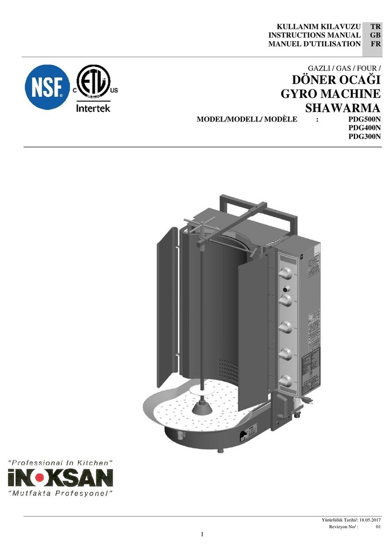
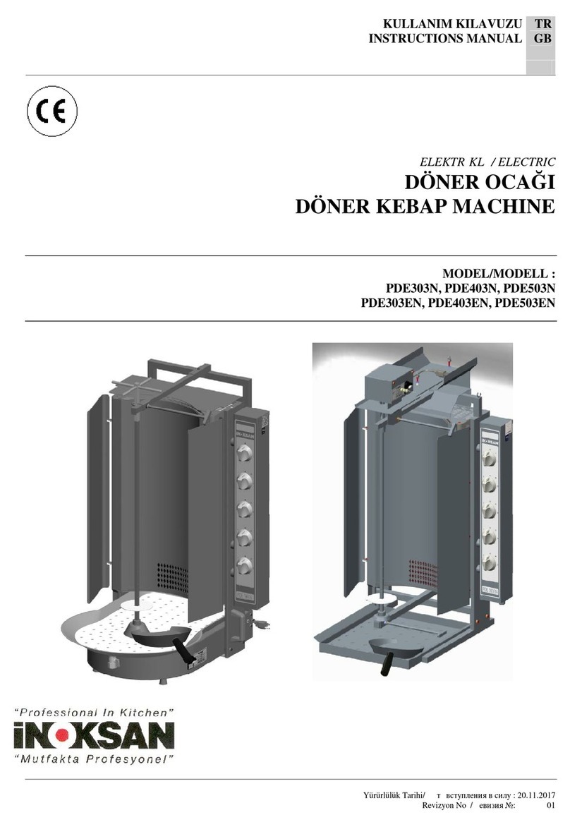
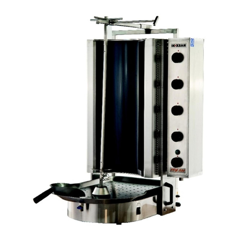
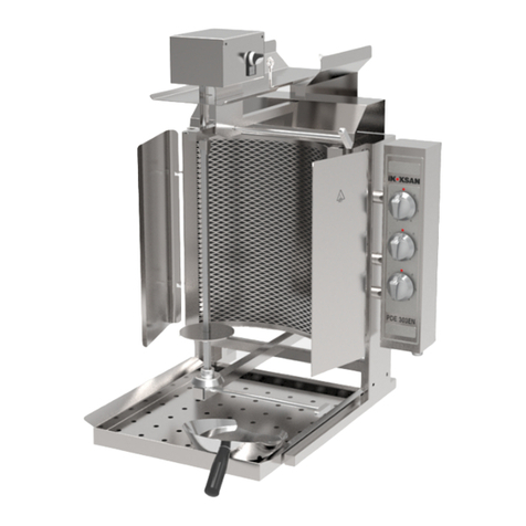
Inoksan PDG102MN User manual

1
KULLANIM KILAVUZU
INSTRUCTIONS MANUAL
MANUEL D'UTILISATION
TR
GB
FR
GAZLI / GAS / FOUR /
DÖNER OCAĞI
GYRO MACHINE
SHAWARMA
MODEL/MODELL/ MODÈLE : PDG102MN
PDG103MN
PDG104MN
PDG112MN
PDG113MN
PDG114MN
PDG 102 N
PDG 103 N
PDG 104 N
Yürürlülük Tarihi/: 20.11.2017
Revizyon No/ : 01

2
UYARI: Bu cihaz yürürlükteki mevzuata uygun olarak kurulmalı ve
sadece iyi havalandırılan bir alanda kullanılmalıdır. Yükleme ve bu
cihazı kullanmadan önce talimatlarına bakın.
WARNING: This appliance shall be installed in accordance with
current regulations and used only in well-ventilated space. Refer to
instructions before installing and using this appliance.
ATTENTION:Cet appareil doit être installé selon la législation en
cours et doit être utilisé seulement dans un environnement bien aéré.
Avant le chargement et l'utilisation de cet appareil, veuillez consulter
les instructions.
UYARI: Yanlış montaj, ayarlama, değiştirme, hizmet veya bakım
maddi hasar, yaralanma veya ölüme neden olabilir. Kurmadan veya
bu ekipmanı servis önce kurulum, kullanım ve bakım talimatlarını
okuyun.
WARNING: Improper installation, adjustment, alteration, service
or maintenance can cause property damage, injury or death. Read
the installation, operating and maintenance instructions thoroughly
before installing or servicing this equipment.
ATTENTION : Le mauvais montage, le réglage, le changement, le
service ou l'entretien incorrects peuvent causer des dommages, des
blessures ou le décès. Avant le montage ou la mise en service de cet
équipement, veuillez lire les instructions de montage, d'utilisation et
d'entretien.
a. If you smell gas, call your local gas utility emergency
line immediately. Until the service team arrives:
i. Don’t use electrical appliances or switches that
can cause sparks.
ii. Don’t smoke or light matches
iii. Leave doors and windows as they are
iv. Go outside
a. Se vous sentez la gaz, appelez immediatement votre ligne
d’urgence de distribution de gaz local. Jusqu’á ce que
l’équipe de service arrive:
i. Ne pas utiliser les appareils ou les commutateurs
électriques qui peuvent provoquer des étincelles.
ii. Ne pas fumer ou matchs lumière.
iii. Les portes et les fenêtres de congé comme ils sont.
iv. Sors
a. Eğer gaz kokusu alırsanız, derhal ACİL GAZ servisini arayınız.
Servis Ekibi gelene kadar
i. Elektrik aletleri yada elektrikanahtarlarını kullanmayın.
ii. Sigara yada kibrit yakmayın.
iii. Kapı ve perncereleri oldukları gibi bırakın
iv . Dışarı çıkın
GÜVENLİĞİNİZ İÇİN: Cihazın içinde benzin veya diğer yanıcı gaz veya sıvı madde kullanmayın depolamayın.
FOR YOUR SAFETY: Do not store or use gasoline or other flammable vapors or liquids in the vicinity of this or any other appliance.
POUR VOTRE SÉCURITÉ :Veuillez ne pas utiliser ou stocker de carburant ou autre gaz ou substance liquide inflammable dans l'appareil.
UYARI: Cihazın elektrik devre şeması kontol panelinin içindedir.
WARNING: Electrical circuit diagram of the appliance is inside the control panel.
ATTENTION : Le schéma du circuit électrique de l'appareil se trouve à l'arrière du panneau de commande inférieur.
3
GÜVENLİK SEMBOLLERİ / SAFETY SYMBOL / SYMBOLES DE SÉCURİTÉ
These symbols are intended to alert the user to the presence of important operating and maintenance instructions
in the manual accompanying the appliance.
Ces symboles sont destinés à alerter l’utilisateur sur certaines instructions d’utilisation et de maintenance figurant
dans le manuel fourni avec l’appareil.
SERVİS VE BAKIM / MAINTENANCE AND REPAIRS /MAINTENANCE ET RÉPARATİON
Contact your local authorized service agent for service or required maintenance.
Contactez un technicien agréé pour toute réparation ou maintenance.
Please record the model number, serial number, voltage and purchase date in the area below and have it ready when
you call to ensure a faster service.
Veuillez reporter le numéro de modèle, le numéro de série, la tension nominale et la date d’achat de l’appareil dans les champs respectifs ci-
dessous. Apprêtez ces informations au moment de l’appel pour pouvoir être plus rapidement servi.
Model No.
N° de modèle.
Authorized Service Agent Listing / Liste des techniciens agrees
Reference the listing provided with the unit / Indiquez la liste fournie avec
l’appareil
Or / ou
for an updated listing go to / demandez une liste actualisée aux adresses
suivantes
Website / Site web: www.inoksanUSA.com
Service Help Desk / Bureau d’aide
Company /Société:
Telephone / Téléphone:
Fax / Fax:
E-mail / Courriel
Serial No.
N° de série.
Voltage
Tension
nominale
Purchase Date
Date d’achat
Website / Site web: www.inoksanUSA.com
Mailing Address
Adresse postale:
ÖNEMLİ / IMPORTANT / IMPORTANT
Inoksan USA Corp.
849 Newark Tpke. Ste. 102
Kearny, NJ 07032
Office: 201.467.8333 | Fax: 201.624.7444 |
Cell: 201.906.1181
www.inoksanUSA.com
Inoksan USA Corp.
849 Newark Tpke. Ste. 102
Kearny, NJ 07032
Office: 201.467.8333 | Fax: 201.624.7444 |
Cell: 201.906.1181

4
Cihazı çalıştırmadan önce tüm kağıt koruma ve ambalajların söküldüğünden emin olun. Bu cihaz sadece kapalı konumda
monte edilmelidir.
Be sure to remove all paper protection and packing material from unit prior to lighting.
This appliance should be installed in a non-combustible location only.
Avant le fonctionnement de l'appareil, veuillez à retirer les protections et les emballages. Cet appareil doit être monté
seulement dans son état éteint.
TÜM GAZ KURALLARI VE YÖNETMELİKLERİ
Cihazın kurulumu ULUSAL YAKIT GAZ KOD "CSA ANSI Z223.1/NFPA 54' E" uygundur.
KANADA'DA MONTAJ AKIM CAN / CGA-B149.1 DOĞALGAZ TESİSAT KODUNA UYGUN ŞEKİLDE
OLACAKTIR.
İlgili talimat temin edilemezse;
1) Cihaz basınç değerleri 1/2 psi (3,5 kPa) üzerinde ise gaz besleme borusunun cihazla bağlantısınız kesiniz.
2) Cihaz basınç değerleri 1/2 psi (3,5 kPa) eşit çıktı ise gaz besleme borusunu manuel olarak kapatınız ve gaz besleme boru
sistemini izole ediniz.
The installation of the Appliance must conform to the
NATIONAL FUEL GAS CODE "ANSI Z223.1 - LATEST EDITION" AND ALL LOCAL GAS COMPANY RULES AND
REGULATIONS.
IN CANADA INSTALLATION SHALL BE IN ACCORDANCE WITH THE CURRENT CAN/CGA-B149.1 NATURAL
GAS INSTALLATION CODE
National Fuel Gas Code, ANSI Z223.1/NFPA 54, or the Natural Gas and, CSA B149.1, as applicable, including:
1) The appliance and its individual shutoff valve must be disconnected from the gas supply piping system during any
pressure testing of that system at test pressures in excess of 1/2 psi (3.5 kPa).
2) The appliance must be isolated from the gas supply piping system by closing its individual manual shutoff valve
during any pressure testing of the gas supply piping system at test pressures equal to or less than 1/2 psi (3.5 kPa).
TOUTES LES RÈGLES ET LES INSTRUCTIONS SUR LE GAZ
Le montage de l'appareil est conforme avec le code de gaz de carburant national « CSA ANSI Z223.1/NFPA 54' E ».
LE MONTAGE AU CANADA SERA EFFECTUÉ SELON LE FLUX / LE CODE D'INSTALLATION DU GAZ
NATUREL CGA-B149.1 ET
LE CODE D’INSTALLATION DU PROPANE CAN / CGA-B149.2.
Si les instructions en question ne sont pas fournies ;
1) Si les valeurs de la pression de l'appareil sont supérieures à ½ psi (3,5 kPa), coupez la conduite entre le tuyau
d'alimentation à gaz et l'appareil.
2) Si les valeurs de la pression de l'appareil sont égales à ½ psi (3,5 kPa) veuillez fermer le tuyau d'alimentation à gaz
manuellement et isolez le système du tuyau d'alimentation à gaz.
UYARI :Cihaz eğitilmiş personel tarafından kullanılmalıdır.
WARNING: Appliance must be used by trained personnel.
ATTENTION :L'appareil doit être utilisé par un personnel formé.

5
G - Gaz Girişi/Gas Inlet/Entrée de gaz
SPECIFICATIONS
Model
No
Width
(cm)
Depth
(cm)
Height
(cm)
Voltage
Gas
Type
Total Input
BTU’s
KW
Total
Amps
PlugType
Aproximate Weight
Shipping
Installed
PDG 102N - PDG 103N - PDG 104N
SPECIFICATIONS
Model
No
Width
(cm)
Depth
(cm)
Heigh
t
(cm)
Voltag
e
Gas
Type
Total
Input
BTU’s
KW
Total
Amps
PlugType
Aproximate
Weight
Shippin
g
Installe
d
VBE30
16.08”
24.97
”
32”
208V
-
-
4.5
21.6
NEMA6-30P
60
70
230V
-
-
4.2
18.2
240V
-
-
4.5
18.8
NEMA6-30P
VBG30
(40.79
)
(63.4
2)
(81.28
)
120V
NAT
30,000
-
0.4
NEMA5-15P
LP
-
0.4

6
PDG 102MN - PDG 103MN - PDG 104MN
SPECIFICATIONS
Model
No
Width
(cm)
Depth
(cm)
Heigh
t
(cm)
Voltag
e
Gas
Type
Total
Input
BTU’s
KW
Total
Amps
PlugType
Aproximate
Weight
Shippin
g
Installe
d
VBE30
16.08”
24.97
”
32”
208V
-
-
4.5
21.6
NEMA6-30P
60
70
230V
-
-
4.2
18.2
240V
-
-
4.5
18.8
NEMA6-30P
VBG30
(40.79
)
(63.4
2)
(81.28
)
120V
NAT
30,000
-
0.4
NEMA5-15P
LP
-
0.4

7
G - Gaz Girişi/Gas Inlet/Entrée de gaz
C
SPECIFICATIONS
Model
No
Width
(cm)
Depth
(cm)
Height
(cm)
Voltage
Gas
Type
Total Input
BTU’s
KW
Total
Amps
PlugType
Aproximate Weight
Shipping
Installed
VBE30
16.08”
24.97”
32”
208V
-
-
4.5
21.6
NEMA6-30P
60
70
230V
-
-
4.2
18.2
240V
-
-
4.5
18.8
NEMA6-30P
VBG30
(40.79)
(63.42)
(81.28)
120V
NAT
30,000
-
0.4
NEMA5-15P
LP
-
0.4
G - Gaz Girişi/Gas Inlet/Entrée de gaz
SPECIFICATIONS
PDG 112MN - PDG 113MN - PDG 114MN
SPECIFICATIONS
Model
No
Width
(cm)
Depth
(cm)
Heigh
t
(cm)
Voltag
e
Gas
Type
Total
Input
BTU’s
KW
Total
Amps
PlugType
Aproximate
Weight
Shippin
g
Installe
d
VBE30
16.08”
24.97
”
32”
208V
-
-
4.5
21.6
NEMA6-30P
60
70
230V
-
-
4.2
18.2
240V
-
-
4.5
18.8
NEMA6-30P
VBG30
(40.79
)
(63.4
2)
(81.28
)
120V
NAT
30,000
-
0.4
NEMA5-15P
LP
-
0.4

8
SPECIFICATIONS
ModelNo
Width (A)
Depth (B)
Height
(C)
Voltage
GasType
Total
Input
BTU’s
KW
Total
Amps(max.)
Plug Type
Aproximate Weight
Shipping
Kg/Lb
Installed
Kg/Lb
PDG
102MN
530mm
20,86"
769mm
30,27"
910 mm
35,82”
115V
NG
20.428
5
0.4
NEMA 5-15P
31/68,20
40/88
PDG
103MN
530mm
20,86"
769mm
30,27"
973mm
38,3”
115V
NG
30.717
7,5
0.4
NEMA 5-15P
33,8/74,36
42,8/94,16
PDG
104MN
530mm
20,86"
769mm
30,27"
1148mm
45,20”
115V
NG
40.956
10
0.4
NEMA 5-15P
37,8/83,16
46,8/102,96
PDG
112MN
530mm
20,86"
769mm
30,27"
843mm
33,19”
115V
NG
20.428
5
0.4
NEMA 5-15P
31/68,20
40/88
PDG
113MN
530mm
20,86"
769mm
30,27"
919mm
36,18”
115V
NG
30.717
7,5
0.4
NEMA 5-15P
33,8/74,36
42,8/94,16
PDG
114MN
530mm
20,86"
769mm
30,27"
1089mm
42,87”
115V
NG
40.956
10
0.4
NEMA 5-15P
37,8/83,16
46,8/102,96
PDG
102N
530mm
20,86"
769mm
30,27"
823mm
12,71”
115V
NG
17.060
5
0.4
NEMA 5-15P
26/57,2
35/77
PDG
103N
530mm
20,86"
769mm
30,27"
893mm
35,15”
115V
NG
25.591
7,5
0.4
NEMA 5-15P
28,8/63,36
37,8/83,16
PDG
104N
530mm
20,86"
769mm
30,27"
1062mm
41,81”
115V
NG
34.121
10
0.4
NEMA 5-15P
32,8/72,16
41,8/91,96
T1
Ülke / Country / Pays
Gaz / Gas /
Gaz
Basınç
Pressure
Mbar
"WC
Enjektör / İnjector / Injecteur
mm
İnch / pouce
ABD / US / États-Unis
NG
G20
15
6"
1,55
0,061"
LG
G30
27
10.5”
0,93
0,037”
YERİNE MONTAJI / INSTALLATION ON SITE /MONTAGE SUR PLACE
Cihazın montajını Davlumbaz altına yapmanız önerilir.
Cihazın düzgün çalışması için ve gerektiğinde acil müdehale edebilmek ve yanma odsaının performansına yeterli
boşluk sağlanması için uygun montaj boşluklarını veriniz.
We recommend you to install the appliance under the Hood.
Provide proper installation gaps to allow adequate clearance for the performance of combustion chamber and to ensure that the
appliance correctly and to intervene in case of an emergency.
Il est conseillé d'effectuer le montage de l'appareil sous la hotte.
Pour le bon fonctionnement de l'appareil et afin de pouvoir intervenir dans l'urgence et pour fournir un espace suffisant à la
performance de la chambre de chauffage, des espaces de montage convenables sont nécessaires.
UYARI : Cihazın yakınlarında yanıcı madde bulunudurmayınız. Cihazın bulunduğu yeri temiz tutunuz.
Cihazın yanma performansının iyi olması için, hava akışını engellemeyin.
WARNING: Thisappilance is can only be installed on non combustible floor. Do not keep flammable material beside
the appliance. Keep the appliance free and clear front combustibles.
Do not block air flow of cumbustion and ventilation air to ensure a good burning performance.
Do not obstruct the flow of cumbustion and ventilation air.

9
ATTENT1ION : Veuillez ne pas laisser de substance inflammable près de l'appareil. Veillez à ce que l'endroit où se trouve l'appareil
soit propre.
Pour une bonne performance de l'appareil, veuillez ne pas créer d'obstacle au flux d'air.
Ne pas obstruer le flux de combustion et de ventilation.
UYARI : Cihazın temizliği ve bakımı esnasında fişi pirizden çekiniz.
WARNING: Unplug the appliance during cleaning and maintenance.
ATTENTION :Lors du nettoyage et de l'entretien de l'appareil, veuillez retirer la fiche de la prise.
BOŞLUKLAR / CLEARANCES/ ESPACES
Yanıcı
Combustible
Materials
Incombustible
Materials
Yanmaz
Non-Combustible
Materials
Incombustible
Materials
Zemin / Floor /
Plancher
N/A
1” / 25.4 mm
Yanlar / Sides/Côtés
N/A
12” / 304.8 mm
Arka / Back/Arrière
N/A
3” / 76.2 mm
GAZ TESİSATI / GAS INSTALLATION / INSTALLATION DE GAZ

10
TR
Motor Bağlantısı – PDG 102MN-102N-103MN-103N-104MN-104N

11
Motor Bağlantısı – PDG 112MN-113MN-114MN

12
Cihazı kullanmaya başlamadan
önce kullanım kılavuzunu
mutlaka okuyunuz ve ihtiyaç
duyduğunuzda başvurmak üzere
saklayınız.
Üretici firma; kullanım kılavuzuna
uymadan yapılan herhangi bir
işlemden, yetkili teknisyenler
tarafından yapılmayan bakım veya teknik
müdahalelerden dolayı insanlara veya
eşyalara karşı meydana gelen nihai
zararlardan sorumluluk kabul etmez.
1. MONTAJ
Cihazın montajı, gaz bağlantısı ve farklı
gazlara çevrimi, elektrik tesisatı yöresel
standartlara göre uzman kişiler tarafından
"Teknik Özellikler" tabloları baz alınarak
yapılmalıdır.
Cihazı uygun bir tezgah üzerine teraziye
alarak yerleştiriniz.
Cihazı, çıkan duman ve kokunun dışarı
atılabilmesi için davlumbaz altına veya
yeterli havalandırmanın yapılabildiği bir
ortama yerleştiriniz.
Cihazın, mutfak mobilyalarının dekoratif
kaplamaların vs. hemen yakınına monte
edilmesi durumunda, bunların yanmaz
malzemeden imal edilmiş olması tavsiye
edilir; aksi durumda bunlar, yanmaz, ısı
izolasyonlu malzeme ile kaplanmalıdır ve
yangından korunma talimatlarına özenli
bir şekilde riayet edilmelidir.
2. KULLANICI TALİMATI
Cihaza çizelgede belirtilen et
kapasitesinin dışında aşırı yükleme
yapmayınız.
Radyanların kumandası yatay veya
düşey sıralar halinde ayrı ayrı
yapılabilmekte olup, döner etinin
büyüklüğüne göre radyanları
devreye alınız.
Üst gövde 1d/d’lık motor, şişi eğik
yada dik konumda döndürmekte,
homojen pişirme ve ergonomik
kullanım kolaylığı sağlamaktadır.
Kullanıcı çalışma sırasında “aşçı
şapkası ve eldiveni “ kullanmaya
özen göstermelidir.
UYARI : Yeterli havalandırma için cihazın etrafında yeterli
alan bırakın. Ünitedeki tüm etiketleri okuyunuz ve
uygulayınız.
GAZ BASINCI ÖLÇME
Gaz bağlantısı yapıldıktan sonra gaz giriş basıncının tabloda verilen
değerlere uygun olması gerekir. Bunun için uygun debi ve basınç
sağlayacak dedantör kullanılmalıdır.
Cihazınızın kullanacağınız gaza göre adaptasyonunun yapılıp
yapılmadığından emin olunuz. Eğer uygun değil ise enjektör değişikliği
yapılması gerekir.
Montaj için gerekli tüm parçalar imalatçı firma tarafından sağlanacaktır.
Basınç ölçümü yapabilmek için öncelikle gaz vanasını kapatınız.
Aşağıdaki aşamaları sırasıyla yapınız.

13
4. ÇALIŞTIRMA
Her gaz musluğu yatay ve/veya sıralanmış 1
ad. radyanı kontrol eder.
Önce ana gaz valfini açıp, pilotu
manuel yakınız, ardından en alttan
başlayarak brülörleri yakınız
İlk yakma işlemi için (alt brülör) "1" nolu
düğmeye basıp "0" konumundan saat dönüş
yönü tersinde çevirerek tam alev konumuna
getiriniz. Kısık alev için düğmeyi saat
yönünün tersine yarım alev işaretine kadar
çevirmeye devam ediniz.
Şişi döndürmek için cihaz fişini bir prize takınız ve
"2" nolu "I-0-II" konumlu anahtarı “I” veya “II”
konumuna (Sağ/Sol dönüş) getiriniz.
5. CİHAZI KAPATMAK
Cihazı kapatmak için ; en alttan başlayarak düğmeleri
tek tek saat yönünde sıfır konumuna gelene kadar
çeviriniz. Motor güç şalterini "O" konumuna getir.
“Tüm brülörleri kapattıktan sonra, ana gaz
valfini kapatıp gazı tamamen kesiniz “
“Cihazı kapattıktan sonra, tekrar açmadan önce
5 dakika bekleyiniz.”
6. EMNİYET TEDBİRLERİ
Cihazı gözetim/kontrol dışı kullanmayınız.
Çalışma bölgesini terk ettiğinizde cihazı daima
kapatınız.
Maddelerine zarar vermeyecek bir dezenfektan
ile temizleyiniz.
Su ile iyice durulayın ve başka bir kağıt havlu
yada yumuşak kumaşla kurutun.
7. ELEKTRİK GİRİŞİ
Cihaz 115V AC 60Hz şebeke gerilimiyle
beslenmelidir.
Cihaz mutlaka topraklı prize bağlanmalıdır.
TOPRAKLAMA
UYARI: Bu cihaz elektrik çarpmalarını
engellemek amacıyla topraklı fiş ile
donatılmıştır. Fiş topraklı pirize
takılmalıdır. Toprak bağlantısı asla kesilmemeli
ve/veya toprak bağlantısı değiştirilmemelidir.
0
KAPALI /
BRÜLÖR TAM ALEV
BRÜLÖR KISIK ALEV
Cihazı kullanmaya
başlamadan önce kullanım
kılavuzunu mutlaka
okuyunuz ve ihtiyaç duyduğunuzda
başvurmak üzere saklayınız.
Üretici firma; kullanım
kılavuzuna uymadan yapılan
herhangi bir işlemden, yetkili
teknisyenler tarafından yapılmayan
bakım veya teknik müdahalelerden
dolayı insanlara veya eşyalara karşı
meydana gelen nihai zararlardan
sorumluluk kabul etmez.
3. MONTAJ
Cihazın montajı, gaz bağlantısı ve
farklı gazlara çevrimi, elektrik tesisatı
yöresel standartlara göre uzman kişiler
tarafından "Teknik Özellikler" tabloları
baz alınarak yapılmalıdır.
Cihazı uygun bir tezgah üzerine
teraziye alarak yerleştiriniz.
Cihazı, çıkan duman ve kokunun dışarı
atılabilmesi için davlumbaz altına veya
yeterli havalandırmanın yapılabildiği
bir ortama yerleştiriniz.
Cihazın, mutfak mobilyalarının
dekoratif kaplamaların vs. hemen
yakınına monte edilmesi durumunda,
bunların yanmaz malzemeden imal
edilmiş olması tavsiye edilir; aksi
durumda bunlar, yanmaz, ısı
izolasyonlu malzeme ile kaplanmalıdır
ve yangından korunma talimatlarına
özenli bir şekilde riayet edilmelidir.
4. KULLANICI
TALİMATI
Cihaza çizelgede belirtilen et
kapasitesinin dışında aşırı
yükleme yapmayınız.
Radyanların kumandası yatay
veya düşey sıralar halinde ayrı
ayrı yapılabilmekte olup, döner
etinin büyüklüğüne göre
radyanları devreye alınız.
Üst gövde 1d/d’lık motor, şişi
eğik yada dik konumda
döndürmekte, homojen pişirme
ve ergonomik kullanım kolaylığı
sağlamaktadır.
Kullanıcı çalışma sırasında “aşçı
şapkası ve eldiveni “ kullanmaya
özen göstermelidir.
UYARI : Yeterli havalandırma için cihazın etrafında yeterli
alan bırakın. Ünitedeki tüm etiketleri okuyunuz ve
uygulayınız.
GAZ BASINCI ÖLÇME
Gaz bağlantısı yapıldıktan sonra gaz giriş basıncının tabloda verilen
değerlere uygun olması gerekir. Bunun için uygun debi ve basınç
sağlayacak dedantör kullanılmalıdır.
Cihazınızın kullanacağınız gaza göre adaptasyonunun yapılıp
yapılmadığından emin olunuz. Eğer uygun değil ise enjektör
değişikliği yapılması gerekir.
Montaj için gerekli tüm parçalar imalatçı firma tarafından
sağlanacaktır.
Basınç ölçümü yapabilmek için öncelikle gaz vanasını kapatınız.
Aşağıdaki aşamaları sırasıyla yapınız.

14
Bu cihaz, monte edildiğinde, yerel düzenlemelere
uygun olarak veya Ulusal Kodlar, ANSI / NFPA
70 veya Kanada Elektrik Yasası CSA ile yerel
kodlara göre topraklanmalıdır.
C22.2, uygulanabilir olduğu gibi. "
UYARI : Cihazı direkt yada yüksek basınçlı
su ile temizlemeyiniz. Aksi takdirde elektrik
tesisatı arızasına neden olabilirsiniz.
8. BAKIM & TEMİZLİK
Bakım yada temizlik faaliyetine başlamadan
önce cihazın elektrik bağlantısını mutlaka
kesiniz.
Cihaz ilk kullanımdan önce, elektrik
bağlantısı kesilmeli ve ılık sabunlu su ile
temizlenmelidir.
Cihaz üzerine kesinlikle su sıkılmamalı veya
dökülmemelidir.
Cihazı her çalışma günü sonunda ılık sabunlu
suya bastırılmış bir bez ve gıda maddelerine
zarar vermeyecek bir dezenfektan ile
(özellikle etin temas ettiği yerleri)
temizleyiniz.
Etin temas ettiği şiş ve tepsi sacları bulaşık
makinesinde yıkanabilir.
Cihaz yüzeyi temizlenirken aşındırıcı içeriği
olan deterjanlar, tel fırçalar vb. yüzeylerde
çizik yapabilecek malzemeler kullanmayınız.
Eğer cihaz uzun müddet kullanılmayacaksa,
yüzeyler ince bir tabaka vazelinle
kaplanmalıdır.
Cihazda tehlikeli bir durum görülmesi
halinde yetkili servise haber veriniz.
Ehliyetsiz kişilerin cihaza müdahale etmesine
izin vermeyiniz.
Cihazınızın bakım zamanı geldiğinde ve/veya arıza
yaptığında üretici firma ile irtibata geçiniz.
9. FARKLI GAZ TİPLERİNE DÖNÜŞÜM
Farklı gazlara adaptasyon için "T1” tablosuna bakınız.
“T1” tablosundan kullanılacak gaz tipine ve basıncına uygun enjektörü
seçiniz ve sökülen enjektörün yerine takınız.
Cihazınızı üreticinin ayarladığı gaz tipinden farklı bir gaz tipine adapte
ettikten sonra mevcut etiketin sökülerek yeni gaz tipine göre yazılmış etiketin
yapıştırılması gerekir.
9.1 Enjektörün Değiştirilmesi/ Replacement of Injector
Uygun enjektörü T1 tablosundan seçiniz.
Cihazın arka sacını çıkarınız.
(1). Radyanı karşınıza alınız. (2). Radyanın üzerinde bulunana firketeyi
çıkarınız. (3)Enjektörü radyandan çıkarınız. (4). Yeni enjektör ile
değiştiriniz. ve yeni enjektörü aynı yerine takınız. (5).Firketeyi çıkardığınız
şekilde takınız. (6) Gaz tipi dönüştürme işlemi tamamlanmıştır.
Enjektör çapları enjektör üzerinde yazılıdır.

16
GB
Motor Connection PDG 102MN-102N-103MN-103N-104MN-104N
tion PDG 102MN-102N-103MN-103N-104MN-104N

17
Motor Connection PDG PDG 112MN-113MN-114MN
Place complete skewers the number "1" in
the slot first. Attach the other side of the
upper part of the skewer.
Mount the hairpin number
"2" on the skewer number
"1". Pass mirror number "3"
right up down up to the
hairpin.
Assemble profile "1" by passing into
profile "A". "Pass profile "1" through
profile "2", assemble the number "3" with
the apparatus.

18
Always read the instruction manual
before starting to use the appliance and
keep it for future reference when you
need it.
Manufacturer company does not accept any
responsibility for any operations performed
without following the instruction manual,
and for damages occurred against people or property
due to maintenance or technical interventions by
qualified technicians.
1. INSTALLATION
Technical Specifications" table should be based
on when installation of the appliance, gas
connection and conversion to different gases,
electricity supplies are installed by experts in
accordance with local standards.
Place the appliance on a bench by taking it on a
scale.
Place the appliance under a fume hood or in an
environment where adequate ventilation can be
carried out in order to exhaust fumes and odors.
2. USER INSTRUCTION
WARNING: Allow enough space around the
unit for adequate ventilation. Read all labels
on the unit and follow their instructions.
If the appliance is mounted in the immediate vicinity of
kitchen furniture, decorative coating etc., it is
recommended that they should be made of non-
combustible material; otherwise they must be coated with
non-burning thermal insulation material and fire protection
instructions must be followed carefully.
3. GAS PRESSURE
PEASUREMENT
"Toques and mittens" should be used while
user working.
Gas inlet pressure must be in accordance with the
values given in the table after the gas connection.
For this purpose, a hood must be used to ensure
proper flow rate and pressure.
Make sure the adaptation of the appliance is
carried out in accordance with the gas you will e.
If it is not appropriate, the injector must be
changed.
All the necessary components for installation will
be provided by the manufacturer.
Do not overload the appliance more then the
specified meat capacity in the chart
Controlling of the radians can be performed separately in
horizontal or vertical row, put the radians into use in
accordance with the size of the doner meat.
1d/d motor placed in the lower body rotates the
skewer in an inclined or upright position, providing
ease of homogeneous cooking and ergonomic use.

19
LIGHTING INSTRUCTION
•Each gas tap controls a horizontal and / or a
rowed of radios.
•First open the main gas valve,
manually burn the pilot, then burn
the burners starting from the bottom
• For the first burning operation (lower
burner), push button "1" and turn counter
clockwise from "0" to full flame position.
• For the half flame, press the button and
turn counter clockwise from "0" to the
half flame position.
• For burn the other burners, turn the burners
buttons clockwise from "0" position to full
flame position, from the lower hold down the
flame until the flame is jumped, and leave the
combustion process
directly or with high-pressure water. Otherwise you
may cause an electrical installation malfunction.
To rotate the skewer, plug the appliance plug "1" into a socket
and bring the key "2" with position "I-0-II" to the postion "I" or
"II" (Right/Left rotation).
SHUTDOWN INSTRUCTION
To shutdown the appliance, turn all knobs clockwise one by
one until they are at position 0 starting with the bottom knob.
Bring motor power switch to “0”.
After all the burners have been switched off, close the
main gas valve and completely cut off the gas
“Wait for 5 minutes before restarting the appliance
when you turn it off.”
SAFETY PRECAUTIONS
When the surfaces of the robax glass and storage
system cools down, use a few drops of suitable cleaner
and wipe clean with a soft cloth or paper towel.
Rinse thoroughly with water and dry with another
paper towel or soft cloth.
4. POWER INLET
The appliance must be supplied with 110V AC 60Hz
mains voltage.
The appliance must be grounded.
GROUNDING
WARNING : The appliance is equipped with a
three-prong (grounding) plug for your against
shock hazard and should be plugged directly into a
properly grounded three-prong receptacle. Do not cut or remove
the grounding prong from this plug .
The appliance, when installed, must be electrically grounded
in accordance with local codes, or in the absence of local
codes, with the National Electrical Code, ANSI/NFPA 70,
or the Canadian Electrical Code, CSA C22.2
0
CLOSED
BURNER FULL FLAME
LEFT BURNER HALF FLAME

20
5. MAINTENANCE
Disconnect the electrical connection of the
appliance immediately before beginning
maintenance or cleaning activities.
Before the first use, the electrical connection of the
appliance must be disconnected and it must be
cleaned with warm soapy water.
Water must definitely not be sprayed or spilled on
the appliance.
Clean the appliance at the end of each working day
with a piece of cloth soaked with warm soapy water
and with a disinfectant that will not harm nutrition
products (especially the areas in contact with
meat).
Pins and tray plate contacted by the meat may be
washed in the dishwasher.
Do not use materials that can scratch the surface
such as detergent with abrasive ingredients, wire
brushes, etc. when cleaning the surface of the
appliance.
If the appliance will not be used for a long period
of time, the surface should be coated with a thin
layer of Vaseline.
Notify the authorized service if the appliance is
considered in a dangerous situation. Do not allow
incompetent persons to interfere with the
appliance.
Contact manufacturer when the maintenance
period of the appliance has expired and/or when
the appliance has a fault.
WARNING: Do not clean the appliance with
9. TRANSFORMATION FOR DIFFERENT
GAS TYPES
Refer to table “T1” for adaptation to different gas
types.
Choose the injector suitable for the gas type and pressure
to be used from table “T1” and install it to the housing of
the removed injector.
Label for the new gas type shall be affixed by removingthe
current label after adapting the appliance to a different gas
type than the gas type set by the manufacturer.
9.1 Replacement of Injector
Select suitable injector from table T1.
Remove the rear plate of the appliance.
(1) Face the radiant. (2) Remove the pin on the
radiant. (3) Remove injector from the radiant. (4)
Replace with new injector and install the new
injector to the same housing. (5) Install the pin as
you have removed it. (6) Gas type transformation is
complete.
Injector diameters are printed on the injectors.

21
FR
Motor Connection PDG 102MN-102N-103MN-103N-104MN-104N
ATTENTION: La partie de
silicium du câble ne doivent pas
passer par la spirale de
l'interrupteur. Elle doit être
passée par la spirale de transition
ayant la partie fine du câble.
Faitez le montage de la pièce tôlée du moteur
complet numérotée “2” sur le profil
numéroté “3” à l’aide de bras de grillade
numéroté “1”.
L’épingle numérotée “2” est
monté sur la broche à rôtir
numérotée “1”. Faites glisser le
miroir numéroté “3” de haut en
bas.
Placez d'abord la broche au nid
numéroté "1" et puis assurez-vous que
la broche est attachée à la partie
supérieure de l'autre extrémité.
This manual suits for next models
8
Table of contents
Languages:
Other Inoksan Commercial Food Equipment manuals

Inoksan
Inoksan PDG102 User manual

Inoksan
Inoksan KSN 115 User manual

Inoksan
Inoksan PERFECT 700 Series User manual

Inoksan
Inoksan PDE403N User manual

Inoksan
Inoksan 700 Series User manual

Inoksan
Inoksan 700 Series User manual

Inoksan
Inoksan inosmart FBG10T User manual

Inoksan
Inoksan PDG300 User manual

Inoksan
Inoksan INO-SBF146 User manual

Inoksan
Inoksan FKE006 User manual