Safety Information and Precautions
- 2 -
Disclaimer
•The drawings in the manual are shown for description only and may not
match the product you purchased.
•The instructions are subject to change, without notice, due to product or
software upgrade, specication modication as well as efforts to increase the
accuracy and convenience of the manual.
•Contact our agents or customer service center if you have problems during
the use.
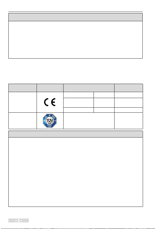
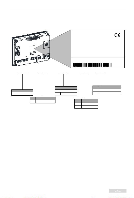
Approvals
Certification marks on the product nameplate indicate compliance with the
corresponding certicates and standards.
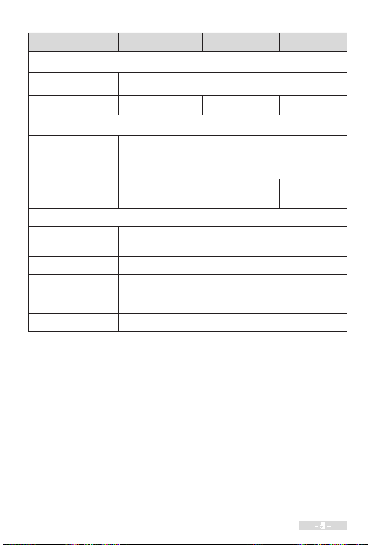
Certication Mark Directives Standard
CE
EMC directives 2014/30/EU EN61131-2
LVD directives 2014/35/EU EN 61010-1,
EN61010-2-201
RoHS directives 2011/65/EU EN 50581
TUV - EN 61010-1,
EN61010-2-201
Note
•The above EMC directives are complied with only when the EMC electric
installation requirements are strictly observed.
•Machines and devices used in combination with this drive must also be CE
certified and marked. The integrator who integrates the drive with the CE
mark into other devices has the responsibility of ensuring compliance with CE
standards and verifying that conditions meet European standards.
•The installer of the drive is responsible for complying with all relevant
regulations for wiring, circuit fuse protection, earthing, accident prevention
and electromagnetic (EMC regulations). In particular fault discrimination
for preventing re risk and solid earthing practices must be adhered to for
electrical safety (also for good EMC practice).
•For more information on certification, consult our distributor or sales
representative.