© Copyright 2014 InPower LLC
ETM40B/C Owner’s Manual
2
Document: OM-03 Version Code: H
Date: Oct 15, 2009 Date: Oct 27, 2014
Operation
When the vehicle is parked and Chassis Ready Conditions are satisfied, the
engine idle speed may be controlled by selection of one of the five available
modes: three presets, charge protect or variable RPM. The preset RPM
modes may be adjusted via three calibration potentiometers on the top of the
ETM40 unit.
Chassis Ready Conditions
1. Parking brake is set
2. For automatic transmission: gear shift lever is in PARK
3. For manual transmission: foot is off the clutch pedal
4. Foot is off the service brake
5. Foot is off accelerator pedal
6. Vehicle is stationary
7. Engine is started and idling
Modes of Operation
A.Three Preset RPM High Idle Modes:
Function: Increase Idle to a preset RPM value
Terminals: RPM1, RPM2, RPM3
Activation: Apply ground to terminal
Range of Calibration: 1200 to 2600 RPM
Type of Adjustment: Internal potentiometers
RPM1 Adjustment: Potentiometer 1
RPM2 Adjustment: Potentiometer 2
RPM3 Adjustment: Potentiometer 3
B.Charge Protect Mode:
Function: Varies RPM to maintain 14 volts at battery
Terminal: CHRG
Activation: Apply ground to terminal
RPM Range: 1200 to 2600 RPM
C.Variable RPM Mode:
Function: Varies RPM as a function of voltage on VRPM
Terminal: VRPM
Adjustment: 10k Ohm Potentiometer between terminal and ground
Enable: Turn potentiometer down to zero resistance, then
slowly increase until reaching desired RPM
Disengage: Turn Potentiometer down to zero and RPM will drop to
standard idle
RPM Range: 1200 to 2600 RPM
D.Mode Priorities:
RPM1 Highest - will override all other modes
RPM2 Second - will override lower modes
RPM3 Third - will override lower modes
Variable RPM Lowest - will only activate when all other modes are off
© Copyright 2014 InPower LLC
ETM40B/C Owner’s Manual
3
Document: OM-03 Version Code: H
Date: Oct 15, 2009 Date: Oct 27, 2014
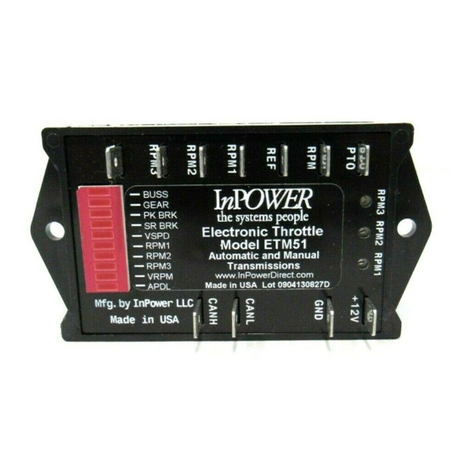
Status Indicators
A five segment LED provides status and problem detection information. Refer
to the following table for coding of these functions.
LED Status Indication
ON/OFF On Solid Module ON & Functioning
Flashing Module ON, problem detected
GEAR On Solid Gear = Park, Park Brk set, Servics Brk off
Flashing Problem detected
RPM1 On Solid RPM1 terminal grounded, engine at RPM1
Flashing RPM1 terminal grounded, engine at low idle
RPM2 On Solid RPM2 terminal grounded, engine at RPM2
Flashing RPM2 terminal grounded, engine at low idle
RPM3 On Solid RPM3 terminal grounded, engine at RPM3
Flashing RPM3 terminal grounded, engine at low idle
RPM2/
RPM3 On Solid VRPM terminal grounded, engine at high idle
Flashing VRPM terminal grounded, engine at low idle
NOTE: The GEAR diagnostic LED on the 6.0 L engine applications should not be used
as it will contain erroneous indications.
Specifications
Electrical
Input Voltage (+12V Terminal): 8 to 16 V
Input Current (+12V Terminal): 37mA
Standby Current: 28mA
Input Current (on/off terminal): 1mA
Control Current: 1mA
Mechanical
Weight: 0.17lbs
Connections: Faston 0.25 inch terminals
Case Material: Cyolac thermoplastic (UL 94VO)
Encapsulation Material: Epoxy potting compound, resistant to most fuels, oils,
acids and cleaning agents.
Installation
The ETM40 module should be mounted inside the cab, under the dashboard.
A supplied five foot cable connects to the Ford wiring harness’ four pin
connector. The mode activation connections must be supplied by the user to
connnect to the 0.25 Faston terminals. (See wiring diagram.)
Note: Excursion chassis do not have an APCM harness connector for the
ETM40 data cable. Aspecial data cable must be used that will connect to the
vehicle’s OBD-II Data Link Connector. Contact InPower, LLC for details.
Setup and Calibration
The only calibration required is to select each of the three preset modes
(RPM1, RPM2 and RPM3) and adjust the three respective potentiometers on
the ETM40 to the desired RPM.
