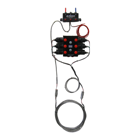
TRAUSCH DYNAMICS PoppetPLUS 2 User manual

Installation Guide
PoppetPLUS 2 Valve Kit - 15 GPM Part # 9502732
Warning
To avoid serious injury or death:
•Park the equipment on level ground, apply the parking brake, disengage running equipment, lower all implements to the
ground, shut o the engine and remove the key.
• Read and comprehend the tractor and implement or attachment owner’s manual before installing or operating this valve.
• Always wear safety glasses and proper personal protection equipment before and during installation of this valve.
• Pressurized hydraulic uid can cause serious injury. The forces created can penetrate skin. Relieve all system pressure
before disconnecting lines. Be sure that the equipment is in a “zero-energy” state. Before applying pressure and ow to
this valve, be sure that all connections are tight and the hydraulic hoses are not damaged in any way. Hydraulic uid can
leak from pin-holes and cause injury. Visually inspect all connections and never use your hands or ngers to inspect for
leaks. If you are injured by injection of hydraulic uid, see a doctor. Failure to do so may cause serious injury or death.
Parts List
Part Qty. Description Order #
A 1 Manifold 7068108
B 4 Valve, 2P2W, Poppet 7010128
C 4 Solenoid 7013763
D 4 Solenoid Nut 7013770
E 1 Fuse Kit 9502615
F 1 Solenoid Wire Harness 9502740
G 1 20’ Extension Wire Harness 9502741
H 1 Switch Box/Wire Assembly 9502746
I 2 Toggle Switch 5056117
J 2 Toggle Boot 5056118
K 2 Indicator Light 5056138
Document # 8889014
Power Source
+-
D
B
C
A
E
9502615
Fuse Kit
F
G
H
I
J
K

Step 1 - Valve Mounting
Note: Ports in the valve are #8 SAE o-ring. DO NOT use Teon tape, rector seal, liquid anaerobic, pipe dope etc. on the threads.
NO THREAD SEALANT IS REQUIRED. It is important to pre-lube the o-rings with hydraulic uid before installing the ttings into
the valve body. Valve mounting is unrestricted. Mount the valve in any position. Be sure that the tops of the solenoids does not
contact metal. The two mounting holes accept 3/8” bolts. The bolts should be at least 2-1/2” long to clear the manifold.
Step 2 - Electrical Installation
Disconnect the negative battery terminal before installing.
CAUTION: The valve should be mounted and connected to the wiring harness before the control switch is connected to the power
source. This will prevent accidental shorting of the control wires to ground.
Attach the red power wire to a keyed power source in your fuse-box. Make sure that the source of power is on only when the ma-
chine is in operation. This will prevent unwanted activation and possible battery drain. The black ground wire may be connected
to the equipment frame or engine block. Metal-to-metal contact is required for a good ground. Paint or powder-coating may
have to be removed to ensure a metal-to-metal ground.
If a fused 10-20 amp direct power source is not available on the equipment you are installing this valve control, use the included
fuse kit (9502615). Use this kit to adapt the power connection to the keyed equipment fuse block. Instructions are included with
the fuse kit. It is very important to fuse this valve control. Failure to fuse this valve control can cause damage and voids the war-
ranty.
Power Source
+-
GREEN
RED
GREEN
RED

Step 3 - Hydraulic Plumbing
Follow the plumbing schematic as illustrated. Hoses are not provided as hose lengths vary per application.
Operation
This poppet selector valve operates by energizing TWO solenoids when a toggle switch is activated.
The cylinder located on the ports labeled “1” will operate when the corresponding toggle switch is activated.
The cylinder located on the ports labeled “2” will operate when the corresponding toggle switch is activated.
Directional control is controlled by the existing tractor remote valve located in the cab. This valve does not control direction of
ow. The ow coming into “P1” or “P2” determines the direction of ow in the circuit.
CAUTION: Do not loosen or remove any ttings or the valve cartridge while there is pressure in the system or a load is being held
up by the valve.
Existing Tractor
Remote Valve

Maintenance
As with any piece of equipment, periodic maintenance will help provide longer life and trouble-free operation of your new
PoppetPLUS system. Periodically inspect those electrical connections which are exposed to the elements for signs of cor-
rosion or other damage. Replace any terminals that look as if they might fail in the eld. Inspect the cable connecting the
switch to the valve. Normal operation over time can cause a cable to move to a dangerous area. If the cable is in any danger
of being crushed or cut, move it to a safer area and secure it. Check the hydraulic hoses connected to the valve. Wipe the
body of the valve o and look for leaks. Tighten or replace any ttings you suspect of leaking. Inspect the hydraulic hoses for
signs of leaking, cracking or bulging. Replace any hoses that show signs of failure.
Troubleshooting
If the valve was previously working, the trouble is most likely the result of a blown fuse, damaged wiring or a bad switch. If this
is a new installation, carefully check the hydraulic connections to make sure that the valve is installed correctly as shown in the
diagram. Also, inspect hydraulic coupler tips for proper mating. Incompatible couplers will usually not allow the ball or poppet to
unseat properly and prevent a good hydraulic connection.
Electrical Troubleshooting
A simple way to determine if a solenoid is being energized is by touching the mounting nut on the valve coil with a screwdriver.
The coil is an electromagnetic part and will attract the screwdriver when the power is on. If the screwdriver does not stick to the
top of the coil, use a voltmeter to check for voltage between the coil terminal and the mounting nut. If the voltage is at least 11
volts, the valve should be functioning. When the coil is energized a click should be audible from the valve. The sound may be
quiet or mued if the valve is under pressure. If the voltage is low, check the voltage at the source where the power wire for the
control was connected. If no voltage is found, try measuring the voltage between the coil terminal and the tractor frame. If volt-
age is indicated, the valve is not being grounded. Check the black ground wire. If no voltage is indicated between the coil power
wire and the ground, rst check the fuse and then the red wire to the switch control box.
Hydraulic Troubleshooting
If none of the circuits work and the solenoid coils are being operated with at least 11 volts (measured at the coil), check that the
supply connections from the tractor remote to the valve are correct. Check that the cylinders are connected to the valve as shown
in the diagram. If necessary, remove the valve and connect the cylinder to the remote outlet to conrm that the supply hoses and
coupler tips are in working order.
Warning
To avoid serious injury or death:
• Use extreme care to make sure all individuals are safely clear from equipment and the nearby area whenever operating
remote valve control switches.
• Operating electrical controls (even when the remote lever is in neutral or the engine is stopped) will result in the valves
operating and may result in equipment moving suddenly without warning. Stay clear of all valves, lines, cylinders and
what cylinders operate when using the controls.
3727 Westgate Rd. • Grand Island, NE 68803 • Phone: 800-323-5749 • Fax: 308-382-0253
This manual suits for next models
1
Table of contents
Other TRAUSCH DYNAMICS Control Unit manuals
Popular Control Unit manuals by other brands
Delta Electronics
Delta Electronics Network Device IFD9506 Operation manual

Vansco
Vansco VMM3120 user guide
PAW
PAW HeatBloC K33MAX DN 25 Installation and operation instructions
Bosch
Bosch DCU 220 Repair instructions

Bentel Security
Bentel Security FireClass FC500PSTN installation manual

Siemens
Siemens LOGO! CMR2020 operating instructions
