Inrevium TD-BD-SDCMPTestC User manual

TD-BD-SDCMPTestC User’s Manual
1
Rev.
1.01
TD-BD-SDCMPTestC
User’s Manual

TD-BD-SDCMPTestC User’s Manual
2
Rev.
1.01
Revision History
Version Date 付Description
Rev.0.01 2009/11/12
Initial release
Rev.0.03 2010/04/23
Remove description about board, Typo
Rev.0.90 2010/05/11
Add test coverage
Rev.0.92 2010/05/25
Replace pictures, Typo
Rev.1.00 2010/06/04
Official release
Rev.1.01 2010/07/12
Add SPI mode is not supported clearly
Add GUI explanations and change figures

TD-BD-SDCMPTestC User’s Manual
3
Rev.
1.01
Table of Contents
1. Accessories.............................................................................................................................................................................11
2. Precautions.............................................................................................................................................................................11
3. Overview...................................................................................................................................................................................11
4. Features...................................................................................................................................................................................11
5. SystemDescription..............................................................................................................................................................12
5.1. External View of the system..................................................................................................... 12
5.2. Description of Components...................................................................................................... 13
5.2.1. Power part......................................................................................................................... 13
5.2.2. JTAG connector................................................................................................................ 14
5.2.3. USB Interfaces.................................................................................................................. 15
5.2.4. SD Memory Card Slot....................................................................................................... 16
5.2.5. SMA receptacles............................................................................................................... 17
5.2.6. SD Extension connector................................................................................................... 18
6. USBDeviceDriver...............................................................................................................................................................19
6.1. Installation Procedure............................................................................................................... 19
6.2. Confirming a Normal Installation.............................................................................................. 22
7. GUIApplication......................................................................................................................................................................23
7.1. Card Information Tab Function................................................................................................. 24
7.1.1. Overview of Card Information........................................................................................... 24
7.1.2. Card Information Operational procedure.......................................................................... 28
7.2. AutoTest Tab Function.............................................................................................................. 29
7.2.1. Overview of AutoTest........................................................................................................ 29
7.2.2. AutoTest Operating Procedure......................................................................................... 30
7.2.3. AutoTest Setting Dialog Box............................................................................................. 33
7.3. Functional Description of Oscilloscope Test............................................................................. 54
7.3.1. Overview of OscilloscopeTest........................................................................................... 54
7.3.2. Operation Procedure of OscilloscopeTest........................................................................ 55
7.3.3. Oscilloscope Test Settings Dialog Box ............................................................................. 57
8. Testcoverage........................................................................................................................................................................65
8.1. Test contents ............................................................................................................................ 67
8.1.1. 6-1-1 Threshold Levels..................................................................................................... 67
8.1.2. 6-1-2 Leakage Current...................................................................................................... 67
8.1.3. 6-1-3 Supply Voltage ........................................................................................................ 67
8.1.4. 6-1-4 Current Consumption.............................................................................................. 67
8.1.5. 6-1-5 Pull-Up Resistance and Line Capacitance.............................................................. 67
8.1.6. 6-1-6 Bus Timing............................................................................................................... 67
8.1.7. 6-2-1 Threshold Levels..................................................................................................... 67
8.1.8. 6-2-2 Leakage................................................................................................................... 68
8.1.9. 6-2-3 Power Supply.......................................................................................................... 68
8.1.10. 6-2-4 On-Card Signaling Regulator.................................................................................. 68
8.1.11. 6-2-5 Current Consumption.............................................................................................. 68
8.1.12. 6-2-7 Input Capacitance ................................................................................................... 68
8.1.13. 6-2-8 Output Drivers......................................................................................................... 68
8.1.14. 6-2-9 Clock Input Timing for SDR..................................................................................... 68
8.1.15. 6-2-10 CMD/DAT Input Timing for SDR............................................................................ 68

TD-BD-SDCMPTestC User’s Manual
4
Rev.
1.01
8.1.16. 6-2-11 CMD/DAT Output Fixed Timing for SDR ............................................................... 68
8.1.17. 6-2-12 CMD/DAT Output Variable Timing for SDR........................................................... 69
8.1.18. 6-2-13 Clock Input Timing for DDR .................................................................................. 69
8.1.19. 6-2-14 CMD/DAT Input and Output Timing for DDR......................................................... 69

TD-BD-SDCMPTestC User’s Manual
5
Rev.
1.01
List of Figures
Figure 5-1External View of the TD-BD-SDCMPTestC system ..................................................... 12
Figure 5-2Power Supply terminals ............................................................................................... 13
Figure 5-3JTAG connector............................................................................................................ 14
Figure 5-4USB Interface............................................................................................................... 15
Figure 5-5SD Memory Card Slots ................................................................................................ 16
Figure 5-6SMA receptacles .......................................................................................................... 17
Figure 5-7SD Extension connector............................................................................................... 18
Figure 6-1Device Driver................................................................................................................ 22
Figure 7-1GUI Application ............................................................................................................ 23
Figure 7-2Card Information Tab.................................................................................................... 24
Figure 7-3Card Register Info dialog ............................................................................................. 27
Figure 7-4 AutoTestTab................................................................................................................. 29
Figure 7-5 AutoTest Operation Setting Window ............................................................................ 30
Figure 7-6 AutoTest Run Window.................................................................................................. 31
Figure 7-7 AutoTest Dialog Box..................................................................................................... 32
Figure 7-8 VDD Settings Tab......................................................................................................... 33
Figure 7-9 VIHSettingsTab.......................................................................................................... 34
Figure 7-10 ClockSettings Tab ..................................................................................................... 35
Figure 7-11 DelaySettings Tab...................................................................................................... 37
Figure 7-12 Test Mode Settings Tab.............................................................................................. 39
Figure 7-13Inc Data Pattern ......................................................................................................... 40
Figure 7-14Shift0 Data Pattern..................................................................................................... 40
Figure 7-15Shift1 Data Pattern..................................................................................................... 41
Figure 7-16Toggle01 Data Pattern ............................................................................................... 41
Figure 7-17File Data Pattern ........................................................................................................ 41
Figure 7-18 SummaryDataSettings Tab ...................................................................................... 43
Figure 7-19 Settings File Control Tab............................................................................................ 45
Figure 7-20 AutoTest Flow............................................................................................................. 47
Figure 7-21Summary HTML......................................................................................................... 49
Figure 7-22detailed HTML............................................................................................................ 51
Figure 7-23Detailed HTML ........................................................................................................... 53
Figure 7-24OscilloscopeTest Tab ................................................................................................. 54
Figure 7-25Output Voltage Tab..................................................................................................... 57
Figure 7-26 A GUI window of Output Current................................................................................ 59
Figure 7-27 A GUI window of the Output Timing........................................................................... 61
Figure 7-28 A GUI window of the Output Driver............................................................................ 63

TD-BD-SDCMPTestC User’s Manual
6
Rev.
1.01
List of Tables
Table 7-1 Operation Mode, Frequency and Duty Ratio................................................................. 36
Table 7-2 DelayTimeSetting Values............................................................................................. 38
Table 7-3AutoTest operation......................................................................................................... 48
Table 8-1Test Coverage Table...................................................................................................... 65

TD-BD-SDCMPTestC User’s Manual
7
Rev.
1.01
Introduction
Before using the product, please be sure to carefully read this User’s Guide to understand how to use
this product.
Safety Precautions Be sure to observe these precautions
Observe the precautions listed below to prevent injuries to you or other personnel or damage to property.
●Before using the product, read these safety precautions carefully to assure correct use.
●These precautions contain serious safety instructions that must be observed.
●After reading through this manual, be sure to always keep it handy.
The following conventions are used to indicate and classify precautions in this manual. Failure to
observe precautions can result in injury to people or damage to property.
Indicates the high possibility of serious injury or death if the product is handled
incorrectly.
Indicates the possibility of serious injury or death if the product is handled
incorrectly.
Indicates the possibility of injury or physical damage in connection with houses or
household goods if the product is handled incorrectly.
The following graphical symbols are used to indicate and classify precautions in this manual.
(Examples)
Be sure to turn off the power switch.
Do not disassemble the product.
Do not attempt this.
Danger
Warning
Caution
!

TD-BD-SDCMPTestC User’s Manual
8
Rev.
1.01
Safety Precautions Be sure to observe these precautions
Do not stop rotation of a cooling fan.
Do not use the product if some obstruction such as dust is attached to a cooling fan, .the speed
of rotation of a cooling fan is reduced or the fan lead connector is disconnected. Otherwise, a
fire or electric shock may occur. Neverusethe product when the rotation of a cooling fan is
stopped.
Safety Precautions Be sure to observe these precautions
!
Danger

TD-BD-SDCMPTestC User’s Manual
9
Rev.
1.01
In the event of a failure, disconnect the power supply.
If the product is used as is, a fire or electric shock may occur. Disconnect the power supply
immediately and contact our sales personnel for repair.
If an unpleasant smell or smoking occurs, disconnect the power supply.
If the product is used as is, a fire or electric shock may occur. Disconnect the power supply
immediately. After verifying that no smoking is observed, contact our sales personnel for
repair.
Do not disassemble, repair or modify the product.
Otherwise, a fire or electric shock may occur due to a short circuit or heat generation. For
inspection, modification or repair, contact our sales personnel.
Do not touch a cooling fan.
As a cooling fan rotates in high speed, do not put your hand close to it. Otherwise, it may
cause injury to persons. Nevertouch a rotating cooling fan.
Do not place the product on unstable locations.
Otherwise, it may drop or fall, resulting in injury to persons or failure.
If the product is dropped or damaged, do not use it as is.
Otherwise, a fire or electric shock may occur.
Do not touch the product with a metallic object.
Otherwise, a fire or electric shock may occur.
Do not place the product in dusty or humid locations or where water may
splash.
Otherwise, a fire or electric shock may occur.
Do not get the product wet or touch it with a wet hand.
Otherwise, the product may break down or it may cause a fire, smoking or electric shock.
Do not touch a connector (gold-plated portion) on the product.
Otherwise, the surface of a connector may be contaminated with sweat or skin oil, resulting
in contact failure of a connector or it may cause a malfunction, fire or electric shock due to
static electricity.
Connect securely a board to the connector of this product.
Otherwise, it may cause a functional failure in the product or connector contact failure.
Make sure the power is off before inserting or removing the board.
Otherwise, it may cause a functional failure. The same can be said for an extension board.
Safety Precautions Be sure to observe these precautions
Warning
!
!
!
!
!
!
!
!
!

TD-BD-SDCMPTestC User’s Manual
10
Rev.
1.01
Do not use or place the product in the following locations.
●Humid and dusty locations
●Airless locations such as closet or bookshelf
●Locations which receive oily smoke or steam
●Locations exposed to direct sunlight
●Locations close to heating equipment
●Closed inside of a car where the temperature becomes high
●Static electricity locations
●Locations close to water or chemicals
Otherwise, a fire, electric shock, accident or deformation may occur due to a short circuit or heat
generation.
Do not place heavy things on the product.
Otherwise, the product may be damaged.
■Disclaimer
This system is the test tool for SD compliance. Tokyo Electron Device Limited assumes no responsibility
for any damages resulting from the use of this product for purposes other than those stated.
Even if the product is used properly, Tokyo Electron Device Limited assumes no responsibility for any
damages caused by:
- Earthquake, thunder, natural disaster or fire resulting from the use beyond our responsibility, acts by a
third party or other accidents, the customer’s willful or accidental misuse or use under other abnormal
conditions,
- Secondary impact arising from use of this product or its unusable state (business interruption or
others),
- Use of this product against the instructions given in this manual or
- Malfunctions due to connection to other devices.
Tokyo Electron Device Limited assumes no responsibility or liability for:
- Erasure or corruption of data arising from use of this product
- Any consequences or other abnormalities arising from use of this product, or
- Damage of this product not due to our responsibility or failure due to modification
Caution
!
!

TD-BD-SDCMPTestC User’s Manual
11
Rev.
1.01
1. Accessories
TD-BD-SDCMPTestC User’s Manual(this document)
AC Power Adaptor
USB driver and GUI software
Loop coil for measurement of current consumption
2. Precautions
The specifications of the product and the contents of this document are subject to change
without prior notice for further improvement.
Every possible effort has been made to avoid any errors in this document. If an error or
other problems are found, please do not hesitate to contact us.
In no event Tokyo Electron Device Limited be liable for any consequences resulting from
the use of the product.
Tokyo Electron Device Limited shall also not be liable for any consequences resulting from
the use that is not described in this document.
No one is permitted to reproduce, quote or distribute this document without prior approval
from Tokyo Electron Device Limited.
Non-chargeable replacement is offered for initial failure if such notification is received
within 90 days after delivery of the product.
3. Overview
This document describes how to use the SD Compliance Tool called “TD-BD-SDCMPTestC”. The
TD-BD-SDCMPTestC has been developed to help developers perform compliance testing on their SD
memory cards.
4. Features
Two SD memory card slots
SD voltage control using DAC
SD memory temperature monitor using temperature sensor
SMA connector to output trigger pulse for the oscilloscope
Note : SPI mode is not supported
TD-BD-SDCMPTestC User’s Manual
12
Rev.
1.01
5. System Description
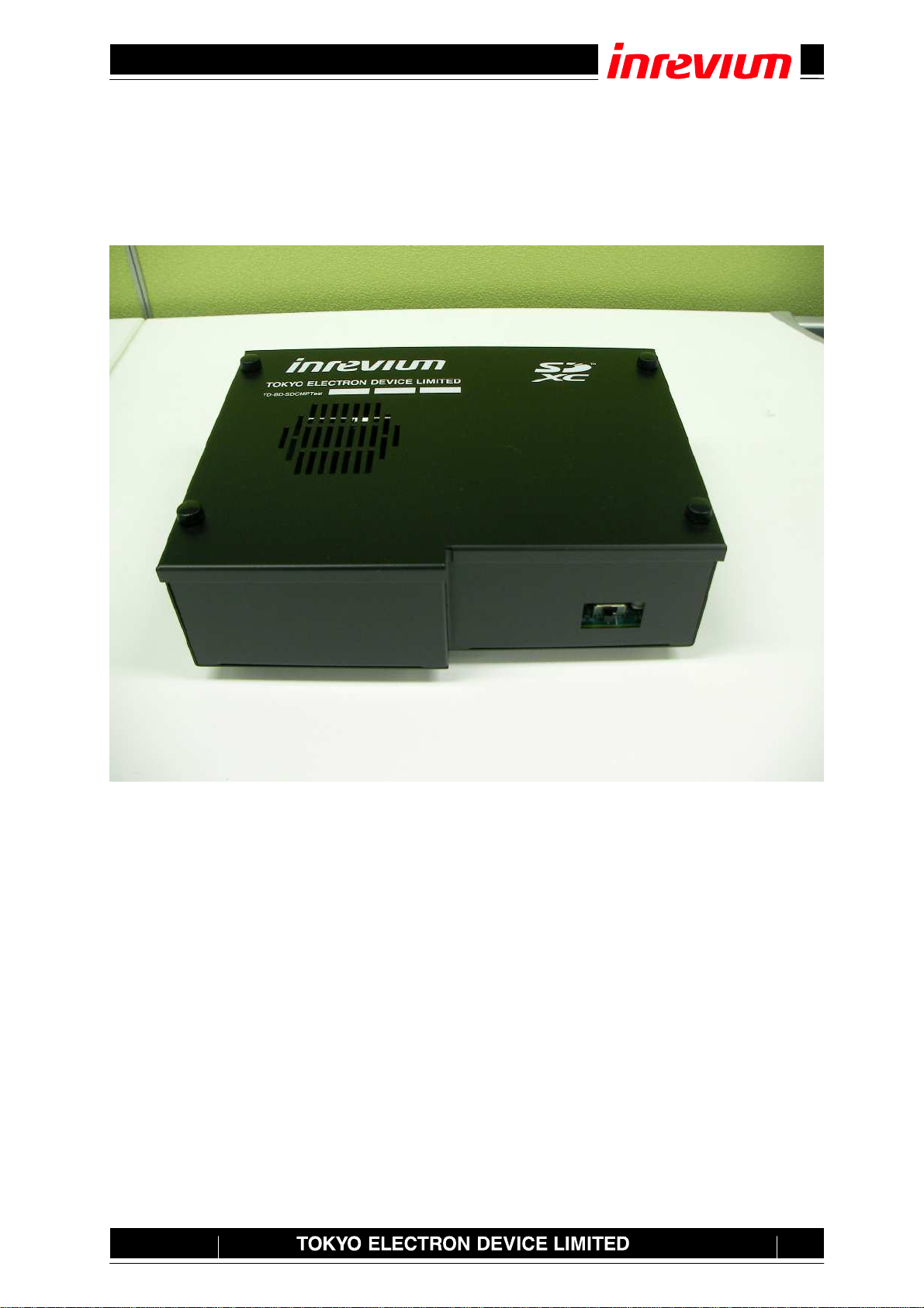
5.1.External View of the system
Figure 5-1 shows an external view of the system.
Figure 5-1External View of the TD-BD-SDCMPTestC system
It explains details in each part in the following chapters.
TD-BD-SDCMPTestC User’s Manual
13
Rev.
1.01
5.2.Description of Components
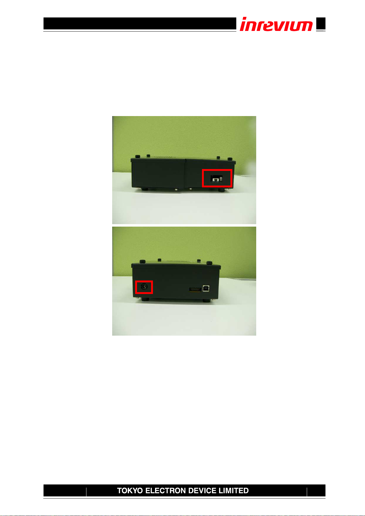
5.2.1. Power part
This system receives 12V from the AC Adaptor and creates a given voltage using a DC-DC converter
and a regulator. As shown in Figure 5-2, the input power to the system can be supplied by connecting
the provided AC Adaptor to the DC jack and turning the power switch on.
Figure 5-2Power Supply terminals
Power switch
DC Jack
TD-BD-SDCMPTestC User’s Manual
14
Rev.
1.01
5.2.2. JTAG connector
This system has a JTAG connector. It is usually unused, but it might be used when upgrade is done to
this system.
Figure 5-3JTAG connector

TD-BD-SDCMPTestC User’s Manual
15
Rev.
1.01
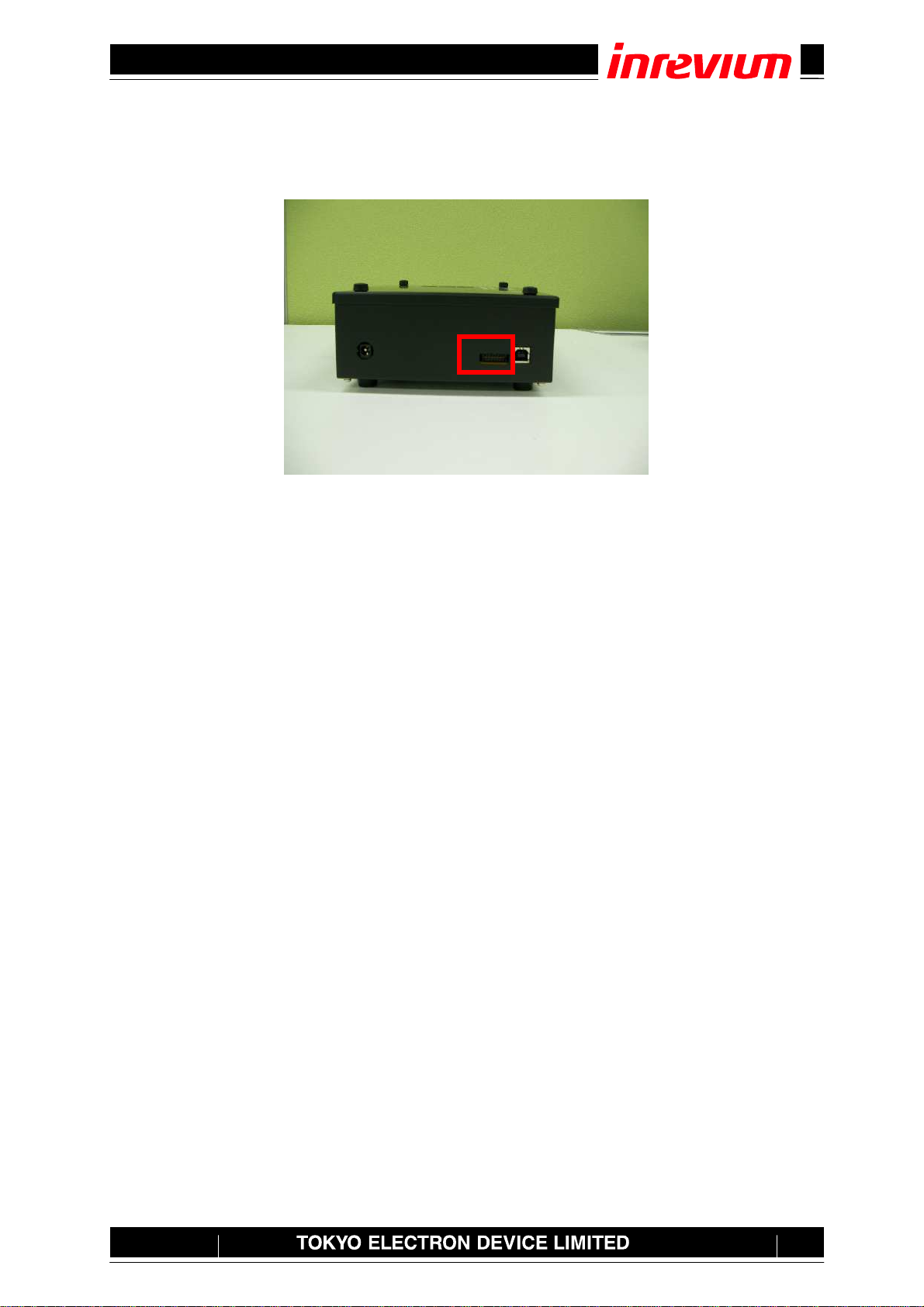
5.2.3. USB Interfaces
This system has a USB interface for system control. The USB connector is used to connect the USB’s
B-pin. Figure 5-9 shows the location of the connector.
Figure 5-4USB Interface

TD-BD-SDCMPTestC User’s Manual
16
Rev.
1.01
5.2.4. SD Memory Card Slot
This system has two SD Memory Card slots for SD Memory Card access. It can access the SD
memory card through this slot. Slot 2 is for the option and usually use slot 1. Moreover, SD slot 1 has
the temperature sensor inside it. So the temperature of SD slot 1 can be measured. Figure 5-5 shows
the location of each connector and header.
Attention 1: The temperature sensor chip is mounted in slot 1. There is a possibility of coming in
contact with the temperature sensor chip when the SD memory card is inserted, so please insert it
slowly.
Attention 2: The value measured with the temperature sensor becomes a temperature around SD slot
1. Moreover, the value is a reference value.
Figure 5-5SD Memory Card Slots
SLOT1SLOT2

TD-BD-SDCMPTestC User’s Manual
17
Rev.
1.01
5.2.5. SMA receptacles
This system has three SMA receptacles. SMA1 is used to transmit the trigger signal of the oscilloscope.
SMA2 and SMA3 are unused now. Figure 5-6 shows the location of each SMA receptacle.
Figure 5-6SMA receptacles
SMA1
SMA2
SMA3

TD-BD-SDCMPTestC User’s Manual
18
Rev.
1.01
5.2.6. SD Extension connector
This system has a SD extension connector. It is unused now. Figure 5-7 shows the location of SD
extension connector.
Figure 5-7SD Extension connector
TD-BD-SDCMPTestC User’s Manual
19
Rev.
1.01
6. USB Device Driver
6.1.Installation Procedure
This section describes how to install USB Device Driver.
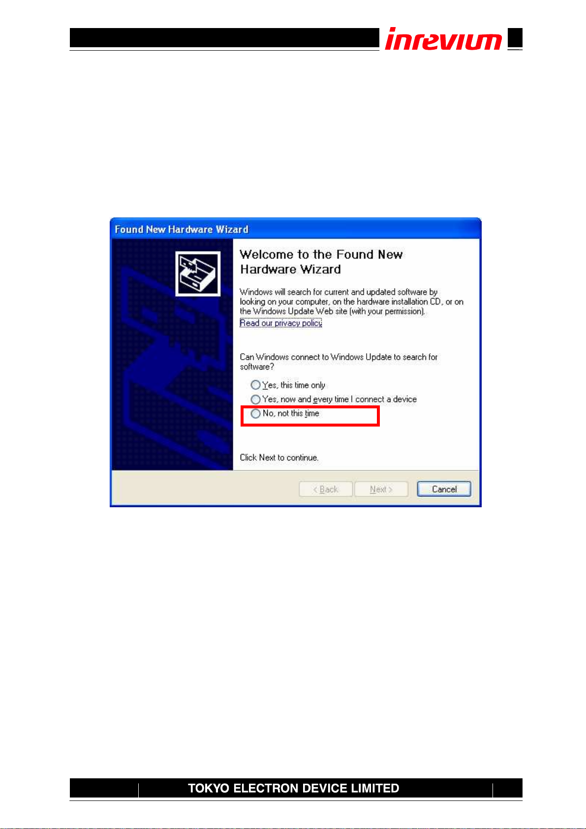
The driver software is stored in SOFT¥Release¥Sys immediately below Release Directory. Connect
a USB cable to your PC and turn on the power of the board. The Found new hardware wizard
appears in the task column.
Select “No, not this time”and click Next to continue.

TD-BD-SDCMPTestC User’s Manual
20
Rev.
1.01
Check “Install from a list or specific locations”and then click Next to continue.
Select “Search for the best driver in these locations”and check the “Include this location in
search”checkbox.
Click Reference and select a folder storing a suite of drivers.
¥Release¥Sys
Then click Next to continue.
Table of contents


