Open System CR-IP.1-4I User manual

"Diesel tester CR-IP.1-4I"
2020
Common Rail Injector Tester
Data sheet
Technical description
Instruction manual
Warranty card

"Diesel tester .CR-IP.1-4I" - Passport. Technical description.
2

3
Contents
1. Introduction
2. General information
3. Purpose
4. Main technical data and features
5. Device design
6. Operating instructions
7. Limitation of liability
8. Preparation for work
9. Operating the device
10. Updating the device software
11. Supply package
12. Warranty obligations
Appendix No. 1 Connector pinout X1
Appendix No. 2 Connector pinout X2
Appendix No. 3 Connector pinout X18
Appendix No. 4 Connector pinout X5
Appendix No. 5
Appendix No. 12 Warranty card.

"Diesel tester .CR-IP.1-4I" - Passport. Technical description.
4
1.
Introduction
This passport is a document certifying basic parameters and technical
characteristics of the "Diesel tester CR-IP.1-4I" controller for testing and verification of
performance of Common Rail system diesel injectors, guaranteed by the manufacturer.
This passport allows to get acquainted with the device, order and rules of its operation,
observance of which will ensure correct operation of the controller.
2.
General information
Diesel tester CR-IP.1-4I" controller is an electronic unit that controls electrical
elements of Common Rail fuel system. It is used as a part of the bench equipment, it is
controlled by "ARM-Diesel" software.
3.
Destination
Device "Diesel tester CR-IP.1-4I" is designed for diagnosing of Common Rail
system injectors manufactured by Bosch, Denso, Delphi, Siemens VDO on the stand.
The device provides:
•
•
control of electromagnetic injectors of light series from 14 V voltage;
•
control of electromagnetic nozzles of cargo series with supply voltage
of 28 V;
•
piezoelectric nozzle control;
•
control of Common Rail fuel injection engines of CP1, CP3 systems;
•
control of the measuring unit curtain;
4.
Main technical data and characteristics
•
Supply voltage, V - ~220 V ±15%;
•
Power consumption, W, not more than - 350 W.
•
Curtain control relay load - 5A 250V AC, 5A 24V DC;
•
•
Dimensions (width x height x depth) - 520x650x290 mm;
The "Diesel tester CR-IP.1I" can control 1 injector at a time, the "Diesel tester
CR-IP.4I" can control 4 injectors.
* Simultaneous control of 1-4 nozzles;
Unit weight: 5 kg;

5
5.
Device design
Figure 1.Front view of "Diesel tester CR-IP.1I"
Diesel tester CR-IP.1I" device is designed as a block. On the front panel of the
device there are:
•
X1 - injectors connection socket;
•
X2 - for connection of the injection sensor;
•
Power on toggle switch.
Figure 2.Front view of "Diesel tester CR-IP.4I"
Diesel tester CR-IP.4I" device is similarly designed as a block.
The front panel of the device contains:
•
X1 - injectors connection socket;
•
X2 - for connection of the injection sensor;
•
Power on toggle switch.

"Diesel tester .CR-IP.1-4I" - Passport. Technical description.
6
Figure 3.Rear view of "Diesel tester CR-IP.1-4I"
The rear panel of the device contains
•
X5 - pump control;
•
X18 - for connection of regulator and pressure sensor;
•
USB, ETH - for connection to a personal computer;
•
PROT - connection of the safety mechanism contacts;
•
Cooling fan;
•
"NETWORK" for connection of mains supply ~220 V.
6.
Operating instructions
Requirements for environmental conditions:
•
Operating temperature: +5ºC to +40ºC
•
Transport temperature: -20 ºC to +60 ºC
•
Relative humidity (non-condensing): Operational 8% - 80%, Storage
5% - 95%.
•
Air dust content: not more than 75 µg/m 3
Before switching on the device it is necessary to check visually or by means of
The"NETWORK"is structurally designed in one housing with fuse
devices, serviceability of connectors-adapters, 220 volt power cable.
If the appliance has been moved from a cold to a warm environment, it is strictly
forbidden to operate for 1-1.5 hours.

7
After switching on, allow the unit to run for 2-4 minutes and then start working.
Categorically forbidden:
•
switch on the device if the power supply cables are defective;
•
connect and disconnect adapter connectors from injector, sensor or
pressure regulator while the unit is on;
•
plug the device into a network that does not have an earthing circuit;
•
plug the device into the mains using a cable without an earthing
contact;
•
to use the device "Diesel tester CR-IP.1-4I" together with electrical
equipment that is not connected to the ground loop.
Failure to observe the last three points may result in electric shock.
In addition to health hazards, the lack of grounding, in most cases, leads to
failure of the pressure sensor, since the device uses a switching power supply,
according to the circuitry features of which, in the absence of grounding on the
device body will be voltage equal to half of the device supply voltage and becomes
110V.
7.
Limitation of liability
The manufacturer shall not be liable to the purchaser of this product or a third
party for damages or losses incurred by purchasers or a third party due to improper use
of the product, including inexpert or faulty operation of personnel, or for losses caused
by acts or omissions of this device.
Under no circumstances will the manufacturer be liable for any lost profits, lost
savings, losses due to accidents or other consequential economic losses, even if the
company has been advised of the possibility of such losses. The manufacturer shall not
be held liable for damages claimed by you based on third-party claims or caused by the
failure to perform your obligations.
The manufacturer shall not be liable for any malfunctions and damages resulting
from the use of additional devices recommended for use with this device, as well as its
modification, repair or conversion beyond the scope of the operating instructions,
including the use of a self-made adapter plug.

"Diesel tester .CR-IP.1-4I" - Passport. Technical description.
8
8.
Preparing for work
Before operating the Diesel tester CR-IP.1-4I, please read the operating
instructions carefully.
When preparing the unit for operation, carry out the following steps:
Perform an external inspection of the device and connecting cables. External
inspection of the device and connecting cables is carried out with power supply
disconnected and consists in detection of mechanical damage of the device and
connecting cables.
9.
Working with the device
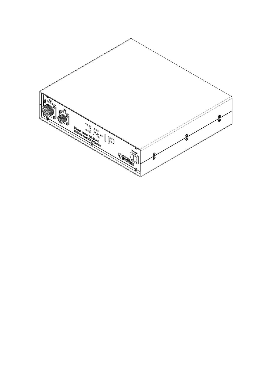
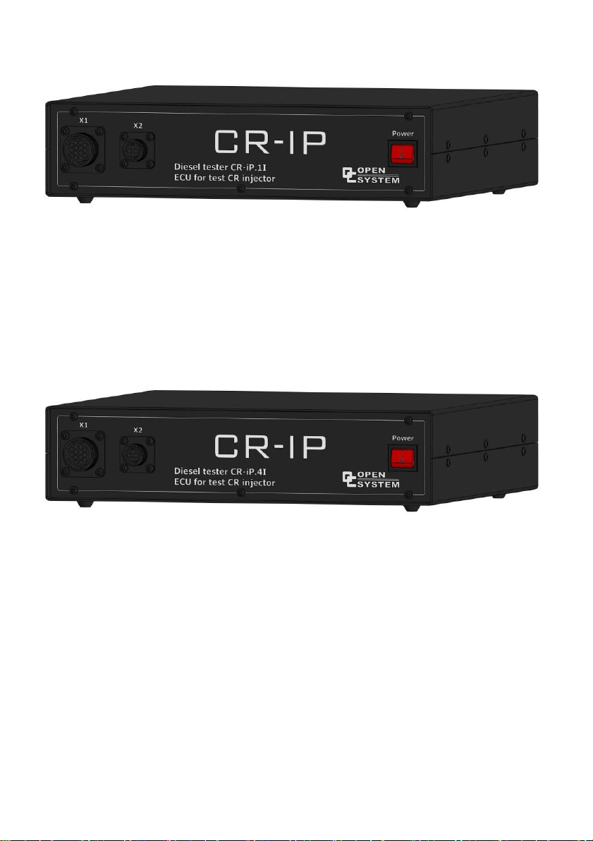
The "Diesel tester CR-IP.1-4I" device enables testing of electrically controlled
Common Rail system diesel injectors by means of controlling the regulating valve with
user-defined injector control signals and fuel pressure.
The device is controlled by means of software (hereinafter referred to as software)
on a personal computer (hereinafter referred to as PC).
To ensure continuous and trouble-free operation of the pressure regulator,
the maximum PWM value should be in the region of 35-40% in all operating modes
of the hydraulic system. This is achieved individually by selecting the ratio of pump
speed, pressure regulator and pump with its maximum volumetric capacity.
Ensuring security
In order to ensure the safety of the operating personnel, we strongly recommend
the use of passive protection elements in the system (various protective covers or shields
covering rotating parts and high-pressure lines). A convenient technical solution is to
make the enclosure, covering the rail and nozzles, from transparent plastic. End switches
must be installed on the opening elements.
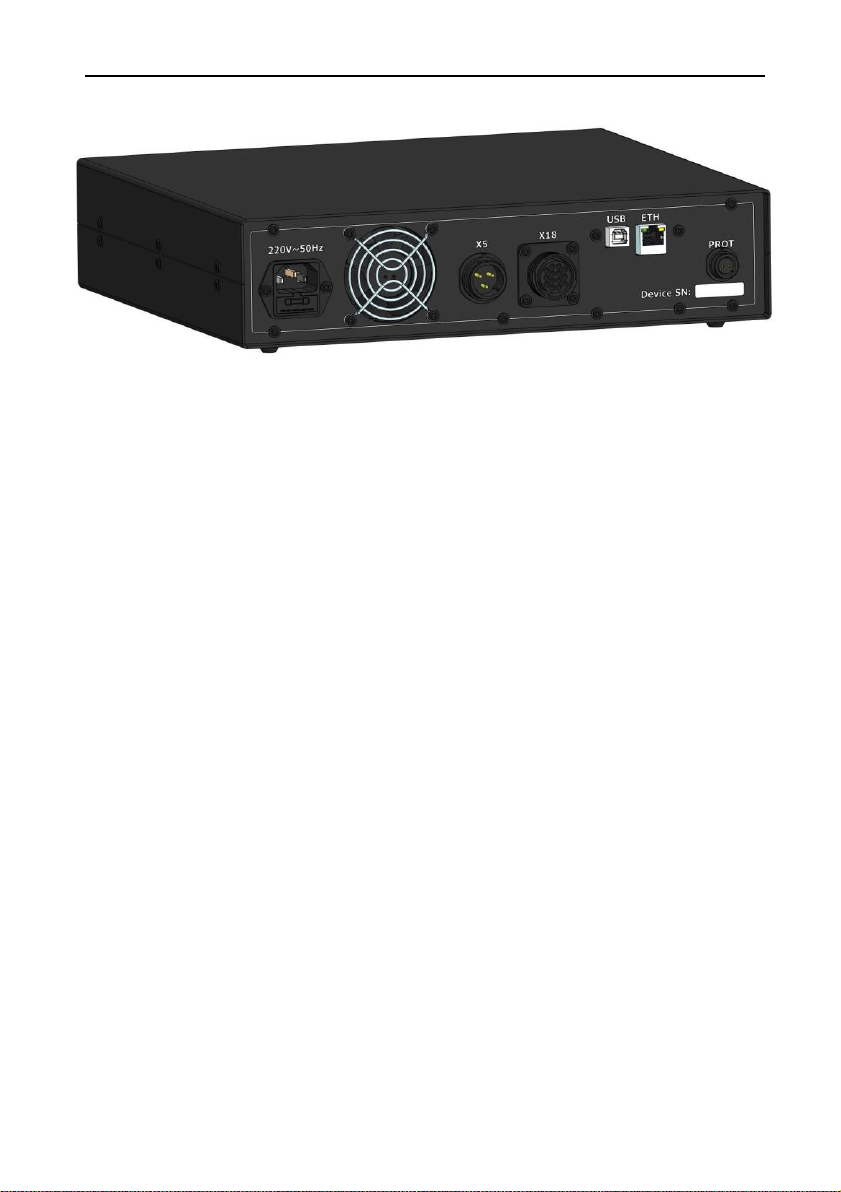
The device has an additional input "PROT" (from English - protection). Using
this input, the device determines whether the safety guards are closed or not. The device
wiring diagram is very simple and does not require any special skills for installation (see
appendix 5).
When working with injectors, the pressure is controlled only by the standard
high-pressure regulator mounted on the rail or on the pump of the CP1 system.
When using a CP3 system pump, a high pressure regulator rail must be
installed from the CP1 system.
Diesel tester CR-IP.1-4I" does not control the low pressure regulator of
pump CP3 in automatic mode.

9
It is also recommended for safety reasons to use a mechanical pressure limiting
valve with an actuation pressure corresponding to a maximum of 1800 or 2500 bar).
In case of breakage, unscrewing of screw joints or other failure of high pressure
fuel supply channels, immediately shut down the test bench, observing all safety
precautions.
10.
Updating the device software
Follow the steps below to update the device software:
1.
Connect the USB communication cable to the unit's connector and connect it to
the USB port of the PC.
2.
Connect the power cord to the power connector and to 220V/50Hz AC power.
3.
Turn on the unit with the power switch (see point 4).
4.
Start the PC and software to update the device. You will be taken to the updater
window:
6. Wait for the update process to complete.
Figure 4.Updating the software of the device
5.Click the button "Update the firmware!».
7. Close the updater window.

"Diesel tester .CR-IP.1-4I" - Passport. Technical description.
10
11.
Scope of delivery
Data sheet (Technical description, instructions operation).............................1 pc.
Controller "Diesel tester" ..............................................................................1 pc.
Connection cable for injectors........................................................................1 pc.
Adaptor cable for injectors.............................................................................4 pcs.
Cable for regulators and pressure sensor........................................................1 pc.
Connector for curtain/pump connection........................................................1 pc.
PROT1 connector..........................................................................................1 pc.
Power supply cable 220V..............................................................................1 pc.
Fuse 5A..........................................................................................................1 pcs.
Communication cable with PC......................................................................2 pcs.

11
12.
Warranty obligations
The manufacturer guarantees stable operation of the device "Diesel tester CR-
IP.1-4I" if the owner observes the rules of storage and operation stated in the present
certificate.
The warranty period is set by the manufacturer - 18 months from the date of
receipt of the product, with the exception of cases specifically agreed by the
manufacturer and the buyer in the additional contract.
In the warranty card, the manufacturer marks the year, month, day of sale, legal
address, telephone number of the company, which performs the warranty repair (the
warranty card is enclosed to the passport of the device "Diesel tester CR-IP.1-4I").
During the warranty period the owner is entitled to a free repair on presentation of
this passport and the warranty card. After repair, the list of troubleshooting works shall
be recorded in the warranty card.
The following is not a reason for complaint: breach of integrity of connecting
wires (cables-adapters).
The manufacturer is entitled to refuse the guarantee repair of the Diesel tester CR-
IP.1-4I in the following cases
•
The device has been tampered with and there are traces of tampering;
•
There are traces of mechanical damage on the casing or the electronic
board of the device;
•
There are foreign objects or liquids in the case or on the electronic board
of the device;
•
if the device is not stored and operated properly.
Without the warranty card and in case of violation of the seals on the product, no
claims to the quality of work and warranty repair will be made.
During the warranty period set for the product, repairs will be made at the owner's
expense if the product is not operated in accordance with these operating instructions.
The manufacturer provides further repairs of the Diesel tester CR-IP.1-4I after the
expiration of the warranty period under a separate contract.

"Diesel tester .CR-IP.1-4I" - Passport. Technical description.
12
CR-tester
1
GND
R
FUSE
+5V
CR-tester
X1 connector
Cont.
Chain
Cont.
Chain
1
Injector 1+
1
Injector 1+
2
Injector 1-
2
Injector 1-
1
2
Appendix 1 X1 connectorpinout
CR-tester
X1 connector
Cont.
Chain
Cont.
Chain
1
Injector 1+
1
Injector 1+
2
Injector 1-
2
Injector 1-
3
Injector 2+
3
Injector 2+
4
Injector 2-
4
Injector 2-
5
Injector 3+
5
Injector 3+
6
Injector 3-
6
Injector 3-
7
Injector 4+
7
Injector 4+
8
Injector 4-
8
Injector 4-
Figure 5.Nozzle connector (4 nozzles modification)
Figure 6.Nozzle connector (modification for 1 nozzle)
Appendix No. 2 X2 connectorpinout
Cont.
Chain
Chain
1
GND
1
GND
2
SIG
2
SIG
3
+5V
3
+5V
Figure 7.Injection sensor connection connector
1
2
1
2
1
2
1
2
1
2
3
Injection
sensor
Connector X2
Cont.
No. 1 injector
No. 2 injector
No. 3 injector
No. 4 injector
No. 1 Injector

13
CR-tester
GND
FUSE
+5V
CR-tester
FUSE
1
2
HP regulator
Appendix No. 3 X18 connectorpinout
1
Figure 8.Connection of rail pressure sensor and pressure regulators
Appendix No. 4 Connectorpinout X5
Figure 9.Connection to the curtain or pump control relay In series with the common
contact of the relay, a fuse is installed in the unit
to 5A. If the current consumption is higher, an intermediate relay should be installed.
2
LP regulator
1
Rail pressure
sensor
2
3
1
Curtain
control
2
3
Cont.
Chain
2
REG HP+
2
REG HP+
6
REG HP-
6
REG HP-
9
REG LP+
9
REG LP+
5
REG LP-
5
REG LP-
14
GND
14
GND
13
SIG
13
SIG
11
+5V
11
+5V
Cont.
Chain
Chain
1
REL COM
1
REL COM
2
REL NO
2
REL NO
3
REL NC
3
REL NC
Connector X18
Cont. Chain
Connector X5
Cont.

"Diesel tester .CR-IP.1-4I" - Passport. Technical description.
14
COM
NC
NO
CO
MNC
CO
MNC
NO
NO
Annex No. 5
Plug to
"PROT"
connector
Figure 10.Wiring diagram for safety limit switches
The operation of the circuit is designed for disconnection of the circuit.
Depending on the method of installation and design, take such contacts of the limit
switch so that when the safety guard is opened, the circuit connecting the two contacts of
the "PROT" connector is disconnected.
The contacts are marked as follows on the terminals:
•
NC - normally closed contact;
•
NO - normally open contact;
•
COM - common contact (it is connected to NC or NO, depending on whether the
button is pressed or not).
For example: take a limit switch like the one in the diagram (Fig. 6).
Install it on the door of the safety enclosure so that the button closes when the door is
closed and opens when it is opened.
Connect the wire from the first contact of the "PROT" plug to the COM
contact, and from the second contact to NO.
If it is necessary to install two or more limit switches (for several mechanisms),
connect them in series: from the "PROT" plug to the COM contact of the first limit
switch, from its NO contact, to the COM contact of the second limit switch, from its
NO contact to the next limit switch, according to the same scheme. From the last
terminal, lead to the second contact of the plug "PROT" (see Fig. 7).
The end switches must be insulated from the frame of the stand (do not
connect the common contact with the housing)!!!
Plug to "PROT"
connector
Figure 11.Wiring diagram with multiple limit switches

15
Appendix No. 12 Warranty card
Warranty card No.
.
Address
tel.
fax.
Date of sale "
Diesel tester CR-IP.1-4I device for testing and checking the performance of
Common Rail system diesel injectors.
Warranty repair and maintenance of the CR-IP.1-4I
controller is performed by the company

"Diesel tester .CR-IP.1-4I" - Passport. Technical description.
16
Table of contents
Other Open System Test Equipment manuals