RuiDeng UM34C User manual

Instructions for USB Tester with Full Colour Display
-Model: UM34/UM34C
Date:2019.9.25
Dear Customer,
Thank you for purchasing this Full Colour USB Tester from Hangzhou Ruideng Technologies Co.,
Ltd. Prior to using this product we recommended that you briefly familiarize yourself with these
instructions. In order to ensure the correct operation and use of the device. We also advise that
you keep these instructions in a safe place for future reference as may be needed.

Instructions for USB Tester with Full Colour Display.................................................................. 1
1.1Technical Parameters:............................................................................................................ 1
1.2 Function Interfaces................................................................................................................1
1.3 The Core Function:................................................................................................................ 2
1.4 Device Layout........................................................................................................................ 2
1.5 Interface Prompt Representing Functions............................................................................ 2
1.6 Operating Instructions.......................................................................................................... 3
1.6.1 Interface 1: Main Measurement Interface.( As shown below)................................. 3
1.6.2 Interface 2: Quick Charge Recognition Interface............................................................... 3
1.6.3 Interface 3: Charging Recording Interface................................................................. 4
1.6.4 Interface 4: Data Connection Cable Impedance Measurement Interface................ 4
1.6.5 Interface 5: Measurement Graphing Interface..........................................................5
1.6.6 Interface 6: System Parameter Setting Interface.......................................................5
UM34C Android APP Instruction................................................................................................ 7
2.1 APP Installation:.................................................................................................................... 7
2.1.1 APP download............................................................................................................ 7
2.1.2 APP installation.......................................................................................................... 7
2.2 Installation succeed...............................................................................................................8
2.2.1 APP Connection & Operation.....................................................................................8
2.2.2 APP interface.............................................................................................................. 9
UM34C IOS APP Instruction...................................................................................................... 11
3.1 APP Connection & Operation..............................................................................................11
3.2 APP update.......................................................................................................................... 11
Appendix 1: Explanation of terms.............................................................................................12
Appendix 2: Basic Operational Knowledge............................................................................... 12

1
1.1Technical Parameters:
Model: UM34/UM34C
Display screen:1.44 Inch color LCD display
Voltage measurement range:4-24.00V
Voltage measurement resolution:0.01V
Current measurement range: 0-4.000A
Current measurement resolution: 0.001A
Capacity accumulation range: 0-99999mAh
Voltage measurement accuracy:±(0.2%+1digit)
Energy accumulation range:0-99999mWh-999.99Wh
Current measurement accuracy:±(0.8%+3digits)
Load impedance range: 0.8Ω-9999.9Ω
Time measurement range:0-99h59min59s
Temperature range:-10℃~100℃/0℉~200℉
Temperature measurement error:± 3℃/ ± 6℉
Screen brightness setting: Levels 0-5
Delay off the screen time:0-9minutes
Voltage graphing range: 4-24.00V
Current graphing range:0-4.000A
Product weight:22.87g(UM34C)/18.39g (UM34)
Refresh rate: 2Hz
(No packaging);51.43g(UM34C)/46.95g (UM34)( With packaging)
Dimensions:71.2mmx30.5mmx12.4mm(UM34C)/71.2mmx30.5mmx11.3mm(UM34)
Quick charge recognition mode:QC2.0、QC3.0、APPLE 2.4A/2.1A/ 1A/0.5A、Android DCP、SAMSUNG
(Note:This quick charge agreement recognition model is for reference only, because cell phone upgraded quickly, it
can't be absolutely accurate identification
)
USB port: USB 3.0 port , support OPPO phone VOOC, OnePlus DASH
1.2 Function Interfaces
Measurement Main
Interface
Quick Charge Recognition
Interface
Charging Recording
Interface
Data Connection Cable
Impedance Measurement
Interface
Measurement Graphing
Interface
System Parameter Setting
Interface

2
1.3 The Core Function:
USB 3.0 port
Quick Charge Recognition
With Chinese and English help interface
Android Phone APP Control
Data Record and Store
Capacity/Energy Detection
Rotate the screen in 4 directions
Voltage/Current/Power Detection
Differential Voltage Method Measurement Cable Impedance
Load connecting detection function (screen auto off, plug the load, screen auto lighting)
1.4 Device Layout
A:Micro USB Port
B:Multifunction buttons (4 pieces)
C:Bluetooth Switch
D:USB 3.0 A Female Port
E:USB 3.0 A Male Port
F:Type-C Input Port (Only VBUS、GND、CC1、CC2 four wires)
F:Type-C Input Port (only for USB to Type-c to measure cable resistance)
G:1.44 Inch Color Screen
H:Bluetooth Indicator: When connected to the host computer control software, the Bluetooth
indicator changes from flashing to steady state. When connecting, the Bluetooth icon is displayed
on the screen. (Bluetooth communication version only).
1.5 Interface Prompt Representing Functions
I:
Press and hold the key to rotate the Screen Left
J:
Press the key to close the screen
K:
Press the key to open the help interface
L:
Press and hold the key to rotate the screen right
M
Press PREV key to previous page
N:
Press NEXT key to next page

3
1.6 Operating Instructions
When the unit is first powered on the
welcome screen is displayed followed shortly by
the main interface screen.
Hidden interface: Pressing any button whilst
powering on the module will display four
options. Option 1 selects the Chinese Interface
and option 2 selects the English interface.
The third option is to reset (after reset, system setting data was restored to the factory
setting, all the stored data was not reset), The four option is to zero the Current reading (Ensure
there is no load connected to the unit). Release the button at the desired selection. Pressing and
holding the button after stepping to the four options will exit the hidden interface.
1.6.1 Interface 1: Main Measurement Interface.( As shown below)
O:Voltage Measurement
P:Current Measurement
Q:Accumulated Capacity
R:Accumulated Energy
S:Temperature Measurement
T:Number of the Data Group in use
U:Load Equivalent Impedance
V:Power Measurement
Press the ‘ ? ’ button to enter the interface as shown above:
Press and hold the ‘NEXT’ button to switch Data Group. The USB tester can provide a total of 10
groups of data to save and view. These are numbered 0-9.
With Data Groups 1-9 selected the current
mAh and mWh are saved after power off.
They will continue accumulating the next time
the tester is powered on. When the data
group selected is 0 then the current value of
mAh and mWh will be temporarily saved at
power off. When the device is next powered
on these values will be recalled and will begin flashing.When the accumulated mAh exceeds 1
mAh, the previous data will be cleared and accumulation will restart.
With a Data Group selected, press and hold the ‘PREV’ button to clear the mAh and mWh.
(As shown)
Press ‘NEXT’ to switch to the Quick Charge Recognition Interface.
1.6.2 Interface 2: Quick Charge Recognition Interface
W:D +: (DP) data positive signal level.
X:D-: (DM), data negative signal level.
Y:Mode display

4
The product will automatically identify a device with a supported fast charging mode. At this
time the device supports the QC2.0 、QC3.0 、APPLE 2.4A/2.1A/ 1A/0.5A 、Android DCP 、
SAMSUNG.(Note:This quick charge agreement recognition model is for reference only, because cell phone
upgraded quickly, it can't be absolutely accurate identification
)
Press ‘NEXT’ to switch to the Charging Recording Interface.
1.6.3 Interface 3: Charging Recording Interface
Z:Accumulated Capacity
AA: Accumulated Energy
AB:Time display:The total accumulated
recording time.
AC :Capacity/Energy statistics trigger
current
AD:REC:recording status indicator.
‘REC’ displayed in red indicates that
recording is stopped. ‘REC’ displayed in green indicates that recording is in progress.
After power on, when the current flowing is greater than the Low Current trigger value. The
system automatically begins to record the accumulated capacity, energy, and time elapsed. The
‘REC’ indicator will change from red to green.
To set the Current trigger value, press and hold the "Next" button to highlight the value then
press the ‘PREV’ button to adjust the value as required. The value can be set anywhere between
0.01A- and 0.30A. (10mA to 300mA).
Press "Next" button to switch to the Data Connection Cable impedance Measurement Interface.
1.6.4 Interface 4: Data Connection Cable Impedance Measurement
Interface.
AE :USB Tester directly connected to
the power supply with Voltage and
Current values displayed
AF :USB Tester connected via a data
connection cable with Voltage and
Current values displayed.
AG:Data Connection Cable resistance.
Measurement procedure:
First, connect the USB Tester directly to the power supply and adjust the appropriate load
current (recommended value 1A) . Press and hold the ‘NEXT’ button to begin recording data. The
indicator prompt will stop flashing .
Second, unplug the USB Tester and then reconnect it to the power supply via the Micro
USB/Type-C IN data connection cable and adjust the load current to the same value as in the first
step. Press and hold the ‘NEXT’ button to begin recording data. The indicator prompt stops
flashing and the Data Connection Cable resistance measurement test is completed and the value

5
displayed.
Note: If during the second step the screen turns black, this indicates that the voltage difference is too high
and the tester will enter the 4V power-down state. You can reduce the current and then re-start the
measurement from the first step. After the Data Connection Cable resistance test is completed, the Tester needs
to be powered off and then power on again to resume measurement.
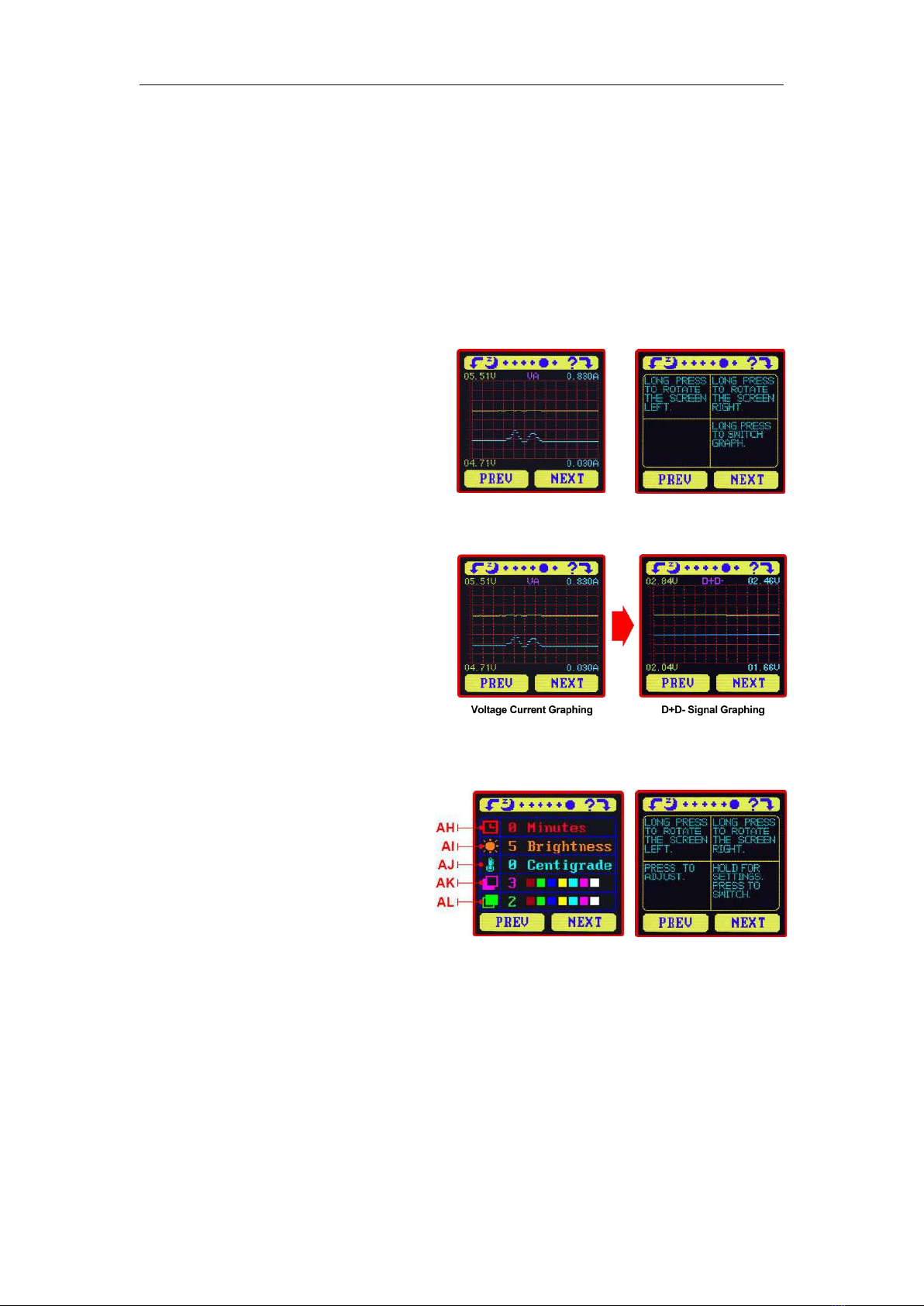
Press the ‘NEXT’ button to switch to the Measurement Graphing Interface.
1.6.5 Interface 5: Measurement Graphing Interface
This interface displays the voltage
measurement over time in the 4-24V range
and will automatically adjust the displayed
range in real time to account for voltage
fluctuations. And the current measurement
over time in the 0-5.000A range and will
automatically adjust the display range in real time to account for current fluctuations.
Press and hold “NEXT” to switch to D+D- graphing, as picture show
This interface displays the D+ /D- voltage
measurement over time in the 0-3.3V range
and will automatically adjust the displayed
range in real time to account for D+/D-
voltage fluctuations.
Press the ‘NEXT’ button to switch to the
system parameter setting interface.
1.6.6 Interface 6: System Parameter Setting Interface
AH:Auto screen off time
AI:Screen brightness
AJ:Temperature display C /F
AK:Theme background color
AL:Theme foreground color
Press and hold the "Next" button to
enter into setting state, press “NEXT”
button to step through the options of auto screen off time, brightness level, temperature display
units, theme background color and theme foreground color. Stop on the value you wish to change
then press the "PREV" button to change the setting.
For auto screen off time setting press ‘PREV’ to repeatedly step though the 10 options from 0
to 9 minutes. Default time is 1 minutes.
For the screen brightness setting, press ‘PREV’ to repeatedly step though the 6 options from 0
to 5 where 0 is the lowest brightness level and 5 is the highest. Default brightness is 4.
For the temperature display units, pressing the ‘Next’ button toggles the setting between C
and F. default temperature unite is C.
For theme background color, press ‘PREV’ to repeatedly step though the 7 options from 0 to 6

6
where the color sequence is red, green, blue, yellow, light blue, pink, white and black. Default
color is 2, blue.
For theme foreground color, press ‘PREV’ to repeatedly step though the 7 options from 0 to 6
where the color sequence is red, green, blue, yellow, light blue, pink, white and black. Default
color is 6, white.
At any setting state, press and hold the ‘Next’ button to exit the settings menu.

7
UM34C Android APP Instruction
2.1 APP Installation:
NOTE:The APP only support Android 5.0 and above
2.1.1 APP download
There are 2 download ways:
①APP download link : http://www.mediafire.com/folder/5c877rc21tp1p/UM34, choose UM34C
android APP file to download, you can use the computer to download , then sent the phone, or
use the phone download directly.
② Search “UM Meter” on Google Play and click download.
2.1.2 APP installation
(1)
(2)
(3)
(4)

8
2.2 Installation succeed
After Installation APP icon as the picture
2.2.1 APP Connection & Operation
Click APP Icon, APP will start, the system will detect automatically that the App will be updated or
not. There is popup to remind updating, as picture show.

9
2.2.2 APP interface
After update, APP main interface is as the following picture:
Picture01
Picture02
AN: Export data to the phone folder (mobile phone memory or SD card root directory, repeat
writing, can directly generate graphs in Excel), and can share files to other APP (picture 2)
AO: Muti-language option, click to select languages, currently 22 languages (简体中文 /繁体中
文), English, русский, Polskie, español, ⺁, Slovenskýjazyk,Latvietis, 日 本 語 , Deutsche,
Nederlands, 한국어 , Français, Türk, 」, Bahasa Indonesia, čeština, Українська,Ελληνικά,
Magyar, Português...), more languages are constantly being updated.
AP: Bluetooth connection: Click to enter the device selection, search for the Bluetooth name of
the device, enter the pairing code 1234, click the connection (first connection, first set the
Bluetooth connection on the phone, then open the APP and click the Bluetooth icon to connect.)
AQ: Program information: version number description, assist developer information
AR: Voltage-current measurement curve
AS: Voltage Measurement
AT: Current Measurement
AU: Accumulated Capacity
AV: Load Equivalent Impedance

10
AW: mAh
AX: mWh
AY: recording time
AZ: Off current
BA: Data group number(click the triangle to switch data group)
BB: Accumulated capacity
BC: Accumulated energy
BD: Quick charge recognize mode
BE: Voltage on D+ data cable
BF: Voltage on D- data cable
BG: Screen brightness adjustment
BH: Screen off delay adjustment
BI: Temperature display(℃/℉)
BJ: Switch to previous page
BK: Rotate key: rotate the screen
BL: Delete key: clean the data group being used
BM: Switch to the next page
Note:
1. Due to the wide variety of Android phones, the UI interface is displayed differently on
different scale screens of Phones.
2. Application permission requirements, allow the necessary permissions when the program is
installed (allow background running, allow Bluetooth, allow operation of the folder, allow reading
of the application list, etc.) and also set the permissions of the program in the phone after
installation: Allow background running, The lock screen operation won’t shut down the APP,
self-starting is allowed, etc. (the system is prevented from forcibly exiting the APP when data is
continuously recorded).
3.Language selection memory, you only need to select the language when you open the app for
the first time.

HangZhou RuiDeng Technologies Co., Ltd
11
UM34C IOS APP Instruction
Apple APP only supports the official version system of IOS8.0 or above. Search "UM Meter" in
the Apple Store to download.
3.1 APP Connection & Operation
After opening the app, click “Find” to search a nearby Bluetooth device. After the screen
prompts the connection is successful, click the “data communication” to go to the second page.
The table can be zoomed in and out. Other functions are the same as Android APP. After clicking
“Export”, the curve can be exported to a form file. Click “Share” in the “personal center” to copy
the form file to other apps to open or share. Click “Language” on the personal center to choose
language, you can choose English, Simplified Chinese, Traditional Chinese, Russian, Japanese,
German, Korean, French, Spanish, Polish, Hindi, Slovak, Latvian, Dutch, Turkish, Ukrainian,
Ukrainian, Thai, Indonesian, Czech, Hungarian, etc. Click “Help” to learn about simple operation.
3.2 APP update
When there is a large version update, the software will automatically prompt for the update,
or you can get the latest software from the Apple Store. The IOS APP version corresponding to
the current manual is 1.2.1

HangZhou RuiDeng Technologies Co., Ltd
12
Appendix 1: Explanation of terms
Quick charge: fast charging, modern fast charging mostly refers to the charging process
when the charging current is greater than 2A or the charging power is greater than 10W.
Quick Charge Protocol Detection: Detect which quick charge protocols are supported by
the charger.
Quick Charge Protocol/Quick Charge Mode Recognition: Identify what fast quick is
currently in progress.
Decoy/trigger: Simulates a quick charge protocol sequence that allows the charger to
output high voltage/high current.
Quick Charge Simulation: Analog protocols which chargers do not support to improve
charger compatibility.
Common part of the quick charge agreement:
Qualcomm: QC2.0, QC3.0, QC4+
Media Tek: PE2.0, PE3.0
Huawei: FCP SCP
OPPO: VOOC, Super VOOC
One plus: DASH, Warp
USB Type-C: PD2.0, PD3.0, PPS
mAh, mWh: milliampere hour, milliwatt hour, milliampere is the capacity unit. Milliwatt hours is
the unit of energy.
Appendix 2: Basic Operational Knowledge
I: measure the capacity of power bank
Preparation materials: power bank to be tested, USB tester, HD35 electric load or mobile
phone, charging head.
the data need to view:the capacity energy value of the power bank (mAh mWh), the
voltage and current value of the power bank output
First charge the power bank, then adjust the current meter to the non-zero data group,
then use the power bank to charge the mobile phone or use the HD35 electronic load to
discharge to the power bank to automatically shut down, use the charging head to supply
power to the tester, and then Record the mAh, mWh values on the tester.
Method 1: The comparison tester shows that the mWh is divided by efficiency (like 90%)
and the power bank mWh. If the difference is not large, the capacity of power bank is real (the
most accurate method).
Method 2: If the mobile phone is 5V charging, the tester displays mAh multiplied by 1.5. If
the mobile phone is a 9v charging tester, the mAh multiplied by 2.7. If the value is not much
different from the technical parameter of power bank. The power bank’s capacity is real. (only
applicable to power bank without mWh).
Since many mobile power sources are currently tens of thousands of mAh, if you simply
charge the mobile phone to measure the capacity of the power bank. You need to charge the
mobile phone many times. It takes even a week to measure the capacity of power bank, in

HangZhou RuiDeng Technologies Co., Ltd
13
order to quickly discharge the power of the power bank. Test with a constant current load. Take
xiaomi power bankII as an example, it can support 5V/2A output, 38.5Wh/(5V*2A)=3.85. It can
discharge the power of power bank in about 4 hours. If you use HD35 electronic load, it can be
triggered 9V. Thus 18W quick discharge, 38.5Wh / (9V * 2A) = 2.13h, so that it takes only two
hours to complete the power bank capacity test, quickly identify whether the capacity of power
bank is false (high power discharge, inversion rate will decrease and the actual measured
capacity will be smaller).
II. Measuring the quality of data cable
The quality of the data cable directly affects the speed of charging, even worse the inferior
data cable has the risk of burning the phone, so measuring the quality of the data cable is also
a necessary function. We have two ways to measure the quality of the data cables, each with
its own advantages and disadvantages, you can choose the better way which suits you .
The common data cable length has a great influence on the actual test results. Generally
speaking, the shorter cable ‘s performance should be better.
1. Current measurement method:
Test materials: mobile phone, original charger, original data cable, USB tester, data cable to
be tested.
Test procedure: Discharge the phone to between 50% and 60% power. Use the original
charger, USB tester and original data cable to measure the charging current and record this
current. Then replace the original data cable with the data cable to be tested, and record the
charging current again. The time between the two measurements should not be too long. The
higher the charging current, the better the quality of the line. If the charging current values
differ a lot, it may indicate that the quality of the cable is very bad or the mobile phone is not
supported to the cable(Note: you must use UM25 to test Huawei Super Quick Charge).
2.Cable resistance measurement method:
Test materials: charger, UM series tester, constant current load (such as HD35), data cable
to be tested.
Test procedure: Insert the tester into the charger,switch to the line resistance measurement
interface, plug in the load, adjust the current to about 1A, hold the button and wait for the tester
to flash, then remove the tester.
Connect the data cable. Plug it into the charger, plug the other end of the data cable into the
tester input, turn on the load, and hold the button. The resistance of this cable will be displayed
on the tester.
Advantages of current measurement method: It can intuitively judge whether the data cable
supports the fast charge and fast charge current value, and you only need to buy a USB tester.
Disadvantages of current measurement method: relying on mobile phones and original
accessories of the phone as a comparison.
Advantages of line resistance measurement: It is possible to measure the actual parameters
for comparison between different wires. Generally, the micro data line resistance will be above
400mΩ, and the Type-C data line can be made smaller. No need to use a mobile phone for
measurements
Disadvantages of line resistance measurement: the tester and load are required to measure,
and the price is higher.
This manual suits for next models
1
Table of contents
Other RuiDeng Test Equipment manuals
Popular Test Equipment manuals by other brands

YOKOGAWA
YOKOGAWA CA330 user manual

Keysight Technologies
Keysight Technologies N1091 CA Series Getting started

Maddox
Maddox MH20B-1 Owner's manual & safety instructions

Test Equipment Depot
Test Equipment Depot GOS-620 Operation

ANSMANN
ANSMANN PowerCheck 12/24V quick guide

Cablescan
Cablescan 90 Series Setup manual