Insect Detection Systems IDS-2020L Manual

IDS-2020L Operator’s Guide
IDS-2020L
Operator’s
Guide


IDS-2020L Operator’s Guide
Acknowledgements
Microsoft® is a U.S. registered trademark of Microsoft
Corporation.
Windows™ is a trademark of Microsoft Corporation.
All other trademarks and brand names are the property of
their respective proprietors.
Notice
The information contained in this manual is subject to
change without notice.
Insect Detection Systems, Inc. makes no warranty of any kind
about this material, including the
implied warranties of
merchantability and fitness for a particular purpose.
Insect Detection Systems, Inc. shall not be liable for
errors contained herein or for incidental or consequential
damages in connection with the furnishing, performance,
or use of this material.
Copyright
This material is copyrighted. All rights are reserved. No
part of this manual may be photocopied or reproduced
in
any form without the prior written consent of Insect
Detection Systems, Inc.
Copyright 2001-2020 by Insect Detection Systems, Inc.

IDS-2020L Operator’s Guide
Table of Contents
1G E N E R A L I N F O R M A T I O N ------------------------1
Introduction............................................................... 1
Customer support...................................................... 3
Acoustic emission..................................................... 4
Emission types and waveforms............................. 6
RMS...................................................................... 10
Interaction between gain and threshold............. 12
Further reading........................................................ 15
ASTM standards on AE ........................................ 15
US code groups ................................................... 17
2G E T T I N G S T A R T E D --------------------------------- 2 0
Unpacking your IDS-2020L...................................... 21
Identifying the parts................................................ 21
Connectors .......................................................... 21
Battery compartment .......................................... 24
LCD module.......................................................... 26
Keypad................................................................. 26
Status indicator ................................................... 29
Connecting the sensor ............................................ 30
Connecting the AC or battery power ...................... 33
Powering up............................................................. 34
Default settings ................................................... 34
Verifying the instrument is working.................... 35
3M A N U A L O P E R A T I O N ------------------------------3 7
Operating modes ..................................................... 37
HITS Mode (Rate) ................................................ 37

IDS-2020L Operator’s Guide
HITS Mode (Tot.).................................................. 38
RMS Mode ............................................................ 38
Instrument states and LCD screens ....................... 39
Powering up......................................................... 39
Idle ....................................................................... 39
Acquiring data ..................................................... 40
Setting up ............................................................ 43
Sleep mode .......................................................... 43
Setup ....................................................................... 44
Mode keypad selection........................................ 44
Setup keypad selection....................................... 45
Test Period ....................................................... 45
RMS Alarms ...................................................... 46
Gain keypad selection......................................... 47
Filter In/Out keypad selection ............................. 48
Store keypad selection........................................ 48
Recall keypad selection ...................................... 49
Operations ............................................................... 51
Start/Stop keypad selection ................................ 51
Store keypad selection........................................ 51
Data point types............................................... 51
Storing data points........................................... 52
Filling the data logger ...................................... 53
Recall keypad selection ...................................... 54
Data set number............................................... 54
Point number .................................................... 55
Recalling data points ....................................... 56
Traversing the stored data points ................... 58
Clear keypad selection........................................ 58

IDS-2020L Operator’s Guide
Clearing current data ....................................... 59
Clearing logger data......................................... 59
Cancel .............................................................. 60
Battery status.......................................................... 61
Invalid values .......................................................... 61
4S O F T W A R E O P E R A T I O N----------------------- 6 4
USB drivers and link................................................ 64
Windows host program............................................ 66
Features............................................................... 66
Menus and Toolbars ......................................... 67
Setups ..................................................................
67
Data logger and message windows ................. 68
Chart windows ................................................. 70
Data files .......................................................... 72
Post-processing................................................ 74
Reports.................................................................
74
Installation........................................................... 76
Quick start........................................................... 77
User’s guide......................................................... 79
HyperTerminal program .......................................... 80
AS P E C I F I C A T I O N S-------------------------------------- 8 2
Physical ................................................................... 82
Display ..................................................................... 82
Indicators ................................................................ 83
Connectors .............................................................. 83
Electrical .....................................................................
83
Measurements......................................................... 84
BA C C E S S O R I E S --------------------------------------------- 8 6
Sensors.................................................................... 86

IDS-2020L Operator’s Guide
Probes..........................................................................
86
Preamps.......................................................................
89
Magnetic Holder ...................................................... 89
CH Y P E R T E R M I N A L P R O G R A M - - - 9 3
Starting HyperTerminal ....................................... 93
Setting up ............................................................ 94
COM port .......................................................... 94
COM port properties......................................... 94
Saving the configuration.................................. 94
Logging data to a file ....................................... 95
Acquiring data ..................................................... 95
Uploading stored data ......................................... 97
Viewing logged data............................................ 97
IDS-2020L command set...................................... 98
IDS-2020L data formats..................................... 101
Data packet types .......................................... 101
Hits packet structure..................................... 102
RMS packet structure .................................... 102
Inquiry packet structure ................................ 103
Upload packet structure ................................ 105
G L O S S A R Y---------------------------------------------------------- 1 0 8
I N D E X--------------------------------------------------------------------- 1 1 2

IDS-2020L Operator’s Guide
C
General Information
ongratulations on the
purchase of your new
IDS-
2020L! This section
describes the IDS-2020L
and its applications,
provides customer support
information and gives a
quick overview
of acoustic
emission terminology. If you
are eager to
begin using your IDS-2020L, you
may skip ahead to
Section 2, Getting Started.
Introduction
The IDS-2020L is our third-generation hand-held
instrument incorporating signal processing for pulsed and
continuous acoustic emission (AE). This
rugged unit is
designed to go anywhere and handle a great variety of
demonstrated industrial uses.
Applications include
▪Insect pest detection (wood and food products)
▪Leak detection (contact and airborne)
▪Valve leak monitoring
▪Machinery health monitoring
▪Cavitation detection in pumps and piping
Section
1

IDS-2020L Operator’s Guide
▪Transformer partial discharge detection
▪Acoustic emission testing of
▪CNG cylinders
▪Metals
▪Composites
▪Rock and soil
▪Wood products
▪Sensor and cable check for AE field test crews
Features include
▪Battery (single 9 V) or AC operation
▪Low power consumption, auto turn off
▪Keypad operator controls
▪Microprocessor controlled
▪4-line x 16-character LCD module with backlight
▪Thresholder signal processing (counts, hits)
▪RMS signal processing (0-5 V DC)
▪Wide bandwidth –1 kHz to 2 MHz
▪Switched bandpass filter (optional ranges)
▪Flexible gain adjustment (0-60 dB)
▪+24 V DC power out for preamps
▪Demodulated audio output
▪Buffered AC signal output
▪Store four setups for different applications

IDS-2020L Operator’s Guide
▪Store 4,000 data points
▪USB output for data logging to computer
or uploading stored data
▪Windows-based data logging software
Please refer to Appendix A for complete specifications
for the IDS-2020L.
Customer support
Customer support is available by sending e-mail to:
To speak with a customer support representative,
please
call: (407) 620-0011 or (412) 418-1890
You can also contact customer support by writing to:
Insect Detection Systems, Inc.
630 Brookfield Loop
Lake Mary, FL 32746-3745
Please visit us at our website:
www.insectdetectionsystems.com

IDS-2020L Operator’s Guide
Acoustic emission
Acoustic emission (AE), as defined by the ASTM E
610-82 standard, is:
“The class of phenomena whereby transient elastic energy is
generated by the rapid release of energy from a localized source or
sources within a material, or the transient elastic wave(s) so
generated.”
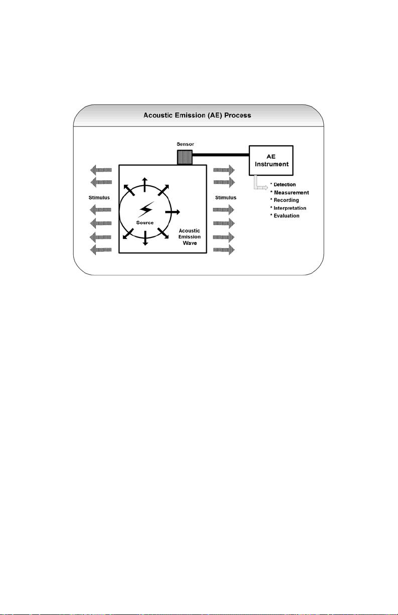
Acoustic emission testing is a technique that detects
active defects using passive methods. Stressing the test
material through service test or a separate stress test
provides the defect activity. Active defects cause
deformations within the test material to generate elastic
waves (Figure 1).
If you place a piezoelectric sensor into contact with the
material producing the acoustic emissions, the sensor
converts the sound waves into small variations of voltage.
A preamplifier at the sensor amplifies the signal the
sensor detects. This amplified signal is a continuous,
low
amplitude background noise with occasional or regular
acoustic emission hits. This emission detection,
conversion, and signal amplification process results in a
measurable acoustic emission signal that can be
processed
and classified to provide important information about the
material, the load, and their
relationships.
The following subsections discuss acoustic emission
types
and define terms. Please refer to the Glossary for an
extensive list of terms and definitions.
Figure 1. Overview of the acoustic emission process.
IDS-2020L Operator’s Guide
Emission types and waveforms
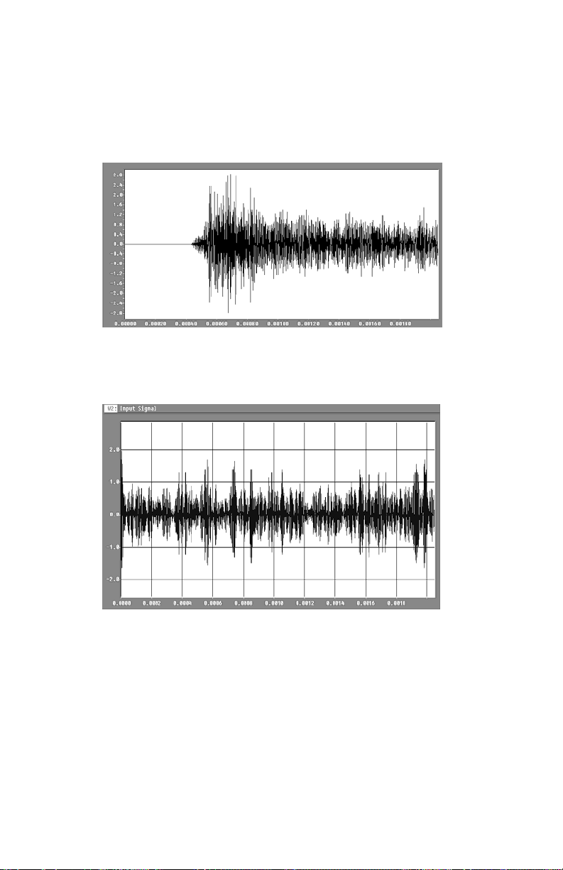
There are four basic types of acoustic emission (see
Figures 2 through 5). Figure 2 shows and example of
continuous acoustic emission. This type is best measured
as RMS and the next subsection discusses this in detail.
Burst-type emission, shown in Figure 3, is best
characterized by threshold crossing detection. An acoustic
emission processor compares the acoustic
emission signal
voltage with an internally generated
reference voltage
called the threshold (see Figure 6).
Each time the acoustic emission signal exceeds this
threshold voltage level, the detecting device’s comparator
emits a pulse. A pulse represents a ringdown count or
count. The processing device sums up the pulses,
providing the total counts for a given time interval. In
addition, each pulse from the comparator triggers a time-
delay circuit, which is the hit detector.

IDS-2020L Operator’s Guide
The detector stays
on as long as it detects pulses from the
comparator.
When it fails to detect a pulse within a specified time
period, or timeout, the detector turns off and
registers
the preceding pulses as a hit (event). The hit
begins
when the first signal pulse crosses the
threshold and ends
when the last pulse crosses the
threshold within the
timeout period, also known as
the “hit determination
time.”
The fixed hit determination time for the IDS-2020L is
1 milli-second.
More advanced signal (hit) feature measurements,
such
as signal risetime, peak amplitude in dB, energy,
signal strength, and average frequency, are made only
in advanced, multichannel computer-based systems.
Figure 2. An example of continuous acoustic emission.
IDS-2020L Operator’s Guide
Figure 3. An example of burst-type acoustic emission.
Figure 4. An example of “spikey” continuous noise. This type of
emission can be found in: 1.fluid or gas flow systems with turbulence;
2.corona discharge from insulators and high tension lines.
Figure 5. An example of burst-type emission with continuous noise
background. This type of emission is typical of transient sources such
as: 1. gas cavitation in fluid flow systems; 2. defect growth in high
flow noise environments; 3. partial discharge in power transformers
with core noise background; 4. leak signals from flat- bottom storage
tanks with ambient noise background (low frequency application, 30-
60 kHz); 5. machinery monitoring applications on bearings and gears.

IDS-2020L Operator’s Guide
Figure 6. AE signal waveform definitions for burst-type acoustic
emission signal. Threshold crossings, or “counts” are the excursions
of the signal above the threshold. There are multiple counts in each
event, or “hit” as it is described in standard AE nomenclature.
Counts are a rough measure of signal energy, since the larger the
amplitude of the signal the more counts that are generated. The “hit”
is the entire waveform from first threshold crossing (count) to the
last threshold crossing, as determined by a timeout period between
threshold crossings. In the case of the IDS-2020L, that period is 1
milli-second (also known as “hit determination time”).

IDS-2020L Operator’s Guide
RMS
In some applications the acoustic emission activity does
not consist of discrete hits or events, but instead is a
continuous stream of AE signals. This occurs in acoustic
leak detection and some machinery health monitoring
applications, among others.
In these cases, a means of measuring the relative
magnitudes of the signals is
required. The RMS or Root
Mean Square is the
fundamental measurement of the
Magnitude of the ac
signal.
RMS is mathematically defined as
2
VRMS = (1/T)0 [V(t) ]dt
where VRMS is the RMS value, T is the duration of the
measurement, and V(t) is the instantaneous voltage.
Through some assumptions and manipulations, this
equation reduces to
VRMS = Avg[V(t)2]
The RMS-to-dc converter used in the IDS-2020L solves
this implicit equation for the RMS value of a voltage.
Figure 7 shows an AE signal and the RMS value of that
signal in graphical form. Depending on the time constant
of the RMS circuit the output can be made to respond to
the signal either fast, as shown, or much slower, which
effects the RMS response time.
A rather fast response
time is used in the IDS-2020L
since, in the RMS mode,
nearly 100 readings per second
are taken and averaged in firmware.

IDS-2020L Operator’s Guide
Figure 7. RMS response to transient (burst-type) signals in the IDS-
2020L. The RMS response is fast enough to track the energy
envelope of the signal.
The IDS-2020L reports the minimum, maximum, and
average of the RMS measurements for each second. This
provides the ability to monitor the ratio of RMS
maximum to average, which is a useful indicator of the
signal shape.
A large maximum and small average could
imply that
there are large bursts riding on a low signal background,
which in machinery health monitoring could indicate a
bad bearing.
`In leak detection
applications, the minimum, maximum,
and average
values would all be similar and relative
magnitudes at
various positions on the item under test
would indicate
the location of the leak.

IDS-2020L Operator’s Guide
Interaction between gain and threshold
Gain is defined in decibels (dB) in the IDS-2020L.
Gain (dB) = 20 x log (A1/A0)
Where A1 = the amplified signal output,
and
A0 = the input signal
Some convenient benchmarks to remember
are: 6 dB = 2 x amplification
10 dB = ~3.2 x amplification 20 dB = 10 x amplification
Gain and threshold are interactive. The standard
reference in acoustic emission for signal amplitude is 0
dB
= 1 microvolt peak at the sensor output.
When someone in acoustic emission says they set the
threshold for “40 dB”, they mean that at the combination
of gain and threshold being used a signal which is 40 dB
(100 x 1
microvolt = 100 microvolts at the sensor output)
in amplitude would cross the threshold and be counted.
A total gain of 80 dB (preamp & postamp summed)
would
yield a signal which is 10,000 x 100 microvolt = 1.0
V at
the output. Therefore a “40 dB” signal could cross
the
threshold at 80 dB total gain and a 1.0 V threshold. A
combination of 60 dB gain and a 0.1 V threshold would
give the same result (1000 x 100 microvolt = 0.1 V at the
output). The threshold in the IDS-2020L is fixed at 1.0 V.

IDS-2020L Operator’s Guide
Figure 8. RMS response to signal with a more continuous
stream of burst-type signals, in this case from an airborne
probe. The RMS response now remains at a higher level as the
signals grow closer together.
Further reading
ASTM standards on AE
The American Society of Testing and Materials
(ASTM)
has published the following standards
applicable to
acoustic emission monitoring and
testing:
▪E650-97 Standard Guide for Mounting
Piezoelectric Acoustic Emission Sensors
▪E569-97 Standard Practice for Acoustic
Emission
Monitoring of Structures During Controlled
Stimulation

IDS-2020L Operator’s Guide
▪E749-96 Standard Practice for Acoustic
Emission
Monitoring During Continuous Welding
▪E750-98 Standard Practice for Characterizing
Acoustic Emission Instrumentation
▪E751-96 Standard Practice for Acoustic
Emission
Monitoring During Resistance Spot-
Welding
▪E976-99 Standard Guide for Determining the
Reproducibility of Acoustic Emission Sensor
Response
▪E1065-99 Standard Guide for Evaluating
Characteristics of Ultrasonic Search Units
▪E1067-96 Standard Practice for Acoustic
Emission
Examination of Fiberglass Reinforced
Plastic Resin
(FRP) Tanks/Vessels
▪E1106-86 (1997) Standard Method for Primary
Calibration of Acoustic Emission Sensors
▪E1118-95 Standard Practice for Acoustic
Emission
Examination of Reinforced
hermosetting Resin Pipe
(RTRP)
▪E1139-97 Standard Practice for Continuous
Monitoring of Acoustic Emission from Metal
Pressure Boundaries
▪E1211-97 Standard Practice for Leak Detection
and
Location Using Surface-Mounted Acoustic
Emission
Sensors
Table of contents


