INSIGHT G SERIES Manual

G SERIES PILOT’S GUIDE .
INSIGHT INSTRUMENT CORPORATION BOX 122, FORT ERIE, ONTARIO, L2A 5M6
1
PILOT’S GUIDE
FOR INSIGHT G SERIES
SOFTWARE VERSION 308 & UP FOR G2 & G3
SOFTWARE VERSION 208 & UP FOR G4 SINGLE, G4 TWIN & 145 FOR G9
Instrument Corp.

G SERIES PILOT’S GUIDE .
INSIGHT INSTRUMENT CORPORATION BOX 122, FORT ERIE, ONTARIO, L2A 5M6
2
Table Of Contents 1
Cover ..........................................................................................................................................................1
Index .......................................................................................................................................................... 2
Index .......................................................................................................................................................... 3
Warranty and Service ................................................................................................................................ 4
Technical Support ...................................................................................................................................... 4
G3-4 Pages & Functions ............................................................................................................................ 4
Guide To The G3-4 Screens ....................................................................................................................... 5
G Series Comparison Chart ...................................................................................................................... 6
G1 Color Graphic Engine Monitor ............................................................................................................. 7
G1 Screens in Order .................................................................................................................................. 8
G2 Color Graphic Engine Monitor ............................................................................................................. 7
G2 Screens in Order .................................................................................................................................. 9
G3 Color Graphic Engine Monitor ........................................................................................................... 10
G3 Series Introduction ............................................................................................................................. 11
G3 Screens in Order ................................................................................................................................ 12
G4 Series Introduction ............................................................................................................................. 13
G4 Twin Engine ...................................................................................................................................14-15
G4 Twin Engine Pages .......................................................................................................................16-17
First Flight With G3/G4 .......................................................................................................................18-19
Using G3-4 on the Ground .................................................................................................................. 19-20
Using G3-4 on Take-Off ............................................................................................................................ 21
Leaning for Take-Off ...............................................................................................................................21
A New Approach To Engine Management ............................................................................................... 21
Fundamentals Of EGT ............................................................................................................................. 21
Principles Of EGT Mearsurement ............................................................................................................ 21
Principles Of CHT .................................................................................................................................... 21
Configuration Screens ............................................................................................................................. 22
REGISTRATION CONFIGURATION ...................................................................................... 22
GENERAL INFORMATION.........................................................................................................22
ENGINE CONFIGURATION ....................................................................................................... 22
CLOCK / CALENDER ................................................................................................................. 22
K-FACTOR INITIALIZATION ....................................................................................................... 22
MISC CONFIGURATION ........................................................................................................... 22
G3-4 Operating Procedure ....................................................................................................................... 23
Main Screen Description ........................................................................................................................ 23
G3-4 Lean Screens ................................................................................................................................... 24
Setting the Peak Detect Threshold .......................................................................................................... 25
Restarting the Leaning Process .............................................................................................................. 25

G SERIES PILOT’S GUIDE .
INSIGHT INSTRUMENT CORPORATION BOX 122, FORT ERIE, ONTARIO, L2A 5M6
3
Table Of Contents 2
Leaning in Cruise ...................................................................................................................................... 26
Leaning Normally Aspirated Engines in Climb .......................................................................................... 26
Leaning the Engine in Cruise Leaning without Lean Mode ....................................................................... 26
Leaning by Turbine Inlet Temperature ...................................................................................................... 26
Leaning Restrictions ............................................................................................................................ 26-27
Importance of Measuring Turbine Inlet Temperature ................................................................................ 27
Special Considerations for Turbos ....................................................................................................... 27-28
Special Considerations for Twins .............................................................................................................. 28
G3-4 Monitoring ........................................................................................................................................ 29
G3 MONITORING - Bar-Graph Display Screen .......................................................................... 29
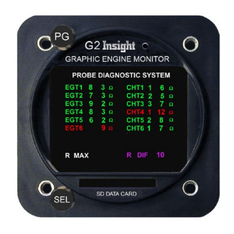
PROBE DIAGNOSTIC - Screen .................................................................................................. 30
PERIODIC TEMPERATURE - Variation Screen .......................................................................... 31
VIBRATION SPECTRUM - Engine Vibration Screen .............................................................. 31-32
TAKE-OFF PERFORMANCE - Take-off Screen .......................................................................... 33
2-AXIS G-LOAD - Turbulence Screen ......................................................................................... 33
LIVE DYNAMIC G-Force Screen ................................................................................................ 34
THEORETICAL - Horsepower Screen ......................................................................................... 35
AUTO RANGE - Capability On The User Configuration Screen .......................................................... 36-37
Using the knobs to navigate the G3-4: .......................................................................................... 37
Setting up the G3-4 Temperature Bargraph Display: .................................................................... 37
Using the Auto Range function (Method 1): ................................................................................. 37
To save the results of auto ranging: ............................................................................................. 37
Setting up the G3-4 Temperature Bargraph display manually (Method 2): ................................... 37
AUTORANGE INFLECTION and EGT MAX TEMPERATURE explained: ............................. 37-38
EGT Smoothing: ............................................................................................................................38
Adjusting the bar heights from the main screen (Method 3): ....................................................... 38
FUEL FUNCTION - Screens ................................................................................................................ 39-40
ADJUST K-FACTOR - On G3-4 ................................................................................................... 40
SETUP GARMIN 400/500 For Fuel Display: ............................................................................... 40
CONFIGURING - Engine Fuel System ...................................................................................... 41
Using the knobs to navigate the G3-4: .......................................................................................... 41
Configuring the Fuel System Type: .............................................................................................. 42
DATA-LOGGING .................................................................................................................................. 43-44
MARK AN EVENT ........................................................................................................................ 43
Introduction to Data-Logging ........................................................................................................ 44
Flight File Open In Excel .............................................................................................................. 44

G SERIES PILOT’S GUIDE .
INSIGHT INSTRUMENT CORPORATION BOX 122, FORT ERIE, ONTARIO, L2A 5M6
4
Warranty and Service
The Insight Instrument Corporation 610C Graphic Engine Monitor system (G3-4) is warranted against
defects in materials and workmanship for two years and 3 years for G4 from date of purchase.
Insight temperature probes are warranted for one year or 1000 hours which ever comes first.
Insight will at its option repair or replace without charge those products that it finds defective.
Insight will not be responsible for repairs required by improper installation, unauthorized maintenance
or abuse.
No other warranty is expressed or implied. Insight is not liable for consequential damages.
Technical Support
If you have difficulty installing or using a GSeries system, please
read the documentation.
Every GSeries system is shipped with complete instructions for
installation and use.
The answers to many technical questions can be found in this
booklet, or the GSeries Installation Manual.
Insight provides customer support free of charge for as long as
you own the instrument.
If you have any questions concerning GSeries operation do not
hesitate to call.
The Customer Service department accepts calls Monday through
Friday between 9 am and 5 pm EST. Be sure to have your in-
strument model number and serial number(s) ready when you
call.
Insight Start Splash Screen
G Series Pages & Functions
Turned On:
G1-2-3-4 YES Main Screen
G2-3-4 YES Lean of Peak Screen
G2-3-4 YES Rich of Peak Screen
G1 YES Lean Screen (Basic)
G1-2-3-4 YES Probe Diagnostic Screen
G3-4 YES Temperature Variation Screen
G3-4 YES Vibration Analysis Screen
G3-4 YES Take-Off G Force Screen
G3-4 YES Two Axis Turbulance Screen
G3-4 YES Live Dynamic G-Force Screen
G3-4 YES Last Triggered Snapshot Screen
G3-4 YES Theoretical Horsepower Screen
G3-4 YES TAS-1000 Air Data Screen
G2-3-4 YES User Configuration Screen
G2-3-4 YES Fuel Onboard Screen
Insight Start Splash Screen

G SERIES PILOT’S GUIDE .
INSIGHT INSTRUMENT CORPORATION BOX 122, FORT ERIE, ONTARIO, L2A 5M6
5
Guide To The G Series Screens
The instrument has two control knobs that operate combination rotary and push button switches.
The top knob in general controls screen selection while the bottom knob controls items within the given screen.
Each screen assigns its own functional needs to the controls that may change depending on context.
A screen may also label the controls with guidance information like “Push to exit”.
Some of the many revolutionary new features of the G3-4 system include:
Engine vibration measurement and analysis.
Specific functionality for safe Lean of Peak operation with no detonation
Oil Temperature and Pressure
Manifold Pressure, Fuel Flow and RPM
OAT
Carburetor and Alternator Temperature
Buss Voltage
Specialized analysis for propeller balance, turbulence and even landing shock.
Integrates and logs data from G3-4, TAS Air Data and GPS for the complete picture.
SD Card stores all engine, air, winds aloft and fuel data (No more lost data).
Entire aircraft life history directly on SD card in PC compatible form.
NOTE:
To check brightness use incandescent light source to shine on GSeries instrument face.
LED and fluorescent will not work because of the lack of infrared in beam.

G SERIES PILOT’S GUIDE .
INSIGHT INSTRUMENT CORPORATION BOX 122, FORT ERIE, ONTARIO, L2A 5M6
6

G SERIES PILOT’S GUIDE .
INSIGHT INSTRUMENT CORPORATION BOX 122, FORT ERIE, ONTARIO, L2A 5M6
7
G1 Color Graphic Engine Monitor

G SERIES PILOT’S GUIDE .
INSIGHT INSTRUMENT CORPORATION BOX 122, FORT ERIE, ONTARIO, L2A 5M6
8
G1 Screens In Order
1 - Main Screen
3 - Probe Diagnostic Screen
2 - Lean Screen

G SERIES PILOT’S GUIDE .
INSIGHT INSTRUMENT CORPORATION BOX 122, FORT ERIE, ONTARIO, L2A 5M6
9
G2 Color Graphic Engine Monitor

G SERIES PILOT’S GUIDE .
INSIGHT INSTRUMENT CORPORATION BOX 122, FORT ERIE, ONTARIO, L2A 5M6
10
G2 Screens In Order
1 - Main Screen
3 - Probe Diagnostic Screen
2 - Lean Screen
4 - User Configuration Screen
5 - Enter Total Fuel Screen
(Defaults to fuel function screen when total fuel is set)
6 - Fuel Function Screen

G SERIES PILOT’S GUIDE .
INSIGHT INSTRUMENT CORPORATION BOX 122, FORT ERIE, ONTARIO, L2A 5M6
11
G3 Series Introduction
Insight’s 610C Graphic Engine Monitor (G3) colour-coded bar graph and digital values may be Primary for EGT, CHT and
TIT.
All other data shown in cyan at the top of display are to be supplementary.
Traditional multi-cylinder exhaust gas and cylinder head temperature systems that force the pilot to switch or scan an indica-
tor from cylinder to cylinder in search of critical engine data, are long obsolete.
Using the latest computer technology, the G3 presents a clear, concise, graphic picture of all engine temperatures simulta-
neously for interpretation at a glance.
Never before has so much engine diagnostic information been available to the pilot and never before, has the pilot been
able to control mixture with such ease and precision for peak fuel efficiency.
Insight’s latest G3 automatically records flight temperature and will also interface with other data sources and report infor-
mation to other instruments like MFD’s. The data-log files stored on the SD card can be easily retrieved by the pilot, in-flight
or post-flight, for instant viewing or permanent record-keeping.

G SERIES PILOT’S GUIDE .
INSIGHT INSTRUMENT CORPORATION BOX 122, FORT ERIE, ONTARIO, L2A 5M6
12
G3 and G4 Screens In Order
1 - Main Screen 2 - Probe Diagnostic Screen 3 - EGT Periodic Temperature
Variation Screen
4 - Engine Vibration Screen
5 - Take-Off Performance Screen 6 - Turbulence Screen 7 - Theoretical Horsepower Screen
11 - User Configuration Screen
(Defaults to fuel function screen
when total fuel is set)
13 - Fuel Function Screen
9 - Dynamic G-Force Screen 10 - Dynamic Snapshot Screen
8 - Air Data Screen
12 - Enter Total Fuel Screen
A G4 single is exactly the same as a G3 only with a bigger display and different knob locations!

G SERIES PILOT’S GUIDE .
INSIGHT INSTRUMENT CORPORATION BOX 122, FORT ERIE, ONTARIO, L2A 5M6
13
Insight Instrument Corporation has developed a slightly bigger derivative of the G3 called the G4.
This derivate, P/N 1200C-001, designated as G4 model, will replace Insight’s earlier twin-engine GEMINI 1200
instruments. The G4 can be configured as a single (G4-001) or twin-engine (G4-002) instrument. Its function list
matches the approved model G3 functions.
The G4 single/twin-engine display functionality is possible by using a slightly bigger LCD and housing.
The G4 utilizes the same technology for housing, bezel, circuit boards, connectors, display and electronic components
(including circuit protection devices) as the already approved G3. Its PCB is populated slightly more to accommodate
additional temperature sensors.
The G3 software was designed so that it can be configured for either single or twin-engine installations.
Therefore, the G4 software is unchanged. The only minor modification was required for a different LCD driver.
The G4 environmental qualification consisted of a subset of DO-160 testing (Temperature/Altitude, Temperature Variation,
Vibration), as most of the G3 test results are applicable to G4 by similarity.
G4 Series Introduction
NOTE: All pages and function on G4 are the same as G3

G SERIES PILOT’S GUIDE .
INSIGHT INSTRUMENT CORPORATION BOX 122, FORT ERIE, ONTARIO, L2A 5M6
14
G4 Twin Engine
The Insight GEM G4-Twin instrument is shown below. The GEM G4-Twin displays a twin-engine airplane’s Exhaust Gas
Temperature (EGT), Cylinder Head Temperature (CHT) and Turbine Inlet Temperature (TIT), Carburetor Temperature
(CARB), Manifold Pressure (MAP), Tachometer (RPM), Oil Pressure (OIL), Fuel Flow (GPH), Bus Voltage (VDC) and
Outside Air Temperature (OAT) on a Liquid Crystal Display (LCD).
Each engine may be temporarily displayed similar to the G4-Single display by turning the page knob (PG) to the left or
right accordingly for leaning or engine diagnostic purposes.
The Insight Graphic Engine Monitor GEM 1200C (G4) Twin is capable of displaying the airplane’s engine Exhaust Gas
Temperature (EGT), Cylinder Head Temperature (CHT) and Turbine Inlet Temperature (TIT), Carburetor Temperature
(CARB), Manifold Pressure (MAP), Tachometer (RPM), Oil Pressure (OIL), Fuel Flow (GPH), Bus Voltage (VDC) and
Outside Air Temperature (OAT) on a Liquid Crystal Display (LCD).
The G4 unit can be configured and installed as a single-engine (G4-001.) or twin-engine (G4-002) instrument.
The GEM G4-Single and GEM G4-Twin indicate temperatures that are displayed to one degree resolution in Fahrenheit
or Celsius degrees. The temperature unit is displayed in the lower portion of the display. The LCD dims automatically with
the intensity of ambient light.
The white, green and red colour-coded bar graph and digital values in the central and lower part of the display may be
used as primary indicators for EGT, CHT, and TIT. The cyan colour-coded values at the top of the display are supplemen-
tary, for reference only.

G SERIES PILOT’S GUIDE .
INSIGHT INSTRUMENT CORPORATION BOX 122, FORT ERIE, ONTARIO, L2A 5M6
15
The EGT values are displayed as vertical white bar graphs (one per cylinder). Digital EGT values for each cylinder may
be indicated by white four-digit numeric displays below the bar graph. CHT is indicated by a vertical green bar graph (one
per cylinder) while the CHT value is within normal CHT operating range, or by a red vertical bar graph if the CH [value
exceeds the maximum CHT limit. A horizontal red line indicates the maximum allowable CHT. Digital CHT values are
indicated by 3-digit numeric displays below the bar graphs. The digital CHT values are show in green while within normal
operating range or red if the CHT limit is exceeded. Turbine Inlet Temperature (of a turbocharger-equipped engine) is
displayed by a green vertical bar graph and digital value on the right-hand side of the display while the TIT value is within
normal operating range, or by a red bar graph and digital display if the TIT value exceeds the maximum TIT limit. A red
horizontal line displays the maximum allowable TIT.
The GEM G4 instrument senses temperatures through thermocouple-type probes. The instrument is powered typically
from the avionics bus and protected by a dedicated, trip-free, resettabte 1A circuit breaker. GEM instruments automatically
accommodate both 14 and 28 VDC electrical systems.
LIMITATIONS
The Insight Engine Monitor GEM 1200C – G4-Single and G4-Twin instruments may replace any eligible aircraft Cylin-
der Head Temperature (CHT) indicator or Exhaust Gas Temperature (EGT) or Turbine Inlet Temperature (TIT) indicator.
Single-engine airplanes utilize the G4-Single instrument, while twin-engine airplanes utilize the G4-Twin.
The Manifold Pressure (MAP), Carburetor Temperature (CARB), Tachometer (RPM), Oil Pressure(01l), Fuel Flow (GPH),
Bus Voltage (VDC) and Outside Air Temperature (OAT) indications at the top of the display are supplementary information,
for reference only.

G SERIES PILOT’S GUIDE .
INSIGHT INSTRUMENT CORPORATION BOX 122, FORT ERIE, ONTARIO, L2A 5M6
16
G4 Twin Screens In Order PG 1
1- Twin engine page
From any page push and hold SEL
knob to return to Twin page
2- Turn SEL to right for right engine
Tap SEL to clear lean boxes
3- Turn SEL to left for left engine
Tap SEL to clear lean boxes
4- Left engine probe page 5- Right engine probe page 6- EGT Variation page
Turn SEL knob to view all cylinders on
right and left engine
7- Vibration spectrum page
PUSH SEL knob to view all vibration
pages on right and left engine
There are 6 screens per engine to
examine, each of the primary axis (x,
y and z) and an averaged version of
each.
8- Takeoff G Force page 9- Turbulence G Force page

G SERIES PILOT’S GUIDE .
INSIGHT INSTRUMENT CORPORATION BOX 122, FORT ERIE, ONTARIO, L2A 5M6
17
G4 Twin Screens In Order PG 2
10- Hard landing G Force page 11- Hard landing graph page
12- Horsepower page
13- Air Data interface page 14- User configuration page
15- Set fuel page 15- Fuel page

G SERIES PILOT’S GUIDE .
INSIGHT INSTRUMENT CORPORATION BOX 122, FORT ERIE, ONTARIO, L2A 5M6
18
First Flight With The G3-4
Now that the day is finally here for you to fire up your new G3-4 and take it for a flight you are probably eager to explore all
the new functions. Before you take that first flight a few minutes should be invested to check the installation of the instru-
ment. We recommend you read through this section once first before stepping into the cockpit.
With the avionics turned on, the G3-4 will power up and present its title screen. During this period the user may press and
hold the top button to enter configuration mode if desired. Most of the configuration is pre-entered for you at the factory or
by your installer, but you may wish to double-check or adjust these parameters. After the G3-4 is configured cycle the avi-
onics to reboot the instrument into its normal operating mode. After the title screen is displayed for a few seconds the main
temperature bargraph display appears.
Have a look at the voltage reading: it should show the battery voltage of your aircraft. The manifold pressure should indi-
cate the ambient pressure, the OAT should be indicated and the digital numbers at the bottoms of the temperature columns
should show the temperature under the cowling. All other indications should show 0.
Start the engine and allow it to idle. The RPM, fuel flow, oil pressure, and manifold pressure indications should come to life
and match the ships gauges. The voltage indicator will now be showing an increase in voltage owed to the charging system.
The digital temperature indications will immediately begin to increase, although it will take a little while for the CHT bars
to climb due to the thermal mass of the cylinders. Likewise, EGT columns may not appear until the throttle is advanced to
fast-idle.
If you want you can turn to the Fuel Onboard screen and tell the G3-4 how much fuel is onboard. After you do be sure to
select Save and Exit at the bottom of the screen. This will allow you to observe the Fuel Totalizing functions. Return to the
main temperature bargraph screen before proceeding.
If all looks well prepare to do your run-up. The G3-4 comes from the factory already set up and ready to go right out of the
box. We have preset the EGT bar heights to accommodate a range of EGT temperatures that is appropriate for an average
user’s engine. But what if you have a turbo-boosted engine that runs hotter than average, or you were forced by mechanical
clearances to put the EGT probes further down the exhaust tubes than you would have liked which leads to lower reported
EGT readings? The factory settings for EGT heights may then be inappropriate for your airplane.
It’s no problem for the versatile G3-4. A few quick clicks and turns of the bottom knob on your first flight will allow you to tailor
the height of the EGT columns to the actual temperatures reported by the probes. The G3-4 can even do the job automati-
cally by using the “Auto-range” functionality. Refer to the Section on “Adjusting EGT bar height” for details on how to adjust
the columns.
After taking off and reaching cruise altitude you will get your first opportunity to try the special lean mode functions. The new
lean mode is easier than ever to use and tells you exactly how far the EGT’s have dropped since they peaked, whether you
are on the rich or lean side of peak, and what the fuel flow was during the peak. To reset the lean mode and start again just
press and hold the bottom button. Remember to always begin well rich of peak EGT or you will not get a true indication of
where peak is. A more complete description of the leaning process may be found in the “Description of Main Screen” section
of this document.
Flip through the various pages of information available using the top knob. Observe your 2-Axis Turbulence measurements,
your Theoretical Horsepower (which also shows your Oil Temperature and Oil Pressure), and your Fuel Totalizing screen.
This will give you an idea what the G3-4 can do for you once you are more familiar with it. The Probe Diagnositics screen
is always available to help keep tabs on the health of your temperature probes. Refer to the various discussions of the indi-
vidual screens throughout this document for more in-depth information.
It’s easy to get overwhelmed by the wealth of information available to you, but don’t forget it is all being recorded on the SD
Card for later review, so you don’t have to learn everything all at once. In addition, at any time you can press and hold the
top knob to place a bookmark on your log file. These bookmarks, sorted numerically, will allow you quickly scan your log
file and go directly to the point in the log you were interested in when you placed it. It’s a valuable tool that you can use as
often as you like.

G SERIES PILOT’S GUIDE .
INSIGHT INSTRUMENT CORPORATION BOX 122, FORT ERIE, ONTARIO, L2A 5M6
19
After you have returned to the airport and shut down after your first G3-4 test flight, we recommend you remove the SD Card
and examine the data log using your favorite spreadsheet program. If you didn’t get a chance to set your EGT bar heights
as discussed earlier, you will get a good idea where it should be set for next time by looking at the EGT columns.
Using G3-4 On The Ground
The temperature range of the G3-4 extends lower than most traditional EGT systems to include temperatures normally en-
countered at start-up. Under normal engine operation at 1,000 to 1,200 rpm, the G3 will produce a white bar EGT indication
for each cylinder. The precise indication will vary from one installation to another, and it is not unusual to observe fairly large
EGT differentials between cylinders at idle or taxi power settings.
One very useful feature of the G3-4 is its ability to detect abnormal combustion during the pre-take-off run-up.
The primary purpose of the pre-take-off engine run-up is to verify the airworthiness of the engine’s ignition system, plus
carburetor heat and propeller control. Pilots without extensive engine instrumentation are accustomed to detecting engine
and/ or ignition problems by an rpm drop or roughness during the run-up.
With the G3-4 a much more accurate diagnosis of problems is possible.
As you run your engine up to 1,700 or 1,800 rpm (or as recommended in your aircraft’s Pilot’s Operating Handbook), you will
observe a rise in EGT for all cylinders, to about one third of full scale. Normally, these indications will vary somewhat from
cylinder to cylinder. The G3-4 should be carefully observed during the magneto check.
Combustion is initiated by two spark plugs firing simultaneously in each cylinder.
Under single mag operation, only one plug is firing, producing only one flame front in the combustion chamber, resulting in
a slower, more prolonged combustion.
This places the point of peak combustion pressure later in the power stroke and the tachometer will register a drop of 50 to
150 rpm. Since the exhaust gases have less time to cool before being expelled from the cylinder, the exhaust gas tempera-
tures of all cylinders should rise. (50 to 100° F).
Various problems can be detected easily during run-up with the aid of the G3-4. The absence of an rpm drop or EGT rise on
single-mag operation indicates trouble in the form of a hot mag or defective ignition switch.
A more common indication of trouble is the total disappearance of an EGT indication for one or more cylinders after switch-
ing to single-mag operation, indicating a faulty ignition wire or spark plug. If the affected cylinder returns to a normal EGT
indication when operating on the other magneto, you have isolated the problem to a single spark plug (or lead) in a single
cylinder.
In the absence of adequate engine instrumentation, the initial diagnosis of fouled spark plugs is usually made on the basis of
a greater rpm drop for one mag than the other. Manufacturers’ handbooks generally warn the pilot to regard any difference
of more than 50 rpm between mags as suspicious. But it is important to note that an rpm drop will register only if more plugs
are fouling on one mag than on the other. If each magneto harness harbors one bad plug or lead this would cause a uniform
mag drop and the double fault would go completely undetected. On the other hand, an entirely different malfunction such as
a partially plugged injector could create the same symptoms.
Careful analysis of G3-4 data can help a pilot determine the precise cause of mag drop, or pinpoint problems hidden behind
a uniform mag drop. In both cases cited above, the G3-4 would indicate higher EGTs for the affected cylinders.
Run-up is also a good time to check carburetor heat (if present) and mixture control. Application of carburetor heat causes
a reduction in the density (and therefore oxygen content by volume) of air coming into the engine, inducing an over-rich
condition. This is indicated by a noticeable drop in engine rpm and exhaust gas temperature.
If the application of the carburetor heat control fails to produce these effects, it is likely that the carb heat control is mis-
rigged, causing the airbox flapper valve to hang open and allowing hot air to leak into the carburetor on a full-time basis.
This should be remedied as soon as possible.

G SERIES PILOT’S GUIDE .
INSIGHT INSTRUMENT CORPORATION BOX 122, FORT ERIE, ONTARIO, L2A 5M6
20
During the mixture check, a uniform rise of EGT indications for all cylinders will confirm that the mixture control is functioning
correctly. The amount of temperature rise will depend on the degree of mixture control movement.
Each cylinder should show a rise in EGT upon leaning. Failure of a cylinder to show a significant rise, or an abnormally large
EGT differential between cylinders in fuel injected engines, may indicate a fuel injector nozzle constriction.
In many engines, a large inter-cylinder EGT spread is normal at low power settings (even with fuel injection) so a diagnosis
of this type is impractical until the pilot becomes thoroughly familiar with the normal indications for his or her engine.
Even so, this type of diagnosis, easily made with the G3, is virtually impossible with other EGT systems.
Using G3-4 On Take-off
The G3-4 can be used during takeoff to identify a very serious class of combustion problems that can result from poor fuel
distribution at take-off power settings.
The combustion phenomenon known as pre-ignition can do extensive damage in a matter of a few seconds if left unat-
tended. This combustion process produces abnormally high temperatures in the combustion chamber which results in im-
mediate full-scale EGT indications followed by a rise in cylinder head temperatures.
Should this type of indication occur during the takeoff roll, the takeoff should be aborted.
If takeoff has proceeded beyond the point of no return, power should be reduced immediately (maintaining flight) and the
mixture enriched if possible to make the temperature drop in the affected cylinder(s).
A precautionary landing should be made as soon feasible.
Pre-ignition can be caused by red-hot cylinder deposits or overheated exhaust valves.
Regardless of cause, pre-ignition, once started, causes an extreme temperature rise in the combustion chamber and is self-
sustaining until engine failure occurs (often in a few seconds).
Broken connecting rods, melted pistons, and cylinder head separation are among the common pre-ignition induced failures.
A second type of pre-ignition that does not fit the previous definition is magneto induced pre-ignition.
It results from extreme timing errors in magneto adjustment or failure of the magneto itself.
Detonation in automobiles is commonly referred to as ping or knock. It is an unusually rapid form of combustion that follows
ignition induced combustion and is caused by high compression, high temperatures and a lean mixture.
The rapid combustion of detonation is significantly advanced by the time the exhaust valve opens and the temperature
encountered by the EGT probe is lower than normal. Detonation results in higher peak combustion temperatures and pres-
sures which translate into higher CHT’s and lower EGT’s. More importantly, detonation imposes significantly greater stress
on the engine components than normal operation. It may be caused by excessively lean operation at high power settings
because of fuel system malfunctions, injector nozzle constrictions, improper mixture control settings, insufficient fuel octane
or avgas contaminated by jet fuel.
Leaning for Take-off
Leaning normally aspirated engines for takeoff is advisable for best performance under high density altitude conditions and
this is something that can be done with confidence and accuracy with the G3-4.
Remember that the full-throttle, full rich-mixture setting is designed to provide an enriched fuel flow for proper engine cooling
during takeoff at sea level on a standard day.
This over-richness is a FAA-mandated minimum of 12% above the worst case detonation-onset fuel flow.
With increasing density altitude, this over-richness robs your engine of power. Leaning on a high altitude takeoff can restore
a significant amount of power and add measurably to aircraft performance. Consult the Pilot’s Operating Handbook for the
airplane manufacturer’s recommended high altitude takeoff procedures. On some aircraft equipped with fuel flow gauges,
the full-power altitude reference marks indicate acceptable fuel flows for various altitudes (typical reference marks are S.L.,
3000, 5000, 7000).
Sometimes a specific temperature (eg. 150° F rich of peak EGT) is specified as the takeoff power mixture guideline.
After some experience with the G3-4 to determine the location of peak EGT, the G3 can be used to set the mixture using this
guideline, or (with careful operator technique) to produce the EGT indications similar to a normal sea level takeoff.
This manual suits for next models
5
Table of contents
Other INSIGHT Measuring Instrument manuals
Popular Measuring Instrument manuals by other brands

Skil
Skil LL0516 Original instructions

ThermoWorks
ThermoWorks ThermaQ 2 operating instructions
THORLABS
THORLABS PDA100A user guide

PCB Piezotronics
PCB Piezotronics IMI SENSORS 622B61 Installation and operating manual

SevenStar
SevenStar D08-8C instruction manual

IA Networks Technology
IA Networks Technology IPM3400 user guide
