INSTROTECH 4001 User manual

Universal Process /
Counter / Frequency /
Integrator / Totaliser
Indicator
Operating Manual for Models :
4001 / 4011 / 5001 / 5011 / 5600 /
8001 / 5001-T / 8001-T

Cleaning
Do not clean the instrument while the instrument is on.
Harsh abrasives, solvents, scouring cleaners and alkaline
cleaning solutions, such as washing soda, should not be
used especially on the display window. The outside of the
instrument may be wiped down with a slightly damp clean
cloth (lightly moistened with water only).
Under no circumstances should you attempt to wipe the
inside of the instrument.
Safety
This equipment is supplied by a mains voltage which can
cause an electric shock injury. Before removing the circuit
board from its housing, switch the instrument off, isolate it
from the mains power supply and make sure that it cannot
be connected inadvertently by other persons.
If the circuit board is removed from its housing, do not
apply power to the instrument unless specifically instructed
to do so in these instructions. When working on live
equipment, exercise great care, use insulated tools and test
equipment, and do not work alone.
When fitting option boards, always put the circuit boards
back in the housing with the back-plate securely fastened
before powering up the instrument.
When handling circuit boards, ensure that full anti-static
precautions are observed.
Replace external mains fuse with one of an equivalent type.
Contents
Introduction ....................................................................... Page 3
Electrical specifications ..................................................... Page 3
Input ranges ...................................................................... Page 3
Sensor excitation................................................................Page 3
Power supply .....................................................................Page 4
Programmable specifications ............................................ Page 4
Other specifications ...........................................................Page 4
Installation (panel cutout) .................................................. Page 5
Installation (fastening) ....................................................... Page 5
Display & keypad (during normal display mode) ...............Page 5
Display & keypad (during programming mode) .................Page 5
Connections & links ...........................................................Page 6
Process inputs ..............................................................Page 6
Frequency / count inputs ..............................................Page 6
Hardware link selection for J5 ...................................... Page 6
Potentiometer input ......................................................Page 7
Option connections & links, Power supply links ........... Page 7
Programming chart ............................................................Page 8
Display codes explained ................................................... Page 10
Programming example ...................................................... Page 11
Asciibus protocol ............................................................... Page 12
Setting up Model 5001-T totaliser / integrator ................... Page 13
Option 3000, 3001-P / M, 3002, 3003, 3004-P / M ........... Page 15
Option 3006,3008,3009,3010,3011,3012, 3013.................Page 16
Option 3014, 3017-P / M, 3018-P / M.................................Page 17
Option 3021, 3022, 3023, 3024..........................................Page 18
Option 3025, 3026, 3028 ...................................................Page 19
Diagram “P” .......................................................................Page 20
Diagram “M” ...................................................................... Page 20
Declaration of conformity .................................................. Page 20
Guarantee ......................................................................... Page 20
Page 2

0 - 20 mA, 4 - 20 mA, 0 - 200mV, 0 - 2 V, 0 - 10 V, 0 - 20 V, Special
(pot input), 0.2Hz - 40kHz (24V max, up to 0.01 Hz resolution).
Electrical Specifications
Sensor Excitation
Accuracy & linearity : 0.05% of F.S., or 1 count
Option 3011/15/27 accuracy : 0.5% of F.S., or 1 count
Internal resolution : 20000 counts (bi-polar)
Temperature coefficient : 20 ppm / °C typical
Settling time for process inputs : 0.5 seconds
Settling time for frequency input : 5 milliseconds (with no filter)
Operating temperature range : -10 to +50°C
Storage temperature range: -40 to +80°C
Humidity : < 85% non-condensing
Warm-up time : None required
Electro-mechanical relays : 250V AC, 30V DC, 2A, PF=1
Solid state relays : 400 V AC/DC, 0.5A, PF=1
Analogue output accuracy : 0.1% of full scale, 12 bits
Current analogue output load : 500 Wmaximum
Voltage analogue output load : 1 kWminimum
Memory retention : Full non-volatile operation
Option 3006 isolation rating : 1500 V
Declaration of conformity : See last page
24V DC: (17-26V), current limited. For 2-wire transmitters,
proximity switches or encoders. With option 3010,
current capability increases to 100mA
5V DC: ± 1%, maximum 25mA
2.5V DC: Precision reference, 2mA max for pot (2 kWmin)
Input Ranges
The Models 4001, 4011, 5001, 5011, 5600, 8001, 5001-T, 8001-T
indicators are universal LED process indicators that can be
applied to most process variables with analog & digital inputs.
These high accuracy panel meters are designed for accurate
measurement & display of pressure, level, flow, freq, up & down
counting, DC voltages or currents & revolutions / min. Selected
models offer integration / totalisation of the input signal. The built-
in sensor excitation supply is link selectable for 2-wire / 3-wire
transmitters, encoders & potentiometer input.
Model 4001 is a 4 digit (-1999 to 9999) indicator offering process
inputs of type mA, mV, V, pot and frequency.
Model 5001 is a 5 ½ digit (-199999 to 199999) indicator offering all
the features of Model 4001 but with process x frequency functions
as well as count rate & totaliser.
Model 5600 is a 6 digit (-199999 to 999999) indicator offering all
the features of Model 5001. Set points and other options are
however limits to 5 ½ digits.
Model 5001-T is a 5 ½ digit (-199999 to 199999) indicator offering
all the features of Model 5001 but with process integration /
totalisation included.
Model 8001 is a 5 ½ digit rate display indicator with an 8 digit count
display, while the Model 8001-T has process integration /
totalisation included.
Model 4011 & Model 5011 offer Asciibus serial input for remote
display of serial information.
Introduction
Page 3

Programmable Specifications
5½ / 6 / 8 Digit Models
Zero & full scale setting : -199999 to 199999
Decimal point : Adjustable on all digits
Process filtering : 0.0 to 10.0 seconds
Freq / counter scaler : 0.05 to 1999.99
Frequency units : Selectable Hz or RPM
Frequency filtering : None, 0.5, 1.1 or 4.5 seconds
Counter features : Reset (count up) / Preset (count down),
: Counter rate & totaliser
Options :
Analog output zero & span : -199999 to 199999
Alarm setpoint values : -199999 to 199999
Alarm hysteresis : 0 to 255 (default 1)
Alarm delay : 0 to 255 seconds (default 0)
Alarm relay settings : Selectable HIGH or LOW alarm
Alarm relay state : Selectable NO or NC
Unit address : 0 to 99
Baud rate : 2400, 4800, 9600, 19200
Standard
115 / 230 VAC ± 10%, link selectable, 50/60Hz, 5VAtyp
Optional
8 - 30VDC isolated power supply (Option 3008), 5VA typ
8 - 30VDC non-isolated, 5VA typ
95V-265V AC/DC isolated power supply (Option 3010), 5VA typ
Power Supply
4 Digit Models
Zero & full scale setting : -1999 to 9999
Decimal point : Adjustable on all digits
Freq / counter scaler : 00.01 to 99.99
Frequency units : Selectable Hz or RPM
Frequency filtering : None, 0.5, 1.1 or 4.5 seconds
Counter features : Reset (count up) / Preset (count down)
Options :
Analog output zero & span : -1999 to 9999
Alarm setpoint values : -1999 to 9999
Alarm hysteresis : 0 to 255 (default 1)
Alarm delay : 0 to 255 seconds (default 0)
Alarm relay settings : Selectable HIGH or LOW alarm
Alarm relay state : Selectable NO or NC
Unit address : 0 to 99
Baud rate : 2400, 4800, 9600, 19200
Other Specifications
DIN 48 x 96 housing, 147mm depth
Industrial strength single piece housing
Housing is flame retardant ABS plastic that meets UL94 V-0
Circuit board is flame retardant material that meets UL94 V-0
Front facia rating : IP65 (with o-ring seal supplied as standard)
Page 4

Fastening
The supplied fastening
clips may be fitted on
the side or the top /
bottom of the housing.
Ensure that the clip &
screw is mounted as
shown here.
Caution : Do not
overtighen the screws.
Min
12
45
92
Installation
To gain access to the
circuit boards, switch
power off and remove
terminals from the
back of the housing.
Observe safety
precautions. Use a
screwdriver to clip the
back-plate off.
During programming mode Display & Keypad
147
Panel Cutout
Installation
48
96
Enter
Programming menu
Move to next digit
Increment digit / change selection
Total
LED
(display
shows
totalised
value)
48
96
2341
Reset peak value (option 3012 only) /
Auto-zero (option 3014 only)
Print on demand (comms option only)
Show normal value (option 3012 only)
Show peak / valley hold value
(option 3012 only)
2341
kPa
All dimensions in mm
During normal display mode Display & Keypad
Page 5
Min
12
DIN 1/8 cutout
O-ring sealing
gasket supplied
as standard
Rate LED
(display shows rate)
Alarm LEDs
(illuminated whenever
relays are energised)

Hardware Link Selection For J5
mA XX
X
200 mV
2 V
10 V
20 V
Special*
X
X
X
X
X
Analog Output
+5VDC X
+24VDC, current limited X
+2.5V Vref X
X
Terminal 3 Voltage Output
0 - 20 / 4 - 20mA (option)
0 - 10V (option)
X
Input
J5
S
+
-
+
-
L
N
Namur
Circuit board
Frequency:
Display Hold (Option 3026)
Potential free contact
Namur
PNP / Volts
J8
P
CCounts /
Process
input
selector
1. In Lo
3. + Vout
4. Dig In
2. In Hi
J7
J5
NPN
Select sensor type
Connections & Links
Excitation select:
NPN / PNP
Generated frequency
(24V maximum)
2-wire NAMUR sensor
(must work with
5V excitation)
Line / mains frequency
measurement option
(Option 3021)
3-wire proximity switch /
encoder (NPN or PNP type)
Counter : Reset
Circuit board
True RMS AC (Option 3005)
Ohm / Tap input (Option 3011)
Process inputs of type
200mV, 2V, 10V, 20V,
0/4-20mA. (Select J5 link !)
+
-
Namur
PNP / Volts
J8
P
C
Counts /
Process
input
selector
1. In Lo
3. + Vout
4. Dig In
2. In Hi
J7
J5
Digital
sensor
selection
NPN
S
+
-
Select input link
(see J5 link table)
Process Inputs
4 - 20 mA, 2-wire
transmitter
0 - 20 mA, 3-wire
transmitter
Freq / Count Inputs
-
+
Totaliser reset OR
Rate vs Total select OR
Reset peak / valley hold (Option 3012) OR
Remote auto-zero (Option 3014) OR
Display hold (Option 3026)
Note : Counter or totaliser reset may also be achieved by pressing the 'Enter' key (press for 3 seconds). External reset is almost instantaneous.
Note : The "special" (SP) input is normally configured for potentiometer input. It can however be configured to order as per customer's requirements.
Note : For 2- wire NAMUR sensors, the proximity switch must be able to operate from 5V supply.
Place hardware links as shown in the diagrams.
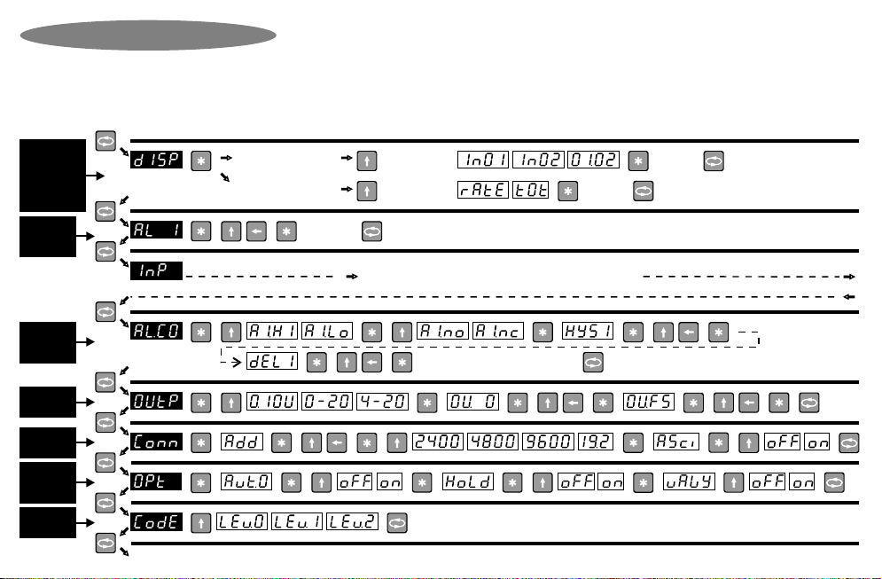
Remember : Configuring this instrument requires two steps. (1)
Select the correct hardware links as shown. (2) Program the
instrument with the programming chart on page 8 & 9.
Page 6

For 230V
operation
For 115V
operation
DC supply
AC supply
-
+
NL
J2
Neut (+)
Power
supply
selector
Live (-)
*** External 0.5A fuse recommended ***
AC supply
-
+
NL
J2
Neut (+)
Power
supply
selector
Live (-)
DC supply
Power Supply Links
S
+
-
Circuit board
Display hold (Option 3026)
Potentiometer input
(Link as shown)
Namur
PNP / Volts
J8
P
C
Counts /
Process
input
selector
1. In Lo
3. + Vout
4. Dig In
2. In Hi
J7
J5
Digital
sensor
selection
NPN
Link as shown
Analogue
output
option
(see links
on J5)
RS232/
RS485
option
Alarm 1
Alarm 2
Alarm com
-
+
1. In Lo
3. + Vout
4. Dig In
7. +D (Rx)
5. -An out
2. In Hi
8. -D (Tx)
9. DGND
10
6. +An out
Neut (+)
11
12
Live (-)
Circuit board
J5
Link here for
voltage output
Alarm connections
for 3001/4-P only.
Solid state relays,
400V AC/DC,
0.5 A max, PF=1
Interposing relays
recommended for
heavy duty applications
Pulse output
(Option 3023)
Option Connections & Links
Linked for
current output
Page 7
J2 link positions do not matter for DC supply
or for Option 3008 or Option 3010.
Place hardware links as shown in the diagrams.
Remember : Configuring this instrument requires two steps. (1)
Select the correct hardware links as shown. (2) Program the
Potentiometer Input
RS485 / 232
only (Option
3002 / 3013)
,, ,,,, ,,
,, ,, ,
,, ,, ,, ,, ,, ,,
,
,,
,
,, ,
,
READ ME FIRST !
,
,,
to toggle the
following options
,
to accept
new value
,for menu
to accept
new value,for menu
,
If ‘pro.f’ is chosen in
input menu, then
If ‘d.tot’ or ‘p.int’ is chosen
in input menu, then
,, , , for menu
(Similarly for alarm 2, 3 & 4)
SEE NEXT PAGE for input type selection
“END”. Instrument returns to normal display mode.
to accept
new value
Note 1 : This programming chart is a simplified flowchart for users that have previous experience with this instrument. A programming example is
available in the next few pages to assist new users in understanding this programming chart.
Note 2 : Because this instrument has many options, all possible option menus are shown. Options that are not ordered will not appear in the
programming sequence.
Note 3 : Configuring this instrument requires two steps. (A) Select the correct hardware links (page 6 & 7). (B) Program the instrument with this chart.
Note 4 : To enter programming mode, press the menu key for a few seconds (unless the optional keypad lock has been set). Programming mode timeout
is about 20 seconds. If no key is pressed for 20 seconds during programming, the instrument returns to normal display mode.
, ,, , ,,
Analog output
only (Option
3003 / 3007)
Alarms /
setpoints /
only (Option
3001/4/17/18)
Keypad lock
only
(Option 3025)
START
HERE
Model 5001 /
5001-T / 5600 /
8001 / 8001-T
only, & if ‘pro.f’
or ‘d.tot’ or ‘p.int’
is chosen in
input menu
Programming Chart
(Similarly for alarm 2, 3 & 4)
to toggle the
following options
Alarms /
setpoints /
only (Option
3001/4/17/18)
,,
,,,,, ,,,,,
Auto-zero,
Peak / Valley
hold only
(3012 / 3014)
Page 8

,,
Menu identical
to 'Pro' menu,
followed by :
Special Note :
If Model 4011/
5011 is ordered,
then refer to the
supplemental
page supplied
with this manual.
0.2V, 2V, 10V, 20V, Pot (SP),
0 / 4 - 20mA input selection
Lineariser only
(Option 3000).
Manual setpoint
station only
(Option 3024)
Model 5001 /
5001-T / 5600 /
8001 / 8001-T
only.
See Note
On ‘incr’
Feature
Model 5001 /
5001-T / 5600 /
8001 / 8001-T
only
Model
5001-T / 8001-T
only
Menu identical
to 'Pro' menu,
followed by
'Freq' menu.
Model 5001 /
5001-T / 5600 /
8001 / 8001-T
only
Please Read Me !
This page represents the input configuration
menus, and this chart must be read from top to
bottom. Only program the menu column
corresponding to the operation you require
(for example, for process integration, program
the “P.Int” menu column only. There is no need
to program the “Pro” menu as well.)
Incr Feature
"incr" is for display increment, and
specifies the display increment
steps. e.g. an increment of 10 will
cause the least significant digit to
function as a 'dummy' zero.
Page 9
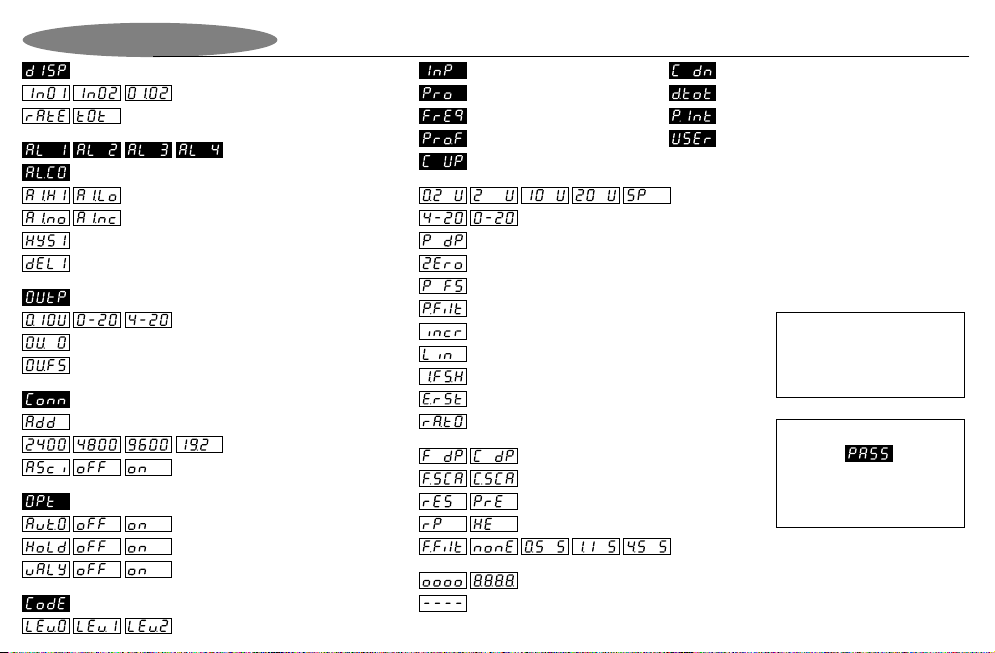
Hardware overrange. Reduce input signal to reduce saturation.
Process input selection (0-20mA, 4-20mA)
Process input selection
(200mV, 2V, 10V, 20V, Special (potentiometer input)
Process decimal point selection (non-floating point)
Process zero display configuration
Process filter - analog inputs (factor 0.0 to 9.9 secs)
Frequency / counter decimal point selection
Frequency / counter scaler (multiplier)
RPM or Hz selection
Filter for frequency input (none, 0.5, 1.1, 4.5 seconds)
Output selection (0-10V, 0-20mA, 4-20mA)
Analogue output menu
Protocol selection. On = AsciiBus. Off =
DigiBus.
Process overscale. Input has exceeded full scale value. / Display test mode.
Display value selection menu
Process, freq, or process x freq input
Rate or totaliser display
Process input
Frequency input
Process x frequency input
Up counter input
Digital input rate & totaliser
Input selection menu
Output zero selection
Output full scale selection
Unit address (default 0)
Counter reset / preset
Display Codes Explained
1st, 2nd, 3rd, 4th setpoint value
Alarm configuration menu (shown for 1st alarm only)
1st alarm setpoint select HIGH / LOW alarm
1st alarm setpoint normally OPEN / CLOSED contact
1st alarm setpoint hysteresis
1st alarm setpoint delay
Communications menu (RS232 / RS485)
Peak OR valley hold. “off” = peak. “on” = valley
Available baud rate values
Process input integration / totaliser
User input for Option 3024 manual setpoint station
Configure digital input as external totaliser reset
Process integration full scale rate hour setting
Display increment. e.g. '10' would give dummy zero.
Configure digital input as external display rate / total selector
Linearisation menu (on/off) select (optional)
Process full scale display configuration
Auto-zero option turned off or on
Down counter input
Please Note :
If the front keypad has been
locked, then the word “PASS” will
appear. See option 3025 for more
information.
Peak / valley hold option turned off or on
Option menu for Auto-zero feature and Peak / Valley Hold feature
Keypad lock security level. Level 0 = none, Level 1 = alarm value changes, Level 2 = full
Keypad lock security menu. See Option 3025 for more information.
Page 10
Please Note :
Display screens shown in black
are to indicate the beginning of
sub-menus.

Remember, the symbols on the keypad have the following
definitions during programming.
Press “Menu” for
3 seconds
Next Menu
Item Increment digit Next Digit Enter /
Accept value
Press “Next digit” to
amend the next digit
Press “Increment digit”
to increase value
Press “Enter” to see
Alarm / Trip 1 value.
Amend the other digits in the same way until the desired trip
value is entered.
The entire programming menu operates in a manner
similar to the example described above.
Press “Menu” to
proceed to next
trip value.
Press “Enter” to accept
Alarm 1 value.
Setting Up Alarm Values (Option)
Programming Example
Use the same menu steps above to change trip levels
for trip 2, 3 and 4.
Page 11

IGNORE THIS PAGE unless communications option has been ordered. When the RS232 (option 3013) or RS485 (option 3002) is
ordered, two protocols are made available, namely ASCIIbus & DIGIbus protocols. DIGIbus is the default protocol which is used for
the calibration and configuration of the instruments, and whenever the instrument is connected to master-slave systems. DIGIbus
protocol is therefore used in complex bus systems, and is NOT described here. Please contact factory for the DIGIbus protocol.
ASCIIbus, which is described here, is much easier to use as it can easily interface to third party systems with very little engineering
work required. It is a purely ASCII based (7 bit) protocol. The protocol is essentially designed for one way communications
(instrument to PC). Under the "Conn" (connection) programming menu, ASCIIbus is enabled by selecting "ASCI" to "ON". If "OFF" is
selected, the DIGIbus protocol will be active. Although designed for one way communications only, the ASCIIbus protocol contains an
address. The address range is "00" to "99".
Using address "00" : If this address is selected, the instrument will only transmit data on demand by either momentarily pressing the
'menu' key, or by transmitting a byte (any ASCII character) to the DPM. This mode is useful for interfacing to printers. In addition, field
' AA ' will contain the ASCII character "blank/space". Field ' P ' will also contain the ASCII character "blank/space".
Using address "01" to "99". If any of these addresses are used, the meter continuously transmits information at approximately 5 times
a second.
The data format string output from the indicator is (7 bit ASCII code is used):
Line Settings : 7 Data Bits, 1 Parity bit, Odd Parity, 1 Stop Bit.
Baud Rate : Selectable 2400, 4800, 9600, 19200.
Data Bits : Numerical ASCII characters : 0, 1, 2, 3, 4, 5, 6, 7, 8, 9
Other ASCII characters : #, blank/space, +, -, CR, LF
Protocol format is : # AA S D D D D D D D D P CR LF
where : # = indicates start of message
: AA = Instrument address. ASCII 00 to 99. 00 is default.
: S = sign (polarity) ( ASCII "+" or "-" ).
: D = data bits (data for 8 numerals). See Note (1).
: P = decimal point position. ASCII 0 to 8.
: CR = ASCII carriage return.
: LF = ASCII line feed.
The output will follow the display reading. This
means that if the peak-hold option has been
ordered and activated, the communications output
will peak-hold as well.
Note 1 : This protocol allows for future expansion.
Therefore if Model 4001 is used for example, the
first four digit data will contain the ASCII character
"blank/space" and the last four digits will contain
the display reading. Similarly, if the Model 5001 is
used for example, the first 2 digit data will contain
the ASCII character "blank/space" and the last six
digits will contain the display reading.
Asciibus Protocol (for Option 3002 / 3013)Communications
Page 12

Page 13
Example 1:
Formula: I.FS.H value without decimal points = (Desired value on display after 1 hour * 14062.5)
-----------------------------------------------------------------------
(Total value accumulated after 1 hour/256)
Example: A 4-20mAinput signal must correspond to a 0-2500 rate display. This input must also be integrated (totalised) over an hour.
The totaliser must show 1250 after 1 hour if the input is 12mA for that hour. For calculation purposes, calculate the totalised value at
20mA, which in this case will be 2500.
According to the above formula,
A = Desired value on display after 1 hour
B = I.FS.H Value without decimal points
C = Total value accumulated after 1 hour (i.e. max value on rate (2500) * 3600 seconds = 9 000 000 )
B = (A * 14062.5)
--------------------
(C/256)
Therefore B = (2500 * 14062.5)
------------------------
(9000000/256)
I.FS.H = 1.000
After 1 hour at 12mA the display should show 1250. After 1 hour at 20mA, the display should show 2500.
Under the P.Int sub-menu in the instrument, set the following: select 4-20; P dP = oooooo; ZEro = 000000; P FS = 002500;
P.Filt = 00.5; incr = 000; C dP = oooooo; I.FS.H = 1.000
How to calculate the I.FS.H (integrated full scale hour) value for Model 5001-TModel 5001-T

Page 14
Example 2:
Formula: I.FS.H value without decimal points = (Desired value on display after 1 hour * 14062.5)
-----------------------------------------------------------------------
(Total value accumulated after 1 hour/256)
Example: A 4-20mAinput signal must corresponds to a 0-100 displayed rate value. The input signal must be totalised over an hour.
The reading at 20mA must be 360 after an hour.
According to the formula:
A = Desired value on display after 1 hour
B = I.FS.H Value without decimal points
C = Total value accumulated after 1 hour (i.e Max value on rate (100) * 3600 seconds = 360 000 )
B = (A * 14062.5 )
-----------------------
(C/256)
Therefore B = ( 360 * 14062.5 )
-------------------------
(360 000/256)
I.FS.H .= 3.600
After 1 hour at 20mA, the display should show 360.
Under the P.Int sub-menu in the instrument, set as follows: select: 4-20; P dP = oooooo; ZEro = 000000; P FS = 000100; P.Filt = 00.5;
incr = 000; C dP = oooooo; I.FS.H = 3.600
How to calculate the I.FS.H (integrated full scale hour) value for Model 5001-TModel 5001-T (cont.)

This option is similar to Option 3001-P but with a single alarm only. See page 7 for connection details. Wire for AL1 only.
This option is similar to Option 3001-M but with a one alarm set point only. See diagram “M” on page 20 for connections. Wire for AL1
only.
See page 7 for connection details.
See page 7 for connection details. Wire for AL1 & AL2 only.
If fitted, this option will accurately linearise signals for flow applications (square root extraction), s-curve (cylinder applications) and
other non-linear signals. The type of linearisation required is specified at time of order and cannot be user selectable. However, the
user has the option of toggling the lineariser feature 'ON' or 'OFF' in the process ('PRo') menu. See page 9 for programming details.
See page 7 for connection details. Select DIGIbus or ASCIIbus protocol from the program menu. See additional protocol documents.
One Set Point (Electro-Mechanical Relay)Option 3004-M
One Set Point (Solid-State Relay)Option 3004-P
0 - 20mA / 4 - 20mA / 0 - 10V Analogue Output OptionOption 3003
RS485 Serial Interface OptionOption 3002
Two Set Point (Electro-Mechanical Relays)Option 3001-M
Two Set Point (Solid-State Relays)Option 3001-P
Lineariser (Square Root / Cylinder / Sphere etc)Option 3000
This option provides two alarm set points with electro-mechanical relays. This option board slots into the upper slot of the panel meter
box. The upper terminals are clearly numbered 13-28 to differentiate them from the lower terminals. Both normally open and normally
closed contacts are provides with each relay. The relays are rated at 250VAC / 30VDC @ 2A. Visual LED alarm indication is provided
on the panel meter front. For connection wiring details, see diagram “M” on page 20. Connect wires for AL1 & AL2 only.
Page 15

Parallel BCD Output OptionOption 3009
This option displays and holds the max or min value (not both) of an input signal. This option is activated in the programming menu
“Opt” by selecting whether “Hold” should be “On” or “Off”, and selecting valley (”valy” = “On”) or peak (”valy” = “Off”) mode.
To show peak / valley value, press the “up” arrow for 3 seconds. To show normal display value, press the “side” arrow key for 3
seconds. To reset the peak / valley hold value, press the “star” key for 3 seconds, or use an external potential free contact (see page
6 for connection details). If analog output option is fitted, the output will hold as well. This option cannot be used with option 3014.
This option provides an 8 - 30VDC galvanically isolated power supply. See page 7 for connection details. This option also provides
excitation of up to four load cells.
This option is supplied as an additional slot in card in the top part of the instrument housing. See additional documentation.
This options allows the instrument to operate from a wide range of AC & DC power supplies. The supply connections are on page 7.
This option measures resistance & tap positions on transformers. See “Process Inputs” diagram on page 6 for connection details.
Peak Or Valley (Max or Min) Hold OptionOption 3012
Ohms / Tap Input OptionOption 3011
95V-265V AC / DC Power Supply OptionOption 3010
This is ordered with option 3002, 3003, 3007 or 3013. It provides a minimum of 1500V isolation between input and output signal.
Wiring connections are different for these isolated options. Use diagram “P” or diagram “M” on page 20 for wiring connections.
Galvanic Isolation (8 - 30V Supply) OptionOption 3008
Isolated Options (Analogue Output / RS232 / RS485)Option 3006
Page 16
See the additional pages supplied for protocol details & page 7 for connection details. Ensure that maximum cable length from
instrument to PC is less than 15 metres.
RS232 Serial Interface OptionOption 3013

Auto-zero OptionOption 3014
Three Set Points (Electro-Mechanical Relays)Option 3017-M
Three Set Points (Solid-State Relays)
Option 3017-P
This option provides three alarm set points with solid state relays. This option board slots into the upper slot of the panel meter box.
The upper terminals are clearly numbered 13-28 to differentiate them from the lower terminals. Only normally open contacts are
provided, which means that should the contacts be closed and the power fails, they will revert to a normally open condition. The
relays are rated at 400V AC /DC @ 0.5A. Visual LED alarm indication is provided on the panel meter front. For connection wiring
details, see diagram “P” on page 20. Connect wires for AL1, AL2 & AL3 only.
This option provides three alarm set points with electro-mechanical relays. This option board slots into the upper slot of the panel
meter box. The upper terminals are clearly numbered 13-28 to differentiate them from the lower terminals. Both normally open and
normally closed contacts are provides with each relay. The relays are rated at 250VAC / 30VDC @ 2A. Visual LED alarm indication is
provided on the panel meter front. For connection wiring details, see diagram “M” on page 20. Connect wires for AL1, AL2 & AL3 only.
This option allows the operator to zero the display at any time and continue the measurement from that zero point. This option is
activated "ON" or "OFF" in the "Opt” menu during programming (see page 8).
During normal operations, pressing the “star key” for 3 seconds will zero the display. The display can also be zeroed via an external
potential free contact (see page 6 for connection details). The display can be zeroed at any time over and over again. If the analog
output option is fitted, the output will follow the display. Note that this option cannot be used in conjunction with option 3012, nor will
this option be available if ‘d.tot’ or ‘p.int’ is selected in the input menu.
Page 17
This option is similar to option 3017-P, but contains four relays (see option 3017-P). For connection wiring details, see diagram “P” on
page 20. Connect wires for AL1, AL2, AL3 & AL4.
Four Set Points (Solid-State Relays)Option 3018-P
This option is similar to option 3017-M, but contains four relays (see option 3017-M). For connection wiring details, see diagram “M”
on page 20. Connect wires for AL1, AL2, AL3 & AL4.
Four Set Points (Electro-Mechanical Relays)Option 3018-M

This option is used with the optional totalising features of selected meters. With this option, the relay of alarm #1 pulses whenever the
totalising display changes by one count (alarm #1 relay will no longer function as an alarm setpoint). The maximum pulse rate is two
pulses per second, and it is therefore critical that the totalising display is configured not to change by more than two counts per
second. See the programming menu page 9 for more information on setting up the totalising parameters.
Pulse Output OptionOption 3023
The vertical bar-graph display option provides a graphic linear representation of the process variable being measured. The bar
graph’s zero and full scale setting is programmed by the ‘Outp’ sub-menu of the programming menu, which also controls the analog
output option. The ‘Out.O’ controls the zero point of the graph, and the ‘Ou.Fs’ controls the full scale value of the graph. See the
programming menu page 8 for more information. The instrument must be mounted vertically.
Vertical Bar Graph Display OptionOption 3022
This option is for applications where the main power supply frequency needs to be accurately measured (0.00 to 99.99 Hz). Note that
the input terminal are pins 1 and 2, NOT 1 and 4 in this application. See page 6 for wiring information.
Line / Mains Frequency Measurement OptionOption 3021
Page 18
When this option is ordered, a new sub-menu appears in the ‘Input’ menu. See the diagram on the right. This option is used to
simulate an input value. No physical analog input is required. The display value is edited on the display with the front keys. If the
analog output option is also ordered, the analog output will follow the display. e.g. If a value of 50% is entered on the display, the
output will give a value of 50% (12 mA for 4-20 mA output).
CONFIGURATION
In the main input menu, select the last option "User". Select the decimal place required. Press the menu button to proceed to the
output menu. Select the output type required : 0 - 20 mA, 4 - 20 mA, 0 - 10 V. Note that the PCB link must be set to the same output.
Enter the display value for zero output. Enter the display value for full scale output. Press the menu button to save and exit.
Manual Set Point Station OptionOption 3024

This option an 8 - 30 VDC non-isolated galvanic power supply. See page 7 for connection details.
Galvanic non Isolation (8 - 30V Supply) OptionOption 3028
Keypad Lock OptionOption 3025
The keypad lock option is used to prevent un-authorised access to the programming menu. When this option is ordered, a new sub-
menu called “CODE” appears at the end of the programming sequence. See programming page 8. Three levels of keypad lockout are
available: Level 0 - Full access to programming menu. Level 1 - User only has access to alarm set point values. Level 2 - Total
programming menu lockout.
If this option is ordered, the factory default is “Lev 0”. If the keypad has been locked with either level 1 or 2, then the word “PASS” will
appear on the display if the user attempts to enter programming mode. Pressing the menu key will return the instrument to normal
display mode. However, if the user wishes to enter the programming menu, then when the word “PASS” appears, press in
succession, 1 second apart, all four keys from right to left.
Page 19
APPLICATION
The display will continually show the present value. To change the value, press the enter key. The first digit on the
display will flash. Use the left and up keys to change to a new value. Press enter to accept or leave for 10 seconds
to exit without saving. The new value will now be displayed continuously.
Manual Set Point Station Option (Continued)Option 3024
Input type for
manual setpoint
Station
The option is at no-extra charge and allows the user to freeze the display via an external potential-free contact. Closing the switch will
freeze the display. This option is NOT available for 5001-T & 8001-T. The connections to the instrument for the external potential free
contact vary depending on input type. See page 6 for wiring connections.
Display Hold OptionOption 3026

Diagram “P”
+ Voltage output
-Output
+ Current output
NO
AL4
NCNO
AL3
NCNO
AL2
NC
AL1
NC NO
Diagram “M”
Universal process / counter / frequency
/ integrator / totaliser indicator
Lower Terminals
(Mother board)
Upper Terminals
(Option boards)
19 20 25 26 27 2813 14 15 16 17 18 21 22 23 24
N(+) L(-)
123456789101112
AL2 AL3
AL1 AL4
+ Voltage output
- Output
+D (Rx)
-D (Tx)
Comms GND
+ Current output
NO NO NONO
Lower Terminals
(Mother board)
Upper Terminals
(Option boards)
19 20 25 26 27 2813 14 15 16 17 18 21 22 23 24
N(+) L(-)
123456789101112
Declaration of Conformity
Type : 4001,4011,5001,5011,5600,8001,5001-T,8001-T
Options : 3000 to 3028
Corresponds to the requirements of the following EC directives:
EMC directive : 89/336/EEC
Low voltage directive : 73/23/EEC
The applicable harmonised standards are : EN 50081-1
: EN 50082-1
: EN 61010
The manufacturer reserves the right to alter any specification
without notice.
Guarantee
Page 20
Manufacturer : Calog
The manufacturer undertakes to replace without charge all
defective equipment which is returned to it (transportation costs
prepaid) during the period of guarantee, provided there is no
evidence that the equipment has been abused or mishandled in any
way.
This product is guaranteed against faulty workmanship or defective
material,foraperiodof 2(two)yearsfromdateofdelivery.
This manual suits for next models
7
Table of contents


