Instruo troika User manual

troika
Triple Oscillator
User Manual

2
Contents
3
Description / Features
4
Installation / Specifications
5
Overview
6
Oscillators
Frequency/Pitch
7
Frequency Modulation
8
Waveform Crossfade
9
Mixer
10
Patch Examples
- Detuned East Coast Synth Voice
- Triple FM Synth Voice
- Polyphonic East Coast Synth Voice

3
Description
troika is a set of 3, all analogue, voltage controlled oscillators in a
single module.
They can be used individually or summed with a built-in mixer.
Each voice generates the classic waveforms and uses a unique control
set of switches and crossfaders for truly analogue crossfading between
waveshapes.
Between the three voices, crossfading between any combination of
classic waveshapes can be achieved. In addition, the third voice has
PWM capabilities.
Features
• Three oscillators
• 1V/Oct tracking
• Linear FM
• Hard synchronisation
• Waveshape crossfade
• Pulse Width Modulation

4
Installation
1. Confirm that the Eurorack synthesizer system is powered off.
2. Locate 32 HP of space in your Eurorack synthesizer case.
3. Connect the 10 pin side of the IDC power cable to the 2x5 pin
header on the back of the module, confirming that the red stripe on
the power cable is connected to -12V.
4. Connect the 16 pin side of the IDC power cable to the 2x8 pin
header on your Eurorack power supply, confirming that the red
stripe on the power cable is connected to -12V.
5. Mount the Instruō troika in your Eurorack synthesizer case.
6. Power your Eurorack synthesizer system on.
Note:
This module has reverse polarity protection.
Inverted installation of the power cable will not damage the module.
Specifications
• Width: 32 HP
• Depth: 27mm
• +12V: 110mA
• -12V: 110mA

5
Troika |'trɔKkə |noun (group of three) three horses harnessed
side-by-side, working together often in ruling or administrative function,
iconic symbol of Russia
Key
1. Coarse Frequency Controls
2. Fine Frequency Controls
3. 1V/Oct Inputs
4. 1V/Oct Link Toggles
5. Linear FM Inputs
6. Linear FM Attenuators
7. Sync Inputs
8. Waveform Selection Toggles
9. Waveform Outputs
10. Waveform Crossfaders
11 . PWM
12. PWM CV Input
13. Level Controls
14. Mix Ouput

6
Oscillators
Each oscillator of troika has similar controls. The only difference
between each oscillator is the Waveform Crossfade controls and the
1V/Oct Link Toggle normalisations.
Frequency/Pitch
Coarse: The Coarse knobs control the fundamental frequency of
the corresponding oscillator, effectively changing the pitch of all
waveforms.
• Turning the knob clockwise will increase the frequency.
• Turning the knob anticlockwise will decrease the frequency.
Fine: The Fine knobs are used for minute control of the corresponding
oscillator’s fundamental frequency and is relative to the frequency
defined by the Coarse knob. This will also effectively change the pitch of
all waveforms.
• Turning the knob clockwise will increase the frequency.
• Turning the knob anticlockwise will decrease the frequency.
1V/Oct Input: The 1V/Oct Inputs are bipolar control voltage inputs
that are calibrated to 1V per Octave.
• This is traditionally used for frequency control (musical pitch) sent
from a sequencer or keyboard.
• Control voltage is summed with the values set by the Coarse and
Fine knobs.
1V/Oct Link Toggle: The 1V/Oct Link Toggles will set 1V/Oct Input
normalisations between each oscillator. If a toggle is in the down
position, the signal present at the uppermost oscillator’s 1V/Oct Input
is normalised to the next oscillator’s 1V/Oct Input. If a toggle is in the
up position, normalisation will be broken. Inserting a secondary signal
to the normalised 1V/Oct Input will also break the normalisation. If a
toggle is in the up position, no normalisation is configured.

7
Frequency Modulation
Linear FM Input: The Linear FM Inputs are bipolar control voltage
inputs for the frequency parameter of the corresponding oscillator.
• A signal present at the Linear FM Input will affect the corresponding
oscillator’s frequency.
• Control voltage is summed with the values set by the Coarse and
Fine knobs and scaled by the Linear FM Attenuator.
• Audio rate signals will add non-harmonic side bands to the
original waveform.
Linear FM Attenuator: The Linear FM Attenuator determines the depth
of frequency modulation applied to the corresponding oscillator.
• Turning the knob clockwise will increase the depth of
frequency modulation.
• Turning the knob anticlockwise will decrease the depth of
frequency modulation.
Oscillator Synchronisation
Sync Input: The Sync Inputs are hard synchronisation inputs.
• The corresponding oscillator’s cycle will reset with rising
edge signals.
• Hard edged signals such as sawtooth/ramp and square waveforms
work best for the Sync Input.
• Voltage threshold: 2.5V.
Har
d Sync
8
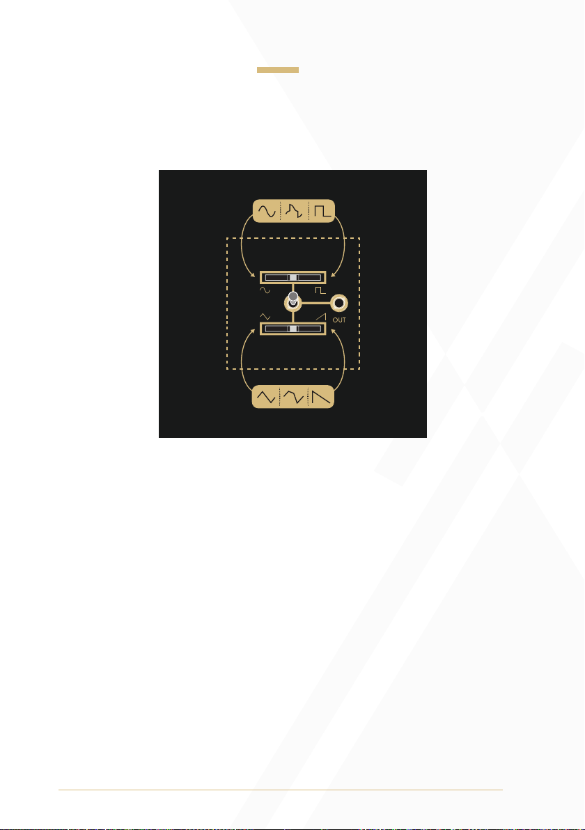
Waveform Crossfade
The Waveform Crossfade section of each oscillator includes a
Waveform Output, two Waveform Crossfaders, and a Waveform
Selection Toggle.
Oscillator 1: If the Waveform Selection Toggle is in the up position, the
signal present at the Waveform Output will smoothly morph between a
sine waveform and a triangle waveform as the Waveform Crossfader
moves from left to right. If the Waveform Selection Toggle is in the
down position, the signal present at the Waveform Output will smoothly
morph between a ramp waveform and a square waveform as the
Waveform Crossfader moves from left to right.
Oscillator 2: If the Waveform Selection Toggle is in the up position, the
signal present at the Waveform Output will smoothly morph between
a sine waveform and a square waveform as the Waveform Crossfader
moves from left to right. If the Waveform Selection Toggle is in the
down position, the signal present at the Waveform Output will smoothly
morph between a triangle waveform and a ramp waveform as the
Waveform Crossfader moves from left to right.

9
Oscillator 3: If the Waveform Selection Toggle is in the up position, the
signal present at the Waveform Output will smoothly morph between
a sine waveform and a ramp waveform as the Waveform Crossfader
moves from left to right. If the Waveform Selection Toggle is in the down
position, the signal present at the Waveform Output will be a pulse
waveform with a dedicated PWM control.
The PWM knob controls the duty cycle ratio of the pulse waveform.
• Turning the knob clockwise will increase the +/– ratio of the
pulse wave.
• Turning the knob anticlockwise will decrease the +/– ratio of the
pulse wave.
• The range of the PWM knob was chosen to always result in a signal
with an audible duty cycle when used without external
control voltage.
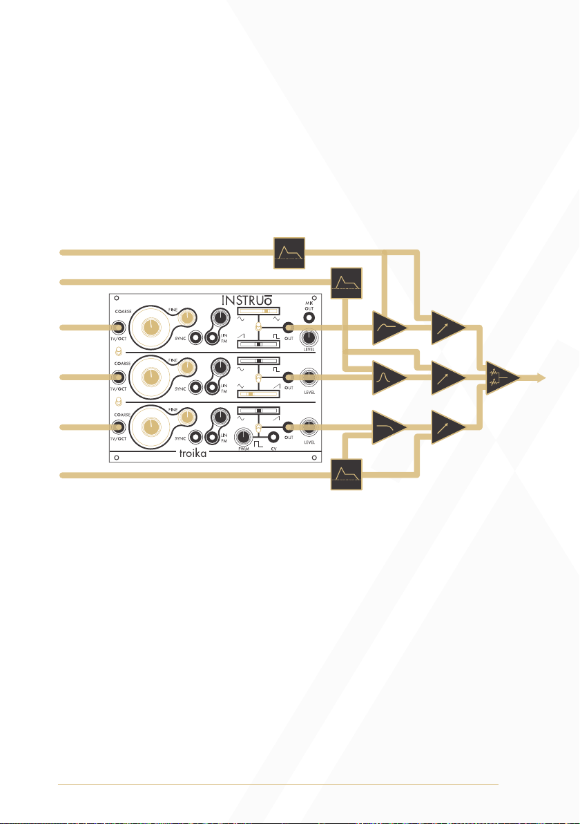
Mixer
The selected waveforms of each oscillator can be mixed with a
dedicated Level control and output at the Mix Output. It is important to
note that the selected waveforms of each oscillator will output from the
Mix Output at unity gain, so clipping can occur with extreme
Level settings.
10
Patch Examples
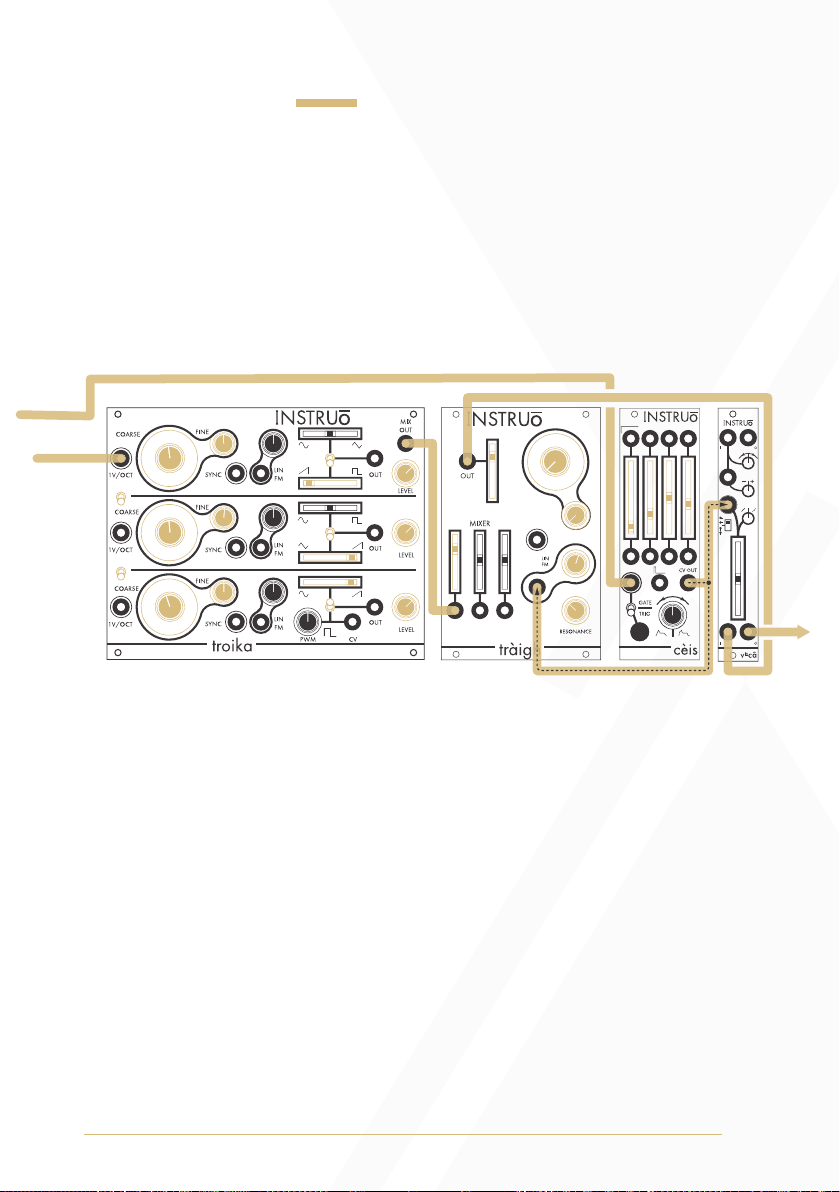
Detuned East Coast Synth Voice:
Summary: The sequencer or keyboard sends voltages to troika while
simultaneously triggering the envelope generator. The CV output of the
envelope generator opens the filter and VCA, allowing troika’s mixed
oscillator signal to pass through. More traditional East Coast patches
would incorporate separate envelope generators for the filter and VCA
Audio Path:
• Set all oscillators to ramp waveforms
• Connect the Mix Output to the audio input of a filter.
• Connect the audio output of the filter to the audio input of a VCA.
• Monitor the audio output of the VCA.
• Set the fundamental frequency of oscillator 1 to a desired position.
• Set the fundamental frequency of oscillator 2 and oscillator 3 to
similar positions, but keep them slightly detuned for a
chorusing effect.
• Set the Level knobs to desired positions.
• Set the cutoff frequency of the filter to a desired position.
• Set the resonance of the filter to a desired position.
• Set the level of the VCA to a desired position.
Output
1V/Oct Signal
Gate Signal

11
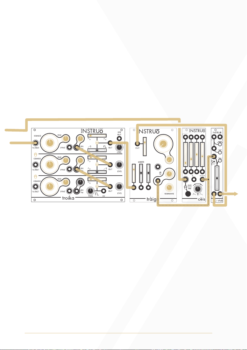
Control Path:
• Connect the 1V/Oct output of a sequencer or keyboard to the 1V/
Oct Input of Oscillator 1.
• Set all 1V/Oct Link Toggles to the down position.
• Connect the gate output of the sequencer or keyboard to the trigger
input of an envelope generator.
• Connect the CV output of the envelope generator to a multiple.
• Connect one copy of the envelope generator CV signal to the CV
input of the filter and set the corresponding CV attenuator to a
desired position.
• Connect a second copy of the envelope generator CV signal to the
CV input of the VCA and set the corresponding CV attenuator to a
desired position.
• Set the envelope stages to desired positions.
12
Triple FM Synth Voice:
Summary: troika’s oscillator 2, called the Modulator in an FM patch,
is modulating the frequency of troika’s oscillator 1, called the Carrier
in an FM patch. troika’s oscillator 3, which is a secondary Modulator
in an FM patch, is modulating the frequency of troika’s oscillator 2. The
sequencer or keyboard sends voltages to troika while simultaneously
triggering the envelope generator. The CV output of the envelope
generator opens the filter and VCA, allowing troika’s signal to pass
through. More traditional East Coast patches would incorporate
separate envelope generators for the filter and VCA.
Audio Path:
• Create an East Coast Synth Voice audio path using the sine
waveform of troika’s oscillator 1.
Control Path:
• Create an East Coast Synth Voice control path.
• Connect the sine waveform of troika’s oscillator 2 to the Linear FM
Input of oscillator 1.
• Connect the sine waveform of troika’s oscillator 3 to the Linear FM
Input of oscillator 2.
• Set the Linear FM Attenuators of troika’s oscillator 1 and oscillator
2 to desired positions.
Output
1V/Oct Signal
Gate Signal
13
Polyphonic East Coast Synth Voice:
Summary: Three sequencers or keyboards send voltages to troika’s
three separate oscillators while simultaneously triggering envelope
generators. The CV output of the envelope generators open the filters
and VCAs, allowing troika’s signals to pass through. More traditional
East Coast patches would incorporate separate envelope generators for
the filters and VCAs.
Audio Path:
• Set all oscillators to desired waveforms
• Connect each Waveform Output to the audio inputs of
separate filters.
• Connect the audio output of the filters to the audio inputs of separate
VCAs.
• Connect the audio outputs of the VCAs to a mixer.
• Monitor the audio output of the mixer.
• Set the fundamental frequency of all oscillators to unison.
• Set the cutoff frequency of the filters to desired positions.
• Set the resonance of the filters to desired positions.
• Set the level of the VCAs to desired positions.
Output
1V/Oct Signal 1
1V/Oct Signal 2
1V/Oct Signal 3
Gate Signal
Gate Signal
Gate Signal

14
Control Path:
• Connect the 1V/Oct output of three separate sequencers or key-
boards to the individual 1V/Oct Inputs of troika.
• Connect the gate outputs of the sequencers or keyboards to the
trigger inputs of three separate envelope generators.
• Connect the CV outputs of the envelope generators to three
separate multiples.
• Connect one copy of the envelope generator CV signals to the CV
inputs of the filters and set the corresponding CV attenuators to
desired positions.
• Connect a second copy of the envelope generator CV signals to the
CV inputs of the VCAs and set the corresponding CV attenuators to
desired positions.
• Set the envelope stages of each envelope to desired positions.
This device meets the requirements of the following standards: EN55032,
EN55103-2, EN61000-3-2, EN61000-3-3, EN62311.
Manual Author: Collin Russell
Manual Design: Dominic D’Sylva
Table of contents
Other Instruo Power Tools manuals


