Instruo I-o47 User manual

I-ō47
Multimode Resonator / Filter
User Manual


3
Description
I-ō47 Multimode Resonator/Filter is a modern take on a vintage
circuit design inspired by the classic synthesisers from the early 1970s.
Unlike many multimode filters, I-ō47 has a steep -18dB/oct slope with
interpolating inputs and tameable resonance.
Although inspired by the past, this module was designed with new
ideas, new features, and most importantly - new quirks. A hybrid design
of matched transistor pairs and precision op-amps was used to create
the circuit’s semi-discrete VCAs, making the I-ō47 a beast of its
own variety.
With on-board limiter/waveshaper, exponential frequency modulation,
pingable resonance, inverted input, and crossfading and mixing
capabilities, I-ō47 fits in every patch.
Features
• Simultaneous low pass, high pass, band pass, and notch filter types
• Self-oscillating resonance with feedback toggle
• 1V/Oct tracking
• Strike input for pingable resonance
• Notch offset with CV control
• Limiter/waveshaper
• Inverting input

4
Installation
1. Confirm that the Eurorack synthesizer system is powered off.
2. Locate 4 HP of space in your Eurorack synthesizer case.
3. Connect the 10 pin side of the IDC power cable to the 2x5 pin
header on the back of the module, confirming that the red stripe on
the power cable is connected to -12V.
4. Connect the 16 pin side of the IDC power cable to the 2x8 pin
header on your Eurorack power supply, confirming that the red
stripe on the power cable is connected to -12V.
5. Mount the Instruō I-ō47 in your Eurorack synthesizer case.
6. Power your Eurorack synthesizer system on.
Note:
This module has reverse polarity protection.
Inverted installation of the power cable will not damage the module.
Specifications
• Width: 14 HP
• Depth: 27mm
• +12V: 50mA
• -12V: 50mA

5
GAIN
IN
Q
COARSE
FINE
1V/OCT
MULTIMODE RESONATOR/FILTER
LIM
FM
LP
BP
HP
CV
N
fc
+–
47
–
fc
1
1/2
1/4
2
4
I-ō47 |öK-əU-'fɔ:ti-'sEv(ə)n | noun (signal processing) the in’s and
out’s of a classic multimode filter/resonator
Key
1. Input
2. Limiter Toggle
3. Gain
4. Inverting Input
5. Low Pass Output
6. Band Pass Output
7. High Pass Output
8. Notch Output
9. Course
10. Fine
11 . FM Input
12. FM Attenuverter
13. 1V/Oct Input
14. Notch
15. Notch CV Input
16. Q
17. Q CV Input
18. Feedback Toggle
19. Strike Input
5
1
4
6
7
8
9
10
11
12
13
14
15
16
17
2
3
1819

6
Input & Output
Input: Audio input of the filter.
• The signal present at the Input will output from all filter types
simultaneously.
Limiter Toggle: The Limiter Toggle sets a fixed level tanh[3] circuit.
Limiting is only applied to the signal present at the Input.
• When the toggle is in the up position, limiting/waveshaping
is bypassed.
• When the toggle is in the down position, limiting/waveshaping
is enabled.
Gain: The Gain fader affects the signal present at the Input.
• If the fader is in the up position, the signal present at the Input will be
at its full scale amplitude.
• If the fader is in the down position, the signal present at the Input will
be fully attenuated.
• If limiting is enabled, the centre position of the Gain fader is
optimised as a “sweet spot” for versatile general purpose use.
Inverting Input: Inverting audio input of the filter.
• The signal present at the Inverting Input is inverted and will output
from all filter types simultaneously.
• The level of the signal present at the Inverting Input is inversely
proportional to the level of the Qparameter. As resonance
increases, the signal present at the Inverting Input decreases.
• This functionality can be used for dynamic signal blending.
Low Pass Output: Low pass filter output.
• Any harmonics above the cutoff frequency are attenuated.

7
Band Pass Output: Band pass filter output.
• Any harmonics above or below the centre frequency are attenuated.
High Pass Output: High pass filter output.
• Any harmonics below the cutoff frequency are attenuated.
Notch Output: Notch filter output.
• This is also known as a Band Stop Filter or a Band Rejection Filter.
• Any harmonics within the stop band are attenuated.

8
Frequency Modulation
Coarse: The Coarse knob controls the cutoff frequency of the low pass
and high pass filters and the centre frequency of the band pass and
notch filters.
• The cutoff frequency is the point at which the filtered signal is
reduced by 3dB in amplitude.
• The centre frequency is the midpoint between the cutoff frequencies
set by the low pass and high pass filters.
• Turning the knob clockwise will increase the cutoff/
centre frequency.
• Turning the knob anticlockwise will decrease the cutoff/
centre frequency.
• If I-ō47 is used as an oscillator, the knob controls the fundamental
frequency of the oscillator.
• Range: ~16Hz - 16KHz.
Fine: The Fine knob is used for minute control of the cutoff frequency
of the low pass and high pass filters and the centre frequency of the
band pass and notch filters. Fine tuning is relative to the value set by the
Coarse knob.
• Turning the knob clockwise will increase the cutoff frequency.
• Turning the knob anticlockwise will decrease the cutoff frequency.
• If I-ō47 is used as an oscillator, the knob controls the fundamental
frequency of the oscillator.
FM Input: The FM Input is a bipolar control voltage input for the cutoff/
centre frequency and applies exponential frequency modulation.
• Control voltage is scaled by the FM Attenuverter and sums with the
level set by the Coarse and Fine knobs.
• If I-ō47 is self-oscillating, the FM Input can be used for exponential
frequency modulation of the generated sine waveform.

9
FM Attenuverter: The FM Attenuverter determines the depth of
frequency modulation applied to the cutoff/centre frequency.
• Turning the knob clockwise will increase the depth of exponential
frequency modulation.
• Turning the knob anticlockwise will increase the depth of
exponential frequency modulation with inverted polarity.
• Centring the knob will attenuate the control voltage signal.
1V/Oct Input: The 1V/Oct Input is a bipolar control voltage input for
the cutoff/centre frequency.
• This is a dedicated exponential frequency control input which
can be used for precise frequency modulation such as ‘keyboard
tracking’.
• If I-ō47 is self-oscillating, the 1V/Oct Input can be used for
consistent pitch tracking of the sine waveform, effectively making
I-ō47 a quadrature sine waveform oscillator.
• Control voltage is summed with the level set by the Coarse and
Fine knobs.
Notch: The Notch knob controls the centre frequency offset of the notch
response output. This parameter affects the Notch Output only.
The numbers surrounding the Notch knob depict a multiplier indicating
an approximate octave offset from the centre frequency.
• ¼ = 0.25 x centre frequency (-2 octave offset). [towards high
pass response]
• ½ = 0.5 x centre frequency (-1 octave offset). [towards high
pass response]
• 1 = centre frequency (0 octave offset). When the knob is set to 1, the
Notch Output is a traditional symmetrical notch filter.
• 2 = 2 x centre frequency (+1 octaves offset). [towards low
pass response]
• 4 = 4 x centre frequency (+2 octave offset). [towards low
pass response]

10
• At the outer extremities of the Notch knob the Notch Output will
duplicate the Low Pass Output (anti-clockwise) or the High Pass
Output (clockwise).
Notch CV Input: The Notch CV Input is a bipolar control voltage input
for the Notch parameter. Signal present at the Notch CV Input will
affect the Notch Output only.
• Control voltage is summed with the knob position.
• Input range: 0V - 5V

11
Resonance
Q: The Qknob determines the level of feedback from the filter’s output
to its input.
• This is also known as the Resonance, Emphasis, or Feedback.
• With resonance introduced, the cutoff frequency of the low pass and
high pass filters accentuate while the centre frequency of the band
pass and notch filters inversely scales in amplitude.
• Turning the knob clockwise will increase resonance.
• Turning the knob anticlockwise will decrease resonance.
Q CV Input: The Q CV Input is a bipolar control voltage input for Q.
• Control voltage is summed with the knob position.
• Input range: -/+ 8V.
Feedback Toggle: The Feedback Toggle enables and disables internal
routing of the Band Pass Output to I-ō47 input. When enabled,
increasing Qcan result in self-oscillation.
• If the toggle is in the up position, feedback is enabled.
• If the toggle is in the down position, feedback is disabled.
• If the Qknob is at its maximum value and there is no input signal,
I-ō47 will self-oscillate as a stable sine waveform.
Strike Input: Rising edge signals present at the Strike Input excite the
resonance of I-ō47.
• Gate and trigger signals present at the Strike Input will ping
the resonance.
• Audio rate waveforms present at the Strike Input result effects similar
to hard synchronisation.
• It’s important to note that the Strike Input is not a low pass gate input
and will not affect the cutoff frequency. Only the resonance
is affected.
12
Patch Examples
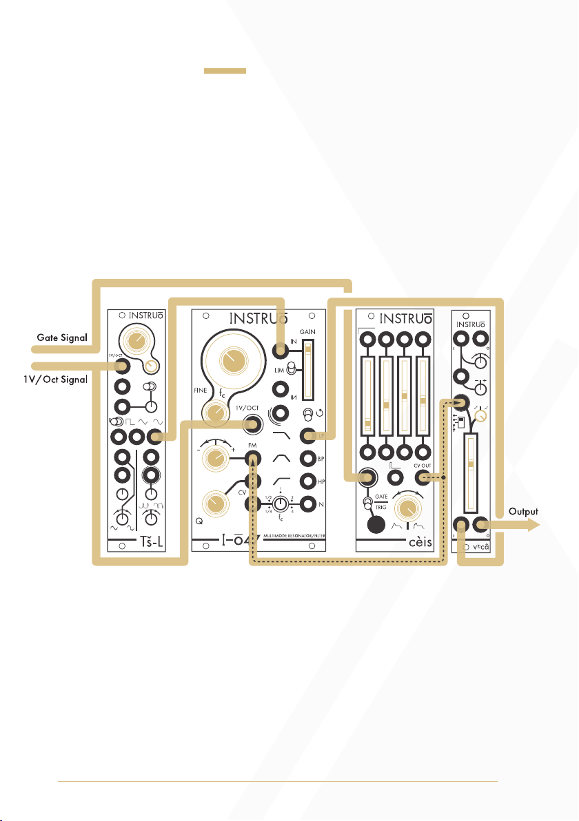
East Coast Synth Voice:
Summary: The sequencer or keyboard sends voltages to the oscillator
while simultaneously triggering the envelope generator. The CV output
of the envelope generator opens I-ō47 and the VCA, allowing the
oscillator signal to pass through. More traditional East Coast patches
would incorporate separate envelope generators for I-ō47 and
the VCA.
Audio Path:
• Connect the desired waveform of an oscillator to the Input of I-ō47.
• Connect the Low Pass Output of I-ō47 to the audio input of a VCA.
• Monitor the audio output of the VCA.
• Set the fundamental frequency of the oscillator to a desired position.
• Set the Gain fader to its maximum setting.
• Set the Coarse and Fine knobs to desired positions.

13
• Set the Qknob to a desired position.
• Set the level of the VCA to a desired position.
Control Path:
• Connect the 1V/Oct output of a sequencer or keyboard to a
buffered multiple.
• A buffered multiple will keep the signal from dropping voltage
when split.
• Connect two copies of the 1V/Oct CV signal to the 1V/Oct input
of the oscillator and the 1V/Oct Input of I-ō47. This is known as
Keyboard Tracking and allows I-ō47 to track the sequencer or
keyboard voltage. As higher voltages are generated, the cutoff
frequency increases.
• Connect the gate output of the sequencer or keyboard to the trigger
input of an envelope generator.
• Connect the CV output of the envelope generator to a multiple.
• Connect one copy of the envelope generator CV signal to the FM
Input of I-ō47 and set the FM Attenuverter to a desired
positive position.
• Connect a second copy of the envelope generator CV signal to the
CV input of the VCA and set the corresponding CV attenuator to a
desired position.
• Set the envelope stages to desired positions.

14
Sine Wave Generator:
Summary: With feedback enabled, peaking the resonance of I-ō47
forces it to self-oscillate as a pure sine waveform. Once the waveform
is generated, it can then be patched through a VCA as a simple synth
voice patch. This was often the technique to create sine waveforms in the
early days of electronic synthesiser music. In the simplest of contexts, a
second filter in the audio path is not needed, because a sine waveform
only loses amplitude when patched through a filter. This is because there
are no other harmonics to attenuate, only the fundamental.
Audio Path:
• Connect the Low Pass Output of I-ō47 to the audio input of a VCA.
• Enable feedback by setting the Feedback Toggle to its up position.
• Set the Qknob fully clockwise. Without an input signal, I-ō47
resonantes as a pure sine waveform.
• Set the Coarse and Fine knobs to desired positions. In this patch, the
Coarse and Fine knobs are frequency (pitch) controls.
• Set the level of the VCA to a desired position.
Output
Gate Signal
1V/Oct Signal

15
Control Path:
• Connect the 1V/Oct output of a sequencer or keyboard to the
1V/Oct Input of I-ō47.
• Connect the gate output of the sequencer or keyboard to the trigger
input of an envelope generator.
• Connect the envelope generator CV output to the CV input of the
VCA and set the corresponding CV attenuator to a desired position.
• Set the envelope stages to desired positions.
16
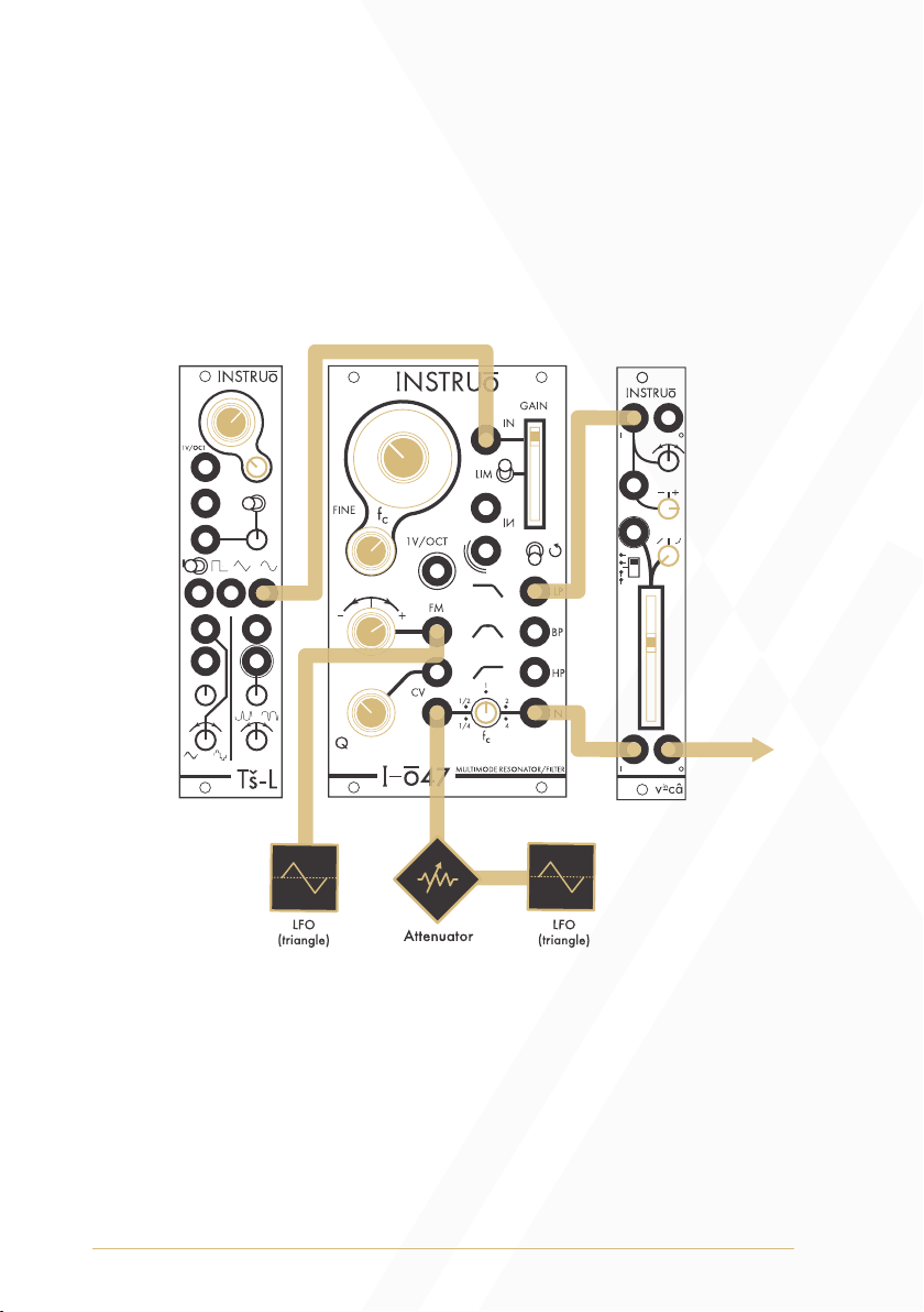
Set Phaser To Stun:
Summary: One bipolar LFO modulates the cutoff frequency of the low
pass filter while a second bipolar LFO modulates the centre frequency
of the notch filter. A gate or trigger signal can be used to reset the cycle
of the LFOs. LFOs can be free running, or in synchronized patterns, such
as fixed quadrature, phase shifted, or multiplied/divided.
Audio Path:
• Connect the desired waveform of an oscillator to the Input of I-ō47.
• Connect the Low Pass Output of I-ō47 to an audio input of a mixer.
• Connect the Notch Output of I-ō47 to a second audio input of
a mixer.
• Monitor the audio output of the mixer.
Output

17
• Set the fundamental frequency of the oscillator to a desired position.
• Set the Gain fader to its maximum setting.
• Set the Coarse and Fine knobs to desired positions.
• Set the Qknob to a desired position.
• Set the Notch knob to 1, its centre position.
• Set the level of both channels of the mixer to be equal.
Control Path:
• Connect a bipolar LFO to the FM Input and set the FM Attenuverter
to a desired position.
• Connect a second attenuated bipolar LFO to the Notch CV Input.
18
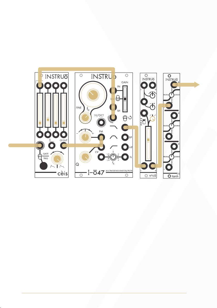
Kick Drum:
Summary: A gate or trigger signal triggers cèis.The attack gate output of
cèis pings the resonance of I-ō47 via the Strike Input. The CV output of
cèis modulates the cutoff frequency of I-ō47.
Audio Path:
• Monitor the Low Pass Output or Band Pass Output.
• Set the fundamental frequency of the kick drum sound using the
Coarse and Fine knobs.
• Disable feedback by setting the Feedback Toggle to its
down position.
• Set the Qknob to a desired position. This sets the decay time of the
amplitude for the kick drum sound.
• For a more aggressive kick drum sound, connect the Low Pass
Output or the Band Pass Output of I-ō47 to the input of tanh[3].
Monitor the output of tanh[3].
Gate Signal
Output

19
Control Path:
• Connect a gate or trigger signal source to the gate/trig input
of cèis.
• Connect the attack gate output of cèis to the Strike Input.
• Connect the CV output of cèis to the FM Input and set the FM
Attenuverter just to the right of its centre position. This sets the
amount of pitch modulation for the kick drum sound.
• Set the shape knob of cèis to a logarithmic/exponential
response curve.
• Set the attack, sustain, and release faders of cèis to their
minimum positions.
• Set the decay fader of cèis to a short decay. This sets the decay time
of the pitch modulation for the kick drum sound.
20
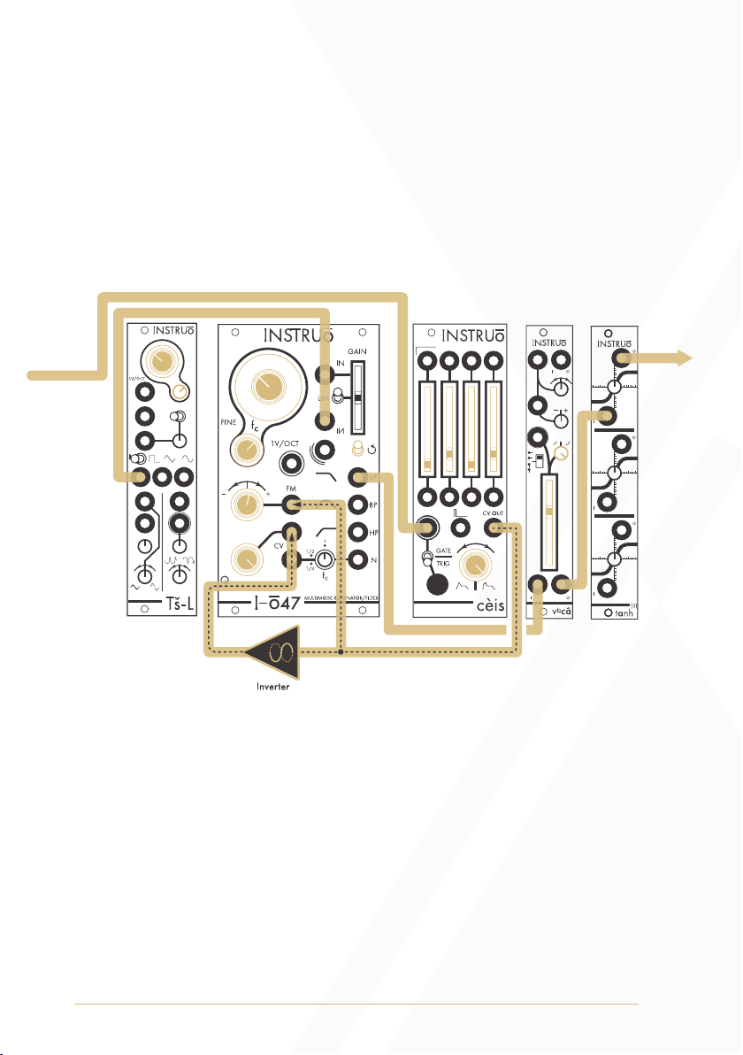
Kick Drum 2:
Summary: A gate or trigger signal source triggers cèis.The attack gate
output of cèis pings the resonance of I-ō47 via the Strike Input. The CV
output of cèis modulates the cutoff frequency of I-ō47. An inverted copy
of the CV output of ceis decreases the amount of resonance of I-ō47,
crossfading between the oscillator and silence.
Audio Path:
• Connect a square waveform of an oscillator to the Inverting Input
of I-ō47.
• Monitor the Low Pass Output.
• Set the fundamental frequency of the oscillator to a desired position.
• Set the fundamental frequency of I-ō47 to match the fundamental
frequency of the oscillator using the Coarse and Fine knobs (some
detuning is encouraged and will result in different tonal resonances).
• Disable feedback by setting the Feedback Toggle to its
down position.
Gate Signal
Output
Other Instruo Synthesizer manuals

Instruo
Instruo athru User manual

Instruo
Instruo ceis User manual

Instruo
Instruo Dual Looper User manual

Instruo
Instruo harmonaig User manual

Instruo
Instruo Ts-L User manual

Instruo
Instruo Cs-L User manual

Instruo
Instruo Cs-L User manual

Instruo
Instruo OCHD LFO User manual

Instruo
Instruo Neoni User manual

Instruo
Instruo Tagh User manual


