Instruo ceis User manual

cèis
ADSR
User Manual


3
Description
The Instruō cèis is a fully analogue voltage controlled ADSR envelope
generator. The ADSR function generator is the model pioneered by
the East Coast mindset and is extensively used in subtractive synthesis
patches. cèis gives the ability to externally control the attack, decay,
sustain, and release stages of the envelope while also emitting trigger
and gate signals for each segment, offering maximum versatility from a
classic tool.
Features
• Voltage control over every stage
• Individual gate outputs for each stage
• Combined trigger output for all stages
• Linear to logarithmic/exponential envelopes
• Manual gate/trigger button
• Two envelope reset modes

4
Installation
1. Confirm that the Eurorack synthesizer system is powered off.
2. Locate 8 HP of space in your Eurorack synthesizer case.
3. Connect the 10 pin side of the IDC power cable to the 2x5 pin
header on the back of the module, confirming that the red stripe on
the power cable is connected to -12V.
4. Connect the 16 pin side of the IDC power cable to the 2x8 pin
header on your Eurorack power supply, confirming that the red
stripe on the power cable is connected to -12V.
5. Mount the Instruō cèis in your Eurorack synthesizer case.
6. Power your Eurorack synthesizer system on.
Note:
This module has reverse polarity protection.
Inverted installation of the power cable will not damage the module.
Specifications
• Width: 8HP
• Depth: 27mm
• +12V: 60mA
• -12V: 30mA

5
cèis
GATE IN
GATE OUTPUTS
COMBINED TRIGGER OUTPUT
GATE IN
LIN ADSR OUT
LOG/EXPO
ADSR OUT
GATE
TRIG
ADSR
ADSR
ADSR
ADSR
cèis | si:s | noun (envelope) a containing structure or layer, a curve
joining the successive peaks of a modulated wave
Key
1. Gate/Trig Button
2. Gate/Trig Toggle
3. Gate/Trig Input
4. CV Output
5. Combined Trigger Output
6. Shape
7. Attack Fader
8. Decay Fader
9. Sustain Fader
10. Release Fader
11 . Attack Gate Output
12. Decay Gate Output
13. Sustain Gate Output
14. Release Gate Ouput
15. Attack CV Input
16. Decay CV Input
17. Sustain CV Input
18. Release CV Input
5
3
1
2
4
6
1615 17 18
7
89
10
11 14
12 13

6
Global Controls
CV Output: The CV Output is the envelope’s control voltage output.
• Output range: 0V - 10V.
Gate/Trig Input: An envelope signal will output from the CV Output
when a gate or trigger signal is present at the Gate/Trig Input.
• Voltage threshold: 3V.
Gate/Trig Button: An envelope signal will output from the CV Output
when the Gate/Trig Button is pressed.
• This button will illuminate representing the contour of the generated
envelope signal.
Gate/Trig Toggle: The Gate/Trig Toggle can be set to two different
modes. Their names suggest the optimum control signal, but gates and
triggers can be used effectively in either mode with differing results.
Gate Mode:
• When set to Gate Mode and gate signals are received at the
Gate/Trig Input, all envelope stages will complete as expected.
Attack and Decay will complete their durations while held. Sustain
defines the voltage level of the envelope for as long as the gate is
held. The Release stage activates on the falling edge of the gate and
decays to 0V at its defined duration.
GA
TE IN
LIN ADSR OUT
LOG/EXPO
ADSR OUT
GATE
TRIG
GATE IN

7
• A trigger signal at the Gate/Trig Input (or a gate signal with a
duration shorter than the Attack and/or Decay stages), will force
the envelope to prematurely jump to the Release stage.
Trig Mode:
• When set to Trig Mode and gate signals are received at the Gate/
Trig Input, all envelope stages will complete as expected if the gate
length exceeds the durations of both Attack and Decay.
• A trigger signal at the Gate/Trig Input will force the envelope to
complete the Attack stage and then immediately enter the
Release stage.
Shape: The Shape parameter controls the envelope’s contours.
• Turning the knob anticlockwise will set the envelope to a linear
response curve.
• Turning the knob clockwise will set the envelope to a logarithmic/
exponential response curve. This setting will have a logarithmic
GATE OUTPUTS
COMBINED TRIGGER OUTPUT
AD
SR
AD
SR
ADSR

8
Attack contour with exponential Decay and Release contours,
similar to classic East Coast ADSR circuits.
• The Shape parameter can smoothly morph between the two
extreme response curves.
Combined Trigger Output: The Combined Trigger Output will generate
trigger signals at the beginning of each envelope stage.
• Output voltage: 10V.
GATE OUTPUTS
COMBINED TRIGGER OUTPUT
ADSR
ADSR
AD
SR

9
Attack
The Attack fader defines the onset duration of the envelope. The value
set by this control is measured in the time domain.
• Moving the fader downward will increase the speed of the
attack time.
• Moving the fader upward will decrease the speed of the attack time.
• Time range: ~3ms - ~10s.
Attack CV Input: The Attack CV Input is a unipolar positive control
voltage input for the Attack parameter.
• Control voltage is summed with the fader position.
• Time range: With negative control voltage, the lowest time reduces
to ~0.4ms.
Attack Gate Output: A gate signal will emit from the Attack Gate
Output and will be high for the duration of the attack stage.
• Output voltage: 10V.
Decay
The Decay fader defines the time it takes to reach the sustain stage once
the attack stage has been completed. The value set by this control is
measured in the time domain.
• Moving the fader downward will increase the speed of the
decay time.
• Moving the fader upward will decrease the speed of the
decay time.
• Time range: ~3ms - ~12s.
Decay CV Input: The Decay CV Input is a unipolar positive control
voltage input for the Decay parameter.
• Control voltage is summed with the fader position.
• Time range: With negative control voltage, the lowest time reduces
to ~0.4ms.
Decay Gate Output: A gate signal will emit from the Decay Gate
Output and will be high for the duration of the decay stage.
• Output voltage: 10V.

10
Sustain
The Sustain fader defines the resting voltage level of the envelope
signal once the decay stage has been completed. The value set by this
control is not measured in the time domain, but instead is measured as
a variable voltage level. Once the attack and decay stages have been
completed, the sustain stage will be active until the gate signal present
at the Gate/Trig Input is low.
• Moving the fader downward will decrease the sustain level.
• Moving the fader upward will increase the sustain level.
AD Envelope: If the fader is in the down
position, the sustain stage will be omitted
and the envelope will act as an AD
envelope (Attack Decay envelope).
ASR Envelope: If the fader is in the up
position, the sustain stage will be as high
as possible and the envelope will act as an
ASR envelope (Attack Sustain Release).
ADSR Envelope: In other words, in order
to access all stages of the ADSR envelope,
the sustain stage cannot be in either of its
extreme settings.
• Output range: 0V - 10V.
Sustain CV Input: The Sustain CV Input is a unipolar positive control
voltage input for the Sustain parameter.
• Control voltage is summed with the fader position.
• Input range: 0V - 10V.
LINEAR AD ENVELOPE
VOLTS
TIME
LINEAR ASR ENVELOPE
VOLTS
TIME
VOLTS
LINEAR ADSR ENVELOPE
TIME

11
Sustain Gate Output: A gate signal will emit from the Sustain Gate
Output and will be high for the duration of the sustain stage.
• Output voltage: 10V.
Release
The Release fader defines the time it takes to reach 0V once the sustain
stage has been completed. The value set by this parameter is measured
in the time domain.
• Moving the fader downward will increase the release time.
• Moving the fader upward will decrease the release time.
• Time range: ~3ms - ~12s.
Release CV Input: The Release CV Input is a unipolar positive control
voltage input for the Release parameter.
• Control voltage is summed with the fader position.
• Time range: With negative control voltage, the lowest time reduces
to ~0.4ms.
Release Gate Output: A gate signal will emit from the Release Gate
Output and will be held high for the duration of the release stage.
• Output voltage: 10V.

12
Patch Examples
East Coast Synth Voice:
Summary: The sequencer or keyboard sends voltages to the oscillator
while simultaneously triggering cèis. The CV Output of cèis opens the
filter and VCA, allowing the oscillator signal to pass through. More
traditional East Coast patches would incorporate separate cèis modules
for the filter and VCA.
Audio Path:
• Connect the desired waveform of an oscillator to the audio input of
a filter.
• Connect the audio output of the filter to the audio input of a VCA.
• Monitor the audio output of the VCA.
• Set the fundamental frequency of the oscillator to a desired position.
• Set the cutoff frequency of the filter to a desired position.
• Set the resonance of the filter to a desired position.
• Set the level of the VCA to a desired position.
Output
1V/Oct Signal
Gate Signal

13
Control Path:
• Connect the 1V/Oct output of a sequencer or keyboard to the 1V/
Oct input of the oscillator.
• Connect the gate output of the sequencer or keyboard to the Gate/
Trig input of cèis.
• Connect CV Output of cèis to a multiple.
• Connect one copy of the cèis CV signal to the cutoff frequency
CV input of the filter and set the corresponding CV attenuator to a
desired position.
• Connect a second copy of the cèis CV signal to the CV input of the
VCA and set the corresponding CV attenuator to a desired position.
• Set the Shape knob its maximum setting for a logarithmic/
exponential response curve.
• Set the Attack,Decay,Sustain,and Release settings to a
desired position.
14
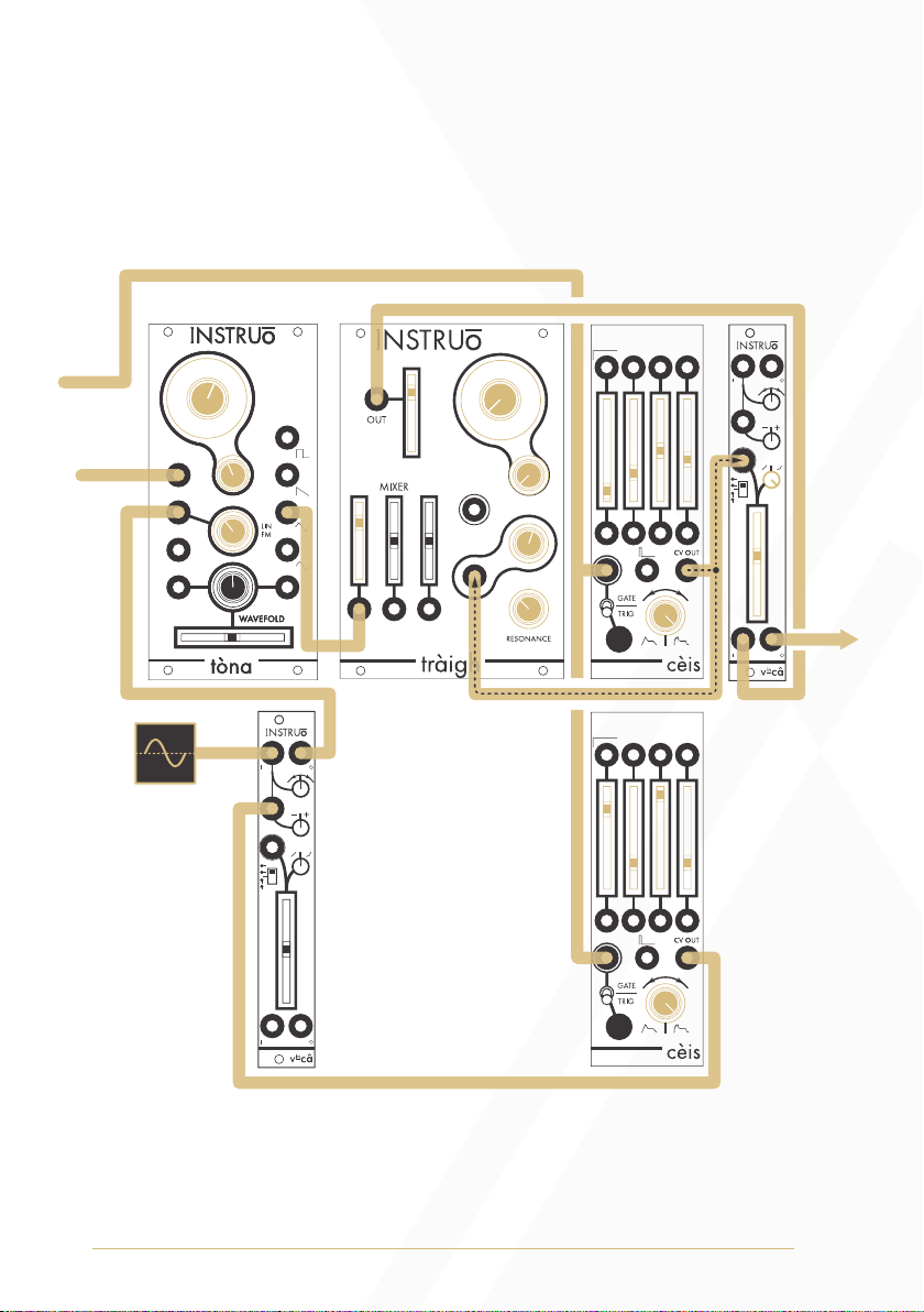
Vibrato Swell:
Summary: Every time the sequencer or keyboard changes state, the
CV signal of cèis 2 slowly opens VCA 2, increasing the amount of
modulation the LFO can apply to the FM input of the oscillator.
Audio Path:
• Create the East Coast Synth Voice audio path.
Output
1V/Oct Signal
Gate Signal
LFO
(sine)

15
Control Path:
• Create the East Coast Synth Voice control path.
• Connect the CV output of an unsynchronised LFO to the input of a
VCA and set the rate of the LFO to a desired position.
• Connect the output of the VCA 2 to the FM input of the oscillator.
• Increase the CV attenuator of the FM input if needed.
• Instead of connecting the gate output of the sequencer or keyboard
to the Gate/Trig Input of just one cèis, connect it to a multiple.
• Connect one copy of the sequencer or keyboard gate signal to the
CV input of the cèis 1.
• The CV Output of cèis 1 should still be connected to a multiple and
modulating both the cutoff frequency of the filter and the amplitude
of the VCA.
• Connect a second copy of the sequencer or keyboard gate signal to
the Gate/Trig Input of the cèis 2.
• Connect the CV Output of cèis 2 to the CV input of VCA 2 and set
the corresponding CV attenuator to a desired position..
• Set a long Attack, short Decay, maximum Sustain, and
short Release.

16
Burst Generator:
Summary: Everytime cèis is triggered, a burst of trigger signals will stike
athrú’s strike input allowing the oscillator’s signal to pass through.
Audio Path:
• Connect the desired waveform of an oscillator to the audio input
of athrú.
• Monitor the audio output of athrú.
• Set the fundamental frequency of the oscillator to a desired position.
• Monitor the output of athrú.
Control Path:
• Connect the Combined Trigger Output to a the strike input
of athrú.
• Set the separate envelope stages at different positions to create the
desired trigger burst.
• Trigger cèis via the Gate/Trig Input or the Gate/Trig Button.
Output

17
This device meets the requirements of the following standards: EN55032,
EN55103-2, EN61000-3-2, EN61000-3-3, EN62311.
Manual Author: Collin Russell
Manual Design: Dominic D’Sylva
Table of contents
Other Instruo Synthesizer manuals

Instruo
Instruo Cs-L User manual

Instruo
Instruo harmonaig User manual

Instruo
Instruo Neoni User manual

Instruo
Instruo athru User manual

Instruo
Instruo Tagh User manual

Instruo
Instruo OCHD LFO User manual

Instruo
Instruo Ts-L User manual

Instruo
Instruo Dual Looper User manual

Instruo
Instruo I-o47 User manual

Instruo
Instruo Cs-L User manual


