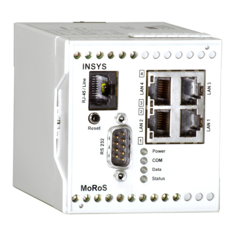
INSYS MoRoS User manual

Manual
MoRoS
Feb-07


Copyright © February 07 INSYS MICROELECTRONICS Gmb
Any duplication of this manual is prohibited. All rights on this documentation and the
devices are with INSYS MICROELECTRONICS Gmb Regensburg.
Restrictions of guarantee
This handbook contains a concise description. The compilation of the text has been made
with the utmost care. Despite all efforts, there may be deviations compared with the ac-
tual functions. No guarantee can therefore be given for the accuracy of the contents. We
can neither take over a legal responsibility nor any liability for incorrect information and
their consequences. Suggestions for improvements and comments are gladly accepted.
Trademarks
The use of a trademark not shown below is not an indication that it is freely available for
use.
MNP is a registered trademark of Microcom Inc.
IBM PC, AT, XT are registered trademarks of International Business Machine Corporation.
INSYS ® is a registered trademark of INSYS MICROELECTRONICS Gmb .
Windows™ is a registered trademark of Microsoft Corporation.
Publisher:
INSYS MICROELECTRONICS Gmb
Waffnergasse 8
D-93047 Regensburg, Germany
Phone: +49 (0)941/56 00 61
Fax: +49 (0)941/56 34 71
e-mail: [email protected]
Internet: http://www.insys-tec.de
Subject to technical changes as well as correction.
Date: Feb-07
Item: 31-22-03.056
Version: 1.1
Language: EN

Contents
4
Feb-07
1 INTRODUCTION.................................................................................................. 6
2 SAFETY INSTRUCTIONS ......................................................................................8
3 SCOPE OF DELIVERY ...........................................................................................9
4 FUNCTION OVERVIEW......................................................................................1
5 DEVICE DESCRIPTION .......................................................................................12
5.1
F
RONT
P
ANEL
.................................................................................................................................. 12
5.2
T
OP
............................................................................................................................................... 13
5.3
B
OTTOM
......................................................................................................................................... 14
6 INSTALLATION..................................................................................................15
7 CONFIGURATION .............................................................................................16
7.1
PC
S
ETUP
....................................................................................................................................... 16
7.1.1
Windows XP.....................................................................................................................................................17
7.1.2
Windows 2000 ................................................................................................................................................ 19
7.1.3
Linux................................................................................................................................................................... 20
7.2
I
NITIAL
C
ONFIGURATION
.................................................................................................................... 21
8 FUNCTIONS ......................................................................................................23
8.1
B
ASIC SETTINGS
............................................................................................................................... 23
8.1.1
User name and password for configuration ...........................................................................................23
8.1.2
MoRoS IP address............................................................................................................................................23
8.1.3
Domain Name Service (DNS).......................................................................................................................24
8.1.4
DynDNS (Dynamic DNS Update) ................................................................................................................25
8.2
DHCP............................................................................................................................................ 26
8.1
ISDN............................................................................................................................................. 28
8.1.1
MSN and authorized caller MSN ................................................................................................................ 28
8.1.2
Send AT commands to ISDN-TA.................................................................................................................. 29
8.2
M
ODEM
......................................................................................................................................... 29
8.2.1
Country code/Wait for dial tone ................................................................................................................ 29
8.2.2
Send AT commands to the modem ...........................................................................................................30
8.3
D
IAL
-
IN
.......................................................................................................................................... 3
8.3.1
Idle time ............................................................................................................................................................30
8.3.2
User for dial-in................................................................................................................................................. 31
8.3.3
IP address for PPP connection ..................................................................................................................... 31
8.3.4
Set gateway for dial-in connections..........................................................................................................32
8.3.5
Automatic callback.........................................................................................................................................33
8.4
D
IAL
-
OUT
....................................................................................................................................... 34
8.4.1
Phone number and provider data for dial-out........................................................................................34
8.4.2
Permanent connection..................................................................................................................................35
8.4.3
Packet filter for Dial-on-Demand resolution...........................................................................................36
8.5
P
ORT FORWARDING
.......................................................................................................................... 38
8.5.1
Port forwarding rules ....................................................................................................................................38
8.5.2
Edit port forwarding rules............................................................................................................................40
8.6
I
NPUTS
........................................................................................................................................... 4
8.6.1
Dial-out .............................................................................................................................................................41
8.6.2
SMS dispatch ...................................................................................................................................................41
8.7
O
UTPUTS
........................................................................................................................................ 43
8.8
S
YSTEM
.......................................................................................................................................... 44
8.8.1
Time....................................................................................................................................................................44
Contents
Feb-07 5
8.8.2
Reset................................................................................................................................................................... 45
8.8.3
Update...............................................................................................................................................................46
8.8.4
Download the configuration....................................................................................................................... 47
8.8.5
MoRoS port settings for web interface and proxy.................................................................................48
8.8.6
Download system data / system messages ............................................................................................48
9 PROXY..............................................................................................................49
9.1
B
ASIC
C
ONFIGURATION
..................................................................................................................... 49
9.2
R
ELOAD
F
UNCTION
........................................................................................................................... 51
1 FAQ ..................................................................................................................52
11 TECHNICAL DATA .............................................................................................55
11.1
M
ECHANICAL
F
EATURES
.................................................................................................................... 55
11.2
P
OWER
S
UPPLY
................................................................................................................................ 55
11.3
I
NPUTS AND
O
UTPUTS
....................................................................................................................... 55
11.4
I
NTEGRATED
S
WITCH
........................................................................................................................ 56
11.5
I
NTEGRATED
C
OMMUNICATION
M
ODULE
.............................................................................................. 56
11.6
I
NTERFACE
C
OMMUNICATION
M
ODULE
................................................................................................ 57
11.6.1
Phone interface (only for MoRoS Modem)............................................................................................... 57
11.6.2
S0 interface (only for MoRoS ISDN) ........................................................................................................... 58
11.7
D
IRECTIVES
..................................................................................................................................... 58
12 SETTINGS FOR TEXT MESSAGES .......................................................................59
12.1
SMS
TO
M
OBILE
T
ELEPHONE
N
ETWORK OR
F
IXED
N
ETWORK
................................................................... 59
12.2
SMS
AS
F
AX
................................................................................................................................... 6
12.3
SMS
AS
E-M
AIL
............................................................................................................................... 6
13 GLOSSARY........................................................................................................61
14 GNU GPL (GNU PUBLIC LICENCE)......................................................................62

MoRoS Introduction
6
Feb-07
1 Introduction
Validity range of the manual
The manual applies to the device MoRoS.
Purpose
This manual is directed primarily at technical staff, in particular:
Programmers
Implementers
Required basics
General knowledge regarding communication technologies is required.
Safety Instructions
This manual includes notes which must be observed in order to avoid material damage.
The warnings and cautions are described as follows:
Caution - Damage of components!
Not observing this note may result in destruction of the device.
Warning!
Failure to comply may result in malfunction.
Note
Notes contain important information which you should observe in par-
ticular.

MoRoS Introduction
Feb-07 7
Online availability
The manuals are available in German and English at http://www.insys-tec.de.
Additional documentation
Please find a complete overview of all AT commands of the communication modules in
the documents: "AT Command Set for Modem" and "AT Command Set for ISDN".
The complete reference for the standard AT commands is available on request.
Technical support
Call technical support at:
E-mail: [email protected]
0941/560061
Repurchasing of legacy systems
According to the new WEEE guidelines, the repurchasing and recycling of legacy systems
for our clients is regulated as follows:
Please send those legacy systems to the following address, carriage prepaid:
Frankenberg-Metalle
Gärtnersleite 8
D-96450 Coburg

MoRoS Safety Instructions
8
Feb-07
2 Safety Instructions
Warning!
Fire hazard when improperly maintained or if the case is opened
improperly!
All areas that can be opened are maintenance areas. Unauthorized
and improper opening of a maintenance area as well as improper
repairs may endanger the user, e.g. through a burnout of the de-
vice.
Only qualified personnel may maintain and open the device.
Warning!
Fire hazard when using an unsuitable power supply!
Using an unsuitable power supply unit could damage the
MoRoS; in this event, the manufacturer will assume no li-
ability. At worst, the device may burn down.
The device may only be operated with a suitable power supply.
Caution!
Danger of short-circuit!
The MoRoS may not be used in wet environments, damp
rooms or close to water. Take care not to let liquids seep
into the MoRoS as this may lead to short circuits.
The device may only be used in splash proof, dry environments.
Warning!
Device breakdown due to flaws in the supply circuit.
If a power failure occurs, the device will not be operational.
We recommend providing a separate circuit for the MoRoS. If other
devices experience short circuits, the MoRoS will thus not be inop-
erative. We also recommend installing suitable overvoltage protec-
tion.
Funktionsübersicht

MoRoS Scope Of Delivery
Feb-07 9
3 Scope Of Delivery
Before you start with the initial operation, please check if all accessories are in-
cluded in the box.
MoRoS Modem/ISDN
1 phone cord TAE-N at RJ12 (only for INSYS MoRoS Modem)
1 phone cord international (only for MoRos Modem)
1 ISDN phone cord S0 (only for INSYS MoRoS ISDN)
1 manual
1 quick installation guide
Please contact your supplier if the content is not complete. Please also check the
MoRoS for shipping damage. Please also refer to your supplier if anything is dam-
aged.
The scope of delivery does not include a power supply.
Please keep the packaging material for possible future shipping or storage.

MoRoS Function Overview
10
Feb-07
4 Function Overview
The MoRoS is a router with an integrated communication device (analogue mo-
dem or ISDN-TA), and an integrated 4-port switch. It has a very compact design
and a plastic housing according to IP40. The MoRoS has the following characteris-
tics, which are described in detail in the following:
Integrated configuration interface and help function
Easy local or remote configuration
4-port switch with 10/100 MBit/s
Integrated communication module (analogue modem or ISDN-TA)
International country settings (up to 97 countries for the analogue mo-
dem)
Dial-in and dial-out function
Dynamic DNS update
Callback function
Port forwarding
Dialing filter for dial-out
Dial-in authentification for up to 10 users
Authentification via PAP, C AP, MS-C AP, MS-C AP 2
D CP server and client
Firmware update (local and remote)
2 digital inputs and 2 digital outputs
Buffered RTC (real time clock), NTP client
Proxy server
The MoRoS partially uses Open Source software, which was published under the
GNU GPL (GNU General Public Licence), the GNU LGPL (GNU Lesser General Public
License), or the BSD licence.
The according source codes can be obtained from INSYS on request.
Caution - Device breakdown
owever, if the MoRoS firmware is modified, or if any other firm-
ware than the one released by INSYS is installed, the warranty for
the device will expire.

MoRoS Function Overview
Feb-07 11
Examples of Use:
The MoRoS can connect two networks to allow each subscriber of one network to
communicate with any subscriber of the other network. The MoRoS can auto-
matically start to establish a connection from each network.
The MoRoS can also connect a network to the Internet. The connection setup takes
place automatically, via local network queries.

MoRoS Device Description
12
Feb-07
5 Device Description
5.1 Front Panel
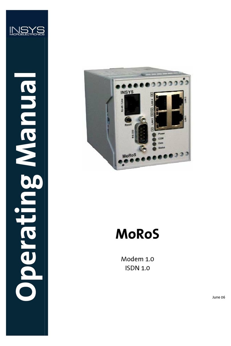
The MoRoS has LEDs to indicate the operating state:
Name
Color
LED off
LED on
Power Green No supply voltage Supply voltage available
Green MoRoS is offline. MoRoS is hooked to the phone line, but there is no usable
data connection yet (O ).
COM
Orange MoRoS has established a usable data connection via the
phone line (CONNECT).
Data Yellow A PPP data packet is transmitted via the phone line.
Status Red MoRoS is ready. MoRoS is not ready (e.g. after being switched on or when
restoring the standard settings).
Green An LAN cable is connected and the port is set to 100 MBit/s.
This LED blinks during data traffic.
1
2
3
4
Yellow
No LAN cable
connected.
An LAN cable is connected and the port is set to 10 MBit/s.
This LED blinks during data traffic.

MoRoS Device Description
Feb-07 13
The reset key has several functions:
Pressing it for a short time (no longer than 1 second) initiates a soft reset. The
MoRoS performs a restart; the integrated communication module is not restarted.
The settings are maintained.
Pressing it for a long time (more than 3 seconds) initiates a hard reset; the inte-
grated communication module is also restarted. Regarding its effect, this equals a
voltage failure. The settings are maintained.
Pressing the reset key three times for a short time. Each keystroke may not last
longer than 1 second. All three keystrokes must be performed within 2 seconds.
The settings are reset to the factory defaults.
As soon as a function of the reset key becomes active, the “Status” LED lights up red.
The RS232 interface has no function.
5.2 Top
Terminal
Meaning
1 OUT 1-NC Output 1 – normally open
2 OUT 1 Output 1
3 OUT 1-NO Output 1 – normally open
4 OUT 2-NC Output 2 – normally open
5 OUT 2 Output 2
6 OUT 2-NO Output 2 – normally open

MoRoS Device Description
14
Feb-07
5.3 Bottom
Terminal
Meaning
17 RS 485 B Reserved
18 RS 485 A Reserved
19 GND Ground
2 Input 2 Input 2
21 Input 1 Input 1
22 GND Ground
23 Reset Reset input
24 GND Ground
25 10..60 VDC Power supply 10V to 60V DC
26 GND Ground
For the voltage supply, please use a power supply which has its own fuse and overvoltage
protection and can supply at least 3W at a DC voltage of 10 V minimum and 60V maxi-
mum.
The reset terminals have the same function as the reset key.
Currently, the terminals for the RS485 interface have no function.

MoRoS Installation
Feb-07 15
6 Installation
1. Mounting on DIN rail
2. Connecting the power supply
a) Connecting the ground connection
b) Connecting the power supply 10…60V DC
Caution - Damage of components!
The minimum value is 1 V DC.
The maximum value is 6 V DC.
3. Switch on power supply
The green ”Power” LED lights up.
4. Connection to the PC
The network card of the PC must be connected to any one of the four MoRoS
Ethernet ports, using the supplied network cable.
5. Connection to the telephone network
The ”RJ45/Line” plug is connected as follows:
- For the MoRoS Modem, via the supplied phone cord with the TAE
(German telephone plug unit).
- For the MoRoS ISDN, via the supplied ISDN cord with the ISDN S0 bus
or with the internal S0 bus of an ISDN phone system.

MoRoS Configuration
16
Feb-07
7 Configuration
The configuration of the MoRoS takes place via a network connection between the Mo-
RoS and a PC.
Configuration requirements:
A PC with network card.
An Internet browser (e.g. Mozilla Firefox, Opera, Konqueror or Internet Explorer).
The operating system of the PC is irrelevant for the configuration. The operating system
must support TCP/IP, it must be possible to use the built-in network card, and a web
browser must be installed.
After the configuration is completed, you can also access the web interface via a dial-up
connection. The function dial-in must be activated for this action. For the remote con-
figuration, the notes in the pertinent chapters regarding the individual configuration
steps must absolutely be observed.
7.1 PC Setup
To enable the communication between the PC and the MoRoS, both devices must be pre-
sent in the same network. Depending on the operating system, the steps for the network
settings will differ.
The MoRoS has a D CP server. It is activated by default. The network configuration
should usually take place automatically.
If this automatic configuration doesn't work, the following chapters will help you to
manually configure the network settings.
Summary PC settings:
1. The IP address must be in the network 192.168.1.X , for example
192.168.1.2; 192.168.1.1 is the IP address of the MoRoS and may
not be used.
2. The network mask must read: 255.255.255.0
3. The gateway address must read: 192.168.1.1
The MoRoS may now be accessed via a browser at the IP address 192.168.1.1.

MoRoS Configuration
Feb-07 17
7.1.1 Windows XP
The Windows XP settings can be accessed via the Explorer (right mouse button on “Start”
-> Explore).
Under “Control Panel” you will find the menu item “Network Connections”. Under this
item, you will find the entry “Local Area Connection”. If this entry is not available yet, you
must first select the network installation assistant to activate the network card.
Right-click on the item “Local Area Connection” to go to “Local Area Connection Proper-
ties”.

MoRoS Configuration
18
Feb-07
Mark the option ”Internet Protocol (TCP/IP)” and click on “Properties” to go to the set-
tings to be configured.
Set the IP address in the new window. We recommend entering 192.168.1.2 as the IP ad-
dress.
We recommend selecting “Obtain DNS server address automatically“ for the DNS setting.
All DNS queries which cannot be handled within the local network will be sent to the
MoRoS. If the function “Dial-out” was activated, MoRoS will automatically establish a
connection, and will handle the DNS query as soon as this connection is activated.
If there is already a DNS server in the local network, its IP address can be entered at this
point.
The MoRoS has the IP address 192.168.1.1. This address must be set as standard gate-
way at the connected terminals.
For the sub network mask, the number 255.255.255.0 must be entered.
The DNS server addresses can be entered optionally. It is required if domain names
should be handled.

MoRoS Configuration
Feb-07 19
7.1.2 Windows 2
The Windows 2000 configuration is similar to the Windows XP configuration.
Right-click the “Start” key and then click on “Explore” to open the Explorer. The network
connections are displayed under “System Control“.
Right-click on “Local Area Connections” and afterwards left-click “Properties” to open the
Local Area Connection
:

MoRoS Configuration
20
Feb-07
Click on “Internet Protocol (TCP/IP)“ to mark the entry. One more click on the button
“Properties” will open the next window:
Set the IP address in the new window. We recommend entering 192.168.1.2 as the IP ad-
dress.
The MoRoS has the IP address 192.168.1.1. This address must be stated as the standard
gateway.
We recommend selecting “Obtain DNS server address automatically“ for the DNS setting.
All DNS queries which cannot be handled within the local network will be sent to the
MoRoS. If “Dial-out” was activated, MoRoS will automatically establish a connection, and
will handle the DNS query as soon as this connection is activated.
If there is already a DNS server in the local network, its IP address can be entered at this
point.
For the sub network mask, the number 255.255.255.0 must be entered.
The DNS server addresses can be entered optionally. It is required if domain names
should be handled.
7.1.3 Linux
We cannot offer a detailed description for the configuration of the IP address in this
manual. Linux distributors supply different tools. The exact steps for the Ethernet inter-
face settings are usually explained in the online help or at so-called “Knowledge Portals“
,or in “Forums“ of the according distributor.
The basic steps for the configuration in a shell:
We assume that the network interface to be configured has the name “eth0”. This is in
most cases the first (and only) network card in the computer. You need "Root rights” for
the configuration.
Other manuals for MoRoS
3
Table of contents
Other INSYS Modem manuals

INSYS
INSYS ADSL 1.1 User manual

INSYS
INSYS MoRoS User manual

INSYS
INSYS Modem 336 LL 2D/4D 5.x Originate / Answer User manual

INSYS
INSYS 336 4.1 User manual

INSYS
INSYS 56k Small INT 2.0 Assembly instructions

INSYS
INSYS 56k Small INT 2.0 User manual

INSYS
INSYS i-modul 336 LL User manual

INSYS
INSYS Pocket ISDN User manual

INSYS
INSYS GSM 4.3 easy User manual

INSYS
INSYS GSM 4.3 I4 User manual