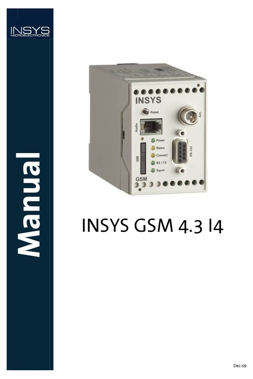
INSYS GSM 4.3 easy User manual

Add-On Manual
INSYS GSM 4.3 easy
Apr-09


Copyright © April 09 INSYS MICROELECTRONICS GmbH
Any duplication of this manual is prohibited. All rights on this documentation and the
devices are with INSYS MICROELECTRONICS GmbH Regensburg.
Trademarks
The use of a trademark not shown below is not an indication that it is freely available for
use.
MNP is a registered trademark of Microcom Inc.
IBM PC, AT, XT are registered trademarks of International Business Machine Corporation.
INSYS ® is a registered trademark of INSYS MICROELECTRONICS GmbH.
Windows™ is a registered trademark of Microsoft Corporation.
Linux is a registered trademark of Linus Torvalds.
Publisher:
INSYS MICROELECTRONICS GmbH
Hermann-Köhl-Str. 22
D-93049Regensburg, Germany
Phone: +49 941 58692-0
Fax: +49 941 58692-45
e-mail: info@insys-icom.com
Internet: http://www.insys-icom.com
Date: Apr-09
Item: 31-22-03.154
Version: 1.0
Language:

Contents
1Scope of Delivery ................................................................................................ 5
2General................................................................................................................ 6
2.1 Application Possibilities of the INSYS GSM 4.3 easy .........................................................6
2.1.1 Remote Control via Mobile Phone or Data Connection...........................................7
2.1.2 Remote Programming via Data Connection...............................................................7
2.2 Possibilities with the Preceding Version INSYS GSM.........................................................7
2.3 Restrictions / Notes ............................................................................................................8
3Installation and Initial Operation....................................................................... 9
3.1 Installation and Initial Operation of the INSYS GSM 4.3 easy...........................................9
3.2 Operation of the INSYS GSM 4.3 easy with the Moeller easy ...........................................9
4Operating Principle........................................................................................... 10
4.1 Configure Alias..................................................................................................................11
4.2 Configure Monitoring.......................................................................................................12
4.3 Configure Time-Scheduled SMS .......................................................................................13
4.4 Manage Configuration Data.............................................................................................13
5Functional Description...................................................................................... 14
5.1 Definitions.........................................................................................................................14
5.1.1 Objects, Instances, Object Short Names................................................................... 14
5.1.2 Alias..................................................................................................................................... 14
5.2 Automatic Actions ............................................................................................................14
5.2.1 Object Instances Monitoring........................................................................................ 14
5.2.2 Time-Scheduled SMS...................................................................................................... 16
5.3 Querying and Controlling via SMS ...................................................................................17
5.3.1 SMS Commands............................................................................................................... 17
5.3.2 Monitoring of an Object Instance............................................................................... 17
5.3.3 Setting an Object Instance ........................................................................................... 19
5.3.4 Status Query..................................................................................................................... 20
5.3.5 Status Change.................................................................................................................. 20
5.4 New History Entries ..........................................................................................................21
6Remote Configuration with EASY-SOFT and INSYS Connect ........................... 22
7Declaration of Conformity................................................................................ 24
8Tables and Diagrams......................................................................................... 25
8.1 List of Tables .....................................................................................................................25
8.2 List of Diagrams ................................................................................................................25
4Apr-09
INSYS GSM 4.3 easy Scope of Delivery
1Scope of Delivery
The scope of delivery for the INSYS GSM 4.3 easy includes all accessories listed below.
Please check if all accessories are included in the box. If a part is missing or damaged,
please contact your distributor.
INSYS GSM 4.3 easy
Cable:
1 serial cable with 9-pin Sub-D connector for the connection to the PC
1 manual INSYS GSM
Additional manual INSYS GSM 4.3 easy
CD-ROM
Optional Accessories
Adapter cable D-SUB 9 pin, male to 9 pin, male
GSM antenna
Outside mounted antenna, magnetic base antenna or patch antenna
Connection cable GSM easy 500 for connecting the INSYS GSM 4.3 easy to a
Moeller easy 500/700 (prod. no.: 31-02-02-011)
Connection cable GSM easy 800 for connecting the INSYS GSM 4.3 easy to a
Moeller easy 800/MFD (prod. no.: 31-02-02-012)
5

General INSYS GSM 4.3 easy
2General
Basically, the INSYS GSM 4.3 easy offers the same technical characteristics and function-
alities as the standard version.
This manual is only an add-on manual and can only be used in connection with the user
manual of the INSYS GSM. The indication of technical data and functional descriptions of
the standard version will be omitted in this manual (if possible). Please refer to the user
manual INSYS GSM.
If the INSYS GSM 4.3 easy behaves differently than the standard version, we will mention
this fact in the according passages.
The INSYS GSM 4.3 easy is available in two versions. These are
INSYS GSM 4.3 easy
INSYS GSM 4.3 easy compact
The INSYS GSM 4.3 easy compact differs by a compact housing for in-wall connection
boxes and the missing audio interface from the INSYS GSM 4.3 easy. Both versions are
referred to as INSYS GSM 4.3 easy in the further course of this manual. If the INSYS GSM
4.3 easy compact differs from the INSYS GSM 4.3 easy, this will be mentioned in particu-
lar in the respective sections.
Supported Moeller easy versions
The following easy models are supported:
easy 500
easy 700
easy 800
easy MFD
The communication protocols of the easy 500 and the easy 700 as well as the protocols
of the easy 800 and easy MFD are identical as file. In the following, we only need to dis-
tinguish between easy 500/700 and easy 800/MFD.
Dedicated connection cables are available for the connection (refer to Optional Accesso-
ries in the in the Scope of Delivery section)
2.1 Application Possibilities of the INSYS GSM 4.3 easy
The object instances (peripherals and extension modules) of the easy device can be
monitored regarding defined conditions or levels, to enable the sending of fault mes-
sages when changes occur. Depending on the used easy model, not all object instances
are available.
6

INSYS GSM 4.3 easy General
The following object instances can be monitored:
Digital inputs
Digital outputs
Digital registers
Analogue inputs
Analogue outputs
Analogue registers (byte registers, word registers, double word registers)
Current program cycle time
LED state for Moeller easy MFD
The fault message consists of one text, which is permanently allocated to the value to be
monitored. Up to 10 object instances can be monitored altogether.
The fault message can be sent in the following format:
Via SMS to a mobile phone
Via SMS to a fixed network telephone (depending on the provider)
Via SMS to a FAX device (depending on the provider)
Via SMS to an E-mail recipient (depending on the provider)
2.1.1 Remote Control via Mobile Phone or Data Connection
Independent from automatic monitoring, various information regarding the current
condition of the easy device can be read or set via SMS or a GSM data connection:
easy status (RUN/STOP/ERROR). The easy status can also be changed from RUN
to STOP or vice versa.
Monitoring of the easy object instances. This message can also be performed
automatically (refer also to the Functional Description section).
Setting of the easy object instances. This can be done from a mobile phone or
via a dial up connection. It will enable you to intervene actively in the process of
the easy control program.
2.1.2 Remote Programming via Data Connection
A dial up connection is established with the help of the dialling program “INSYS Connect”
for the remote programming of the easy device. The supplied program “EASY Soft” by
Moeller is used to program the remote easy device. The INSYS GSM 4.3 easy serves as
remote terminal of the dial up connection and forwards the data transparently to the
Moeller easy device.
2.2 Possibilities with the Preceding Version INSYS GSM
The possibility to control the alarm inputs of the INSYS GSM with pulses, thus triggering
up to 20 fault messages, has been implemented into the device series INSYS GSM and
can still be used. This possibility is not tied to a device and can therefore be used for all
kinds of control types.
7

General INSYS GSM 4.3 easy
Generating pulses or their processing, however, results in the following:
The controller requires additional memory for the functions to generate pulses.
Compact controllers in particular have a rather limited memory for control pro-
grams.
Due to additional functions which have no effect on the actual system function,
the control program will be more complex and confusing.
Programming pulse creation requires effort and time.
Valuable outputs of the compact controllers are used, because they are needed
for the pulse output.
2.3 Restrictions / Notes
Since the INSYS GSM 4.3 easy is connected to the Moeller easy device via a serial
interface, a memory can not be used simultaneously with the INSYS GSM 4.3
easy.
The password protection of the easy device may not be activated. If it is acti-
vated, no communication between INSYS GSM 4.3 easy and the compact con-
troller is possible. However, the INSYS GSM 4.3 easy has its own password pro-
tection, which prevents unauthorized persons without knowledge of the exact
password from remotely accessing the compact controller.
The LCD display needs to be in its original state before the Moeller easy control-
lers can communicate via their RS232 interface. This means, for example, that if
the controller is put into another condition by hitting keys on the device, or if
the control program is manually modified, the user has to leave all sub menus
of the easy device. This is necessary that the INSYS GSM 4.3 easy can communi-
cate with the easy device.
As it is possible to intervene in registers of the current easy control program
with the help of SMS commands via the INSYS GSM 4.3 easy we again refer to
the documentation of the used Moeller easy 800 or easy MFD devices. In the
easy device, the storage location for registers can be used twice; the instances
of the registers should therefore be chosen with care to prevent the registers
from manipulating each other.
Recommendation:
Object Instance from
Bit register M 1
Byte register MB 13
Word register MW 49
Double word register MD 49
Table 1: Recommended assignment of the register instances
8

INSYS GSM 4.3 easy Installation and Initial Operation
3Installation and Initial Operation
This section provides additional information about the connection of the INSYS GSM 4.3
easy to the Moeller easy. You’ll find instructions about the installation and initial opera-
tion of the INSYS GSM 4.3 easy in the enclosed manual of the INSYS GSM.
3.1 Installation and Initial Operation of the INSYS GSM 4.3
easy
Follow the instructions about the installation and initial operation of the INSYS GSM 4.3
easy in the enclosed manual of the INSYS GSM.
3.2 Operation of the INSYS GSM 4.3 easy with the Moeller
easy
For the operation with the Moeller easy, suitable connection cables are available (refer to
Optional Accessories in the Scope of Delivery section of this manual). Alternatively, the
30 cm long INSYS adapter cable may be used.
The connection of the connection cables is described in the respective supplementary
sheet. For connecting the adapter cable, the part of the cable with the fastening nuts is
connected to the easy PC cable of the Moeller device, which is connected to the Moeller
easy device on the other side. The part of the cable with the fastening nuts is connected
to the D-SUB jack of the INSYS GSM 4.3 easy.
Every time the PC and the Moeller easy device are unplugged, the INSYS
GSM 4.3 easy must be restarted (press reset button).
Figure 1: Principal connection of the (INSYS GSM 4.3 easy to the Moeller easy
9

Operating Principle INSYS GSM 4.3 easy
4Operating Principle
This section provides an amendment to the respective section in the enclosed manual of
the INSYS GSM and describes the additional options of the HSComm software for the
INSYS GSM 4.3 easy.
The settings for the Moeller easy™ compact controls are available under the “Moeller
easy(tm)” tab.
Figure 2: Software HSComm - Moeller easy(tm) tab
The series of the used Moeller easy™ compact control is configured in the “Installed
Moeller easy (tm)” section.
Depending on the selected compact controller, the speed of the serial interface is set to
4800 bps or 9600 bps. When the selection is changed, the complete configuration for the
Moeller easy functionality™ is deleted as a precaution. We recommend saving the con-
figuration using “File” -> “Save as” before performing any changes at the controller.
The “Alias” section allows for assigning aliases to object instances.
The “Monitoring” section allows for configuring the monitoring functions of the easy.
The “Time-scheduled SMS” section allows for configuring a time-scheduled SMS for an
alias or an object instance.
The “Configuration data for Moeller easy(tm)” allows for reading, writing, and deleting
the configurations for the Moeller easy™ separately.
10

INSYS GSM 4.3 easy Operating Principle
4.1 Configure Alias
After clicking the button “Configure”, a window is displayed under the field “Alias”,
which is used to allocate aliases to up to 30 object instances. The table is not used to en-
ter data, but to visualize the configuration. The configuration itself takes place below the
table with the help of the pull-down menus or the text field „Name“.
Selecting the alias line is done either with the selection box “No.” or by double-clicking
the according line in the alias table.
Figure 3: Software HSComm - Assign alias window
11

Operating Principle INSYS GSM 4.3 easy
4.2 Configure Monitoring
Clicking the button “Configure” displays the special configuration of the function. The
table is not used to enter data, but to visualize the configuration. The entry takes place
below the table.
Selecting the monitoring line in the configuration window is done either with the selec-
tion box “No.” or by double-clicking the according line in the alias table.
Figure 4: Software HSComm - Configure monitoring window
The displayed settings are only effective when monitoring is turned on in
the main window!
Settings from 1 to 255 seconds are possible for the monitoring interval.
Settings from 1 to 255 minutes are possible for the intervals between sending attempts.
Up to 10 object instances can be monitored altogether. In the text field “Alias” an object
instance which has already been allocated an alias can be selected optionally. If this is
not preferred or if no alias is defined yet, “Manual entry” must be selected. This means
that the monitored object and the preferred instance can be manually selected.
The monitoring type as well as the minimum and maximum value depends on the moni-
tored object instance.
12

INSYS GSM 4.3 easy Operating Principle
4.3 Configure Time-Scheduled SMS
The dedicated configuration of the function appears after pressing the “Configure” but-
ton.
Figure 5: Software HSComm - Time-scheduled SMS window
The displayed settings below are only effective when “Time-scheduled
SMS” is turned on in the main window!
In the text field “Alias” an object instance which has already been allocated an alias can
be selected optionally. If this is not preferred or if no alias is defined yet, “Manual entry”
must be selected. This means that the monitored object and the preferred instance can
be manually selected.
The interval can be selected between 1 and 255 hours.
4.4 Manage Configuration Data
The buttons under “Configuration data for Moeller easy(tm)” will only be displayed after
the INSYS GSM 4.3 easy configuration has been read out once (“Read settings” button).
Figure 6: Software HSComm - manage configuration data
These three buttons will enable you to read, write or delete the INSYS GSM 4.3 easy con-
figuration for the Moeller easy functionality in particular. Reading and writing using
these buttons will be faster than the total transfer via the button Send values, because
the standard functionality does not need to be transferred once more.
13

Functional Description INSYS GSM 4.3 easy
5Functional Description
5.1 Definitions
5.1.1 Objects, Instances, Object Short Names
Programming of the Moeller easy takes place via objects. A digital input, a register, a
counter for operating hours, a comparator, etc. are all examples for objects.
Each object has an object short name. The digital register, for example, has the object
short name "M", the analogue output has the short name "QA".
Several instances of each object are available to the programmer. The easy 500 device,
for example, offers 16 digital registers “M”. The programmer can therefore select the
object instances "M1" to "M16".
5.1.2 Alias
As not only the programmer of the compact controller is responsible for maintenance
and operation of the Moeller easy device, it may not be clear for “outsiders” which object
instance has which function. Therefore, so-called aliases were introduced for the INSYS
GSM 4.3 easy. This offers the possibility to allocate a name that is easy to understand. If
the Moeller easy device controls a waste water system, for example, the digital register
M1 can be allocated the alias "waste water pump1”. If an individual wants to activate the
wastewater pump via mobile phone, using an SMS, he does not need to know that the
register 1 must be used, but simply uses the term “wastewaterpump1”. Up to 30 object
instances all in all can be allocated aliases.
5.2 Automatic Actions
5.2.1 Object Instances Monitoring
The values of the easy object instances are monitored to enable a fault message when
values are changed. Monitoring is performed during polling operation, i.e. the INSYS GSM
4.3 easy easy will cyclically read out the easy object instances and can thus detect any
changes. Up to 10 object instances can be monitored altogether. The query interval can
be set to seconds (1 to 255 seconds). These times represent minimum values. The actual
monitoring interval may be slightly larger. If several values that need to be monitored
have been configured, the communication with the compact controller may have a
longer duration than the interval. If a change of a monitored value is registered, the
sending of a fault message is prompted (SMS, SMS to fax, SMS to e-mail, SMS to fixed
network). For digital values, the following events (adjustable) can cause the sending of a
fault message:
Change to 0
Change to 1
Any change
14

INSYS GSM 4.3 easy Functional Description
For analogue values, an upper and a lower limit must be defined. The following events
(adjustable) can cause the sending of a fault message:
The value leaves the target range (lower limit ... upper limit)
The value enters the target range (lower limit ... upper limit)
Any change in ranges
In addition, the option “no monitoring” may be set for each monitored object instance.
This means that an already configured object instance can be excluded from the moni-
toring process without losing the object instance setting.
The fault message for each monitored object instance is a freely configurable text. For
each monitored object instance, an individual phone number can be set as recipient of
the fault message.
As for each automatic SMS dispatch with the INSYS GSM 4.3 easy, the dispatch can be set
for resending in case of errors (default: 3 attempts).
We recommend pressing the reset button briefly after changing a configuration to exe-
cute a restart of the device.
Note: Using the alarm inputs
The usage of the 20 alarm inputs is independent from the functionality of the INSYS GSM
4.3 easy.
Behaviour after reset or power up
After a reset or a power up of the INSYS GSM 4.3 easy, values of object in-
stances, which are not within the configured target state, will not trigger a
fault message. The condition of the easy device will be accepted without
being rated. Only if the values are still outside of the target range after the
second monitoring cycle will an alarm message be sent.
Timing
The shortest polling cycle is 1 second, i.e. signals shorter than 1 second will
generally not be recognized.
The object instances are not automatically queried if the INSYS GSM 4.3
easy is busy with the following actions:
Field strength query and login state query, duration approx. 5 s, interval 60 s,
may be switched off.
SMS input buffer and processing of SMS, duration approx. 5 s, interval 60 s, may
be switched off.
Established GSM connection (data connection, DTMF connection, security call-
back)
SMS dispatch (fault message, alive SMS can be switched off, power-up SMS can
be switched off, duration approx. 10 s)
For the values to be monitored applies that all changes must be effective until the auto-
matic polling is performed again. This applies to most applications (e.g. fill level monitor-
ing or protective motor switch).
Monitoring with INSYS GSM 4.3 easy is mainly intended for static signals and values.
15

Functional Description INSYS GSM 4.3 easy
If the used signal (e.g. pulse) does not comply with these requirements, this signal must
be directed to an ON or OFF delay or a RS flip-flop in the control program.
Occurrence of several faults/changes
If several changes occur during a polling interval, the according messages
are sent in the same order in which they were set during the configuration
of the INSYS GSM 4.3 easy. The monitored value 1 is therefore queried prior
to the monitored value 2. If exceeding or changing of values is detected,
the system will immediately attempt to send the alarm message.
If another monitored value changes during the alarm processing, this new
alarm is only detected if the value change lasts until the processing of the
previous alarm is completed. Now the regular polling will restart.
5.2.2 Time-Scheduled SMS
In addition to the monitoring of values, it is also possible to periodically query the current
condition or value of an object instance and to send it automatically via SMS.
A periodic SMS can be sent in hourly intervals of 1 to 255 h. After this time has expired,
the set object instance is read out and the value is sent as SMS.
The query of the object instance is performed up to three times, if necessary. If there is
still no reply from the easy device, an SMS with the text „NO SUCCESS” is sent instead of
the object instance value.
The sending of this SMS will be delayed, if one of the following functions is performed at
this moment:
Login state/field strength query (the LEDs STATUS and SIGNAL are updated); du-
ration approximately 50 seconds, interval 60 seconds (may be switched off, but
then the LEDs are no longer operated)
Query of the SMS input buffer and processing of incoming SMS commands, if
required; duration approximately 5 seconds plus processing time for command;
interval 60 seconds (may be switched off, but then queries/ configuration via
SMS are no longer possible)
GSM connections active (data connection, DTMF connection, security callback)
Sending an SMS (fault message, Alive SMS may be switched off, Power up SMS
may be switched off); duration approximately 10 seconds.
If the LOGOUT time is active when the periodic SMS are processed, the module is logged
in at the GSM network before sending, and logged out afterwards.
Periodic SMS are only sent to one destination. The usage of further recipients is not pos-
sible.
The text of a periodic SMS consists of an object short name, its instance, a “=”, and finally
the value itself. If an alias was defined for periodically transmitted object instances, this
alias is entered in the SMS text instead of the object short name and the instance.
Example: M12=1
16

INSYS GSM 4.3 easy Functional Description
5.3 Querying and Controlling via SMS
5.3.1 SMS Commands
Many of the INSYS GSM 4.3 easy functions can be configured via SMS (the function
automatic SMS processing must be activated). Refer to the Configure Remote Configura-
tion via SMS section of the INSYS GSM manual for detailed information about this. It is
furthermore possible to access the inputs and outputs of the INSYS GSM 4.3 easy indi-
rectly via registers.
For the INSYS GSM 4.3 easy it is also possible to query various information regarding the
state of the easy device via SMS, or the control program that is running on it. It is also
possible to change values of the running program with commands.
The evaluation of incoming SMS messages is performed once a minute in the INSYS GSM
4.3 easy. During this time, no polling of the monitored object instances is performed
(function "Value monitoring").
All SMS commands must have the following syntax:
[<password>,]<command>[,CN: <reply>]
CN means Callback Number
<password> Password for remote configuration and SMS query. If no password is set,
the separating comma is dropped also. No space character is permitted
between password, comma and command.
<command> Command to be executed, with parameters
<reply> Optional callback number to which the response is sent via SMS. If no
reply SMS is desired, the separating comma is dropped also. Between
command, comma and “CN:” no space character is permitted. After
“CN:” a space character must be entered.
The characters „[“, „]“, „<“, and „>“ do not need to be sent. They are
merely used in the syntax description to indicate the parameters „<“ and
„>“ as well as optional parameters „[“ and „]“.
5.3.2 Monitoring of an Object Instance
Command:
MONITOR < Objectshortname><Instance>,CN:[ Callback]
or:
MONITOR <Alias>,CN:[ Callback]
A reply with the value of the object instance or the alias follows.
The query of the object instances is performed up to three times, if necessary. If there is
still no reply from the easy device, an SMS with the text „NO SUCCESS“ is sent instead of
the SMS with the current value.
17

Functional Description INSYS GSM 4.3 easy
The specification of the character string “CN:” is required. If the reply should be sent to
another number than the sender number of the monitor command, an additional space
character and the callback number must be entered after the character string "CN:" (see
"Example 2" on the following side).
Valid objects for the easy 500/700 are:
Object Object short name
Digital inputs I
Extended digital inputs R
Digital outputs Q
Extended digital outputs S
Digital registers M
Digital registers N
Analogue inputs IA
Analogue outputs QA
Table 2: Valid objects of the easy 500/700
Valid objects for the easy 800/MFD are:
Object Object short name
Digital inputs I
Extended digital inputs R
Digital outputs Q
Extended digital outputs S
Digital registers M
Analogue byte register MB
Analogue word register MW
Analogue double word register MD
Analogue inputs IA
Analogue outputs QA
Diagnosis bits D
LEDs L
Current program cycle time Z
Time U
Table 3: Valid objects of the easy 800/MFD
Example 1: Query of the object instance M12
MONITOR M12,CN:
In this case, an SMS is sent to the INSYS GSM 4.3 easy, which includes the command for
the query of object instance M12. The reply SMS should be sent to the sender phone
number which sent this command SMS to the INSYS GSM 4.3 easy.
Example 2: Query of the alias „Pump“ with password „SECRET“ and separate call-back
18

INSYS GSM 4.3 easy Functional Description
number „0123456789“
SECRET,MONITOR PUMP,CN: 0123456789
In this case, the alias „PUMP“ is linked to an object „analogue byte register“, „analogue
word register“ or „analogue double word register“.
5.3.3 Setting an Object Instance
Command:
SET < Objectshortname><Instance>=<Value>[,CN:[ Callback]]
or:
SET <Alias>=<Value>[,CN:[ Callback]]
The object instance is set to the according value.
If callback is desired, the reply will contain „SUCCESS“ for a successful setting procedure
or „NO SUCCESS“for a failed setting procedure.
The specification of „CN:“ is optional. If the reply should be sent to another number than
the sender number of the monitor command, an additional space character and the call-
back number must be entered after „CN:“.
Valid objects for the easy 500/700 are:
Object Object short name
Valid values
Digital registers M 0 or 1
Digital registers N 0 or 1
Table 4: Valid values for setting an object instance of the easy 500/700
Valid objects for the easy 800/MFD are:
Object Object short name
Valid values
Digital registers M 0 oder 1
Analogue byte register MB 0 bis 255
Analogue word register MW 0 bis 65535
Analogue double word register MD -2147483648
bis 2147483648
Table 5: Valid values for setting an object instance of the easy 800/MFD
Example 1: Setting the object instance M12 to 1
SET M12=1,CN:
In this case, an SMS is sent to the sender number of the command, which sets the value
of the object instance M12 to 1.
Example 2: Setting the alias „Pump“ with password „SECRET“ and separate call-back
number „0123456789“
SECRET,SET PUMP=123,CN: 0123456789
In this case, the alias „PUMP“ is linked to an object „analogue byte register“, „ analogue
word register “ or „analogue double word register “.
19

Functional Description INSYS GSM 4.3 easy
Theoretically it is possible to set all other object instances, too. INSYS MI-
CROELECTRONICS recommends paralleling the corresponding registers
within the configuration program of the easy to avoid impact on the proper
function of the easy objects. E.g. it is not recommended to switch objects
like digital inputs directly. On the other hand it is uncritical to set a parallel
connected bit register to simulate the setting of digital input within the
configuration program (e.g. imitate the triggering of a sensor).
5.3.4 Status Query
Command:
STATUS?,CN:[ Callback]
This reply indicates the status of the easy device.
The query of the status is performed up to three times, if necessary. If there is still no re-
ply from the easy device, an SMS with the text „NO SUCCESS“ is sent instead of the
status SMS.
Of course, a callback number („CN:“) is required. This means that you have to enter at
least the character string „CN:”. If another callback number is desired, after the character
string „CN:” an additional space character and the phone number must be entered (see
previous example).
The response may contain the following:
Status Meaning
RUN The easy device is in operating mode RUN
STOP The easy device is in operating mode STOP
NO SUCCESS The easy device does not reply (cable not connected, etc.)
Table 6: Possible replies to a status query
5.3.5 Status Change
Command:
STATUS=<easy-Status>[,CN: [Callback]]
easy-Status Meaning
RUN Switch on easy device, run control program
STOP Switch off easy device, terminate control program
Table 7: Possible status changes
The query of the status to the easy device is performed up to three times, if necessary. If
there is still no reply from the easy device, an SMS with the text „NO SUCCESS“ is sent
instead of „OK“.
If the easy device does not acknowledge the status change, the reply SMS will send the
message „ERROR“. This can also occur when a status is set in which the easy device is
already running.
A callback number („CN:“) is not required. Without a callback number, however, there
20
This manual suits for next models
1
Table of contents
Other INSYS Modem manuals

INSYS
INSYS 56k Small INT 2.0 Assembly instructions

INSYS
INSYS Pocket ISDN User manual

INSYS
INSYS MoRoS User manual

INSYS
INSYS i-modul 336 LL User manual

INSYS
INSYS MoRoS User manual

INSYS
INSYS 56k small EU 2.1 User manual

INSYS
INSYS 336 4.1 User manual

INSYS
INSYS GSM 4.3 I4 User manual

INSYS
INSYS 56k Small INT 2.0 User manual

INSYS
INSYS ADSL 1.1 User manual