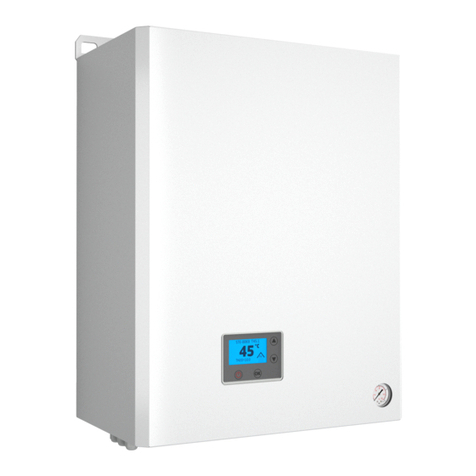
Inta Hiper II V1 User manual

In this document Inta have endeavoured to make all the information and procedures accurate. Inta cannot accept responsibility should it be found that in any respect the information is inaccurate or incomplete as a result of future developments. Installation and Operating Manual Hiper II V1 Heating onlysingle plate HIU e&oe 07/22

Annual servicing is required to ensure that the conditions of the warranty are met. Required Hiper HIU documents. 1. Installation and Operating Manual (this document) 2. Operation and Maintenance Manual (included with the HIU) 3. Commissioning report (included with the HIU) 4. Programming Manual (available on request, contact Inta before commissioning) These instructions describe the installation and operation and fault finding diagnostics of the Hiper II V1 Heat Interface Unit (HIU). For operation of the entire plant, the technical documentation of all the components used such as, boiler, tank, pumps, pipework and valves must be complied with. Inta does not accept any responsibility for the design and performance of the heat network or components outside of the HIU, demarcation being the HIU isolation valves at the connection to the HIU. Installation should only be carried out by a qualified and competent plumbing installer and a qualified and competent electrical installer in accordance with the current Building, Water and Electrical Regulations, Legislation and Standards. Do not start installation until you have thoroughly read and understood all the Installation and Operating Instructions as listed above, and have complied with all safety provisions required. DANGER – immediate risk of physical injury or even death. DANGER – immediate risk of serious damage. IMPORTANT – information critical to the installation or installer. IMPORTANT – information critical to the user. NOTE – useful information regarding the operation or installation of the HIU. SECTION 1 - Important information and introduction Symbols used in these documents Do not tamper or make any alteration to the earthing connections provided as indicated on the casing with the provision of an earthing label! One earthing point is on the outside of the lower casing, underneath the HIU. The other is inside the HIU on the casing backplate. Each earthing connection is provided with a metric Earthing label Earthing Instructions, take note! Page 2 e&oe 07/22

SECTION 2 - Dimensions and components A 585 mm Height B 465 mm Width C 265 mm Depth D 100 mm Pipe Distance E 140 mm Pipe Distance Dimensions Clearances F Sides 30mm G Below 300mm H Above 200mm I In front 50mm D E * clearance of at least 300mm to allow the cover to be removed! Due care must be given by the installer that the cover, heat meter viewing door and components are all accessible! Isolation valves ordered separately as accessory pack HIAC03BVPACK.Page 3 A C B G F H I Inta Description Inta Code HIPER II V1 HEATING ONLY Single Plate HIU with Ista Heat Meter HIPER2SPHOIS HIPER II V1 HEATING ONLY Single Plate HIU with Zenner Heat Meter HIPER2SPHOZE HIPER II V1 HEATING ONLY Single Plate HIU (NO HEAT METER) HIPER2SPHONM e&oe 07/22

Schematic Page 4 SECTION 3 - Schematic e&oe 07/226 7 DH Return 1 11 4 10 9 9 6 8 12 Heating Return 9 DH Flow 2 4 9 Heating Flow 16 15 12345678Drain and vent valvesStrainer with drain valvePocket for heat meter sensorIsolation valvesPressure independent control valvesPlate heat exchanger (PHE)Expansion vesselLow pressure switch910111213141516Temperature sensorsTemporary bypass accessoryHeat meter or temporary spacer pipeSafety relief valveCirculation pumpAutomatic air ventPressure gaugeFilling group

SECTION 4 - Components Page 5 11 14 1. Drain and air venting valves 2. Strainer with drain cap. 3. Pocket for installing heat meter temperature sensor. 4. Isolation Valves (ordered separately). 5. Pressure independent control valve (PICV) and fast acting stepper actuator. 6. Circulating pump for secondary heating. 7. Automatic air vent. 8. Safety pressure relief valve. 9. Low pressure switch. 10. Plate Heat Exchanger. 11. Expansion vessel 8 Ltr. 12. Pressure gauge 13. Temporary bypass or test ports. 14. NTC temperature sensors 15. Heat Meter position or temporary spacer pipe 110mm. 16. Electronic PID controller e&oe 07/22

SECTION 5 - Accessories ACCESSORIES for HIPER 2 TWIN PLATE HIU Part Code Pack of 4 Secondary straight isolation valves. HIAC03BVPACK Pair stand off wall brackets (to allow for pipes to be run behind the HIU). HIAC01SOBPACK Flushing By Pass Kit A for internal installation. (temporary pipe). HI2AKITA Flushing By Pass Kit B for internal installation (Fixed connection to HIU with shut off valve). HI2AKITB Flushing By Pass Kit C (valve and tee fittings) for external installation. HI2AKITC First fix JIG.(use as a template for first fix piping, use with HIACPFFKIT) HI2ACJIG Pack of 4 Secondary straight isolation valves. HIAC03BVPACK Prepayment relay (for billing systems using a 230v signal). HIAC04230KIT Security - anti-tamper fixing screws + driver. HIAC05SSPACK Insulation jacket for HIU isolation valve. ARM022129 Pack of 4 Secondary isolation valves.HIAC03BVPACK Pair stand off wall brackets. HIAC01SOBPACK First Fix Jig Using the Jig allows pipe work to be installed without the HIU. HI2ACJIG.Same Jig is used for all Hiper II HIU so only use the heating connections. Temporary By Pass Kit A HI2AKITA Temporary By Pass Kit C HI2AKITC Temporary By Pass Kit B HI2AKITB X X Page 6 e&oe 07/22

6.1 Before installation read and comply with the following Comply with all safety provisions. Do not tamper with the earthing connections as indicated on the casing. To secure the casing when closing the cover, use the provided M4 screw and washer to ensure earth continuity on the casing.The Installer’s Responsibility - in accordance with Part L of the Building Regulations, all hot and cold water pipes should be labelled and insulated to the current standards. Installation should only be carried out by a qualified and competent plumbing installer and a qualified and competent electrical installer in accordance with the current document Building Regulations, Legislation and Standards. It is the installer’s responsibility to ensure that the place of installation and wall is suitable. An unsuitable location or provision of adequate supplies (Primary Heating and Cold Water mains) will not justify any warranty or fault claim; •The wall must be capable of bearing the weight of the HIU when permanently filled with water.•Locations where access is restricted for maintenance, see page 3. •The HIU is only for WALL MOUNTING in the orientation shown in this manual. •Locations where criminal damage or illegal tampering cannot be reasonably preventable.•Locations where discharge pipe is not able to be safely or legally installed and connected.•Supplies which are not suitably clean, and free from contaminants. •Supplies which contain chemical contaminants. •On site precautions must be made by the installer to protect the unit from builders’ dust and debris. Wall fixing bolts are to be provided by the installer and be suitable to bear the weight of the HIU when permanently full of water. SECTION 6 - Installation 6.2 Consider which installation method is to be used. 1. HIU as delivered to site. 2. HIU and stand off brackets as delivered to site 3. HIU JIG at First Fix Pipe work stage, with the HIU to follow later. 4. HIU JIG and stand off brackets, with the HIU to follow later. 6.3 General installation notes .1. Ensure all pipes are labelled and insulated in accordance with Part L of the building regulations.2.The HIU can only be installed in one orientation, with the heat network connections at the top, and in a vertical position. Before removing the cover turn off the power supply at the mains (fused spur 230v 50Hz). Page 7 e&oe 07/22

SECTION 6 - Installation 6.4 Ensure the chosen installation site is inside the building, weather proofed and provides good access for maintenance, minimum requirements as on page 3. Note where and which pipe connections will be required, and pay attention to where the safety valve discharge pipe will terminate, and ensure this meets all current building regulations and has a continuous fall. 6.5 Making sure the wall the HIU is to be mounted on complies with 5.1, mark up the position for the wall bracket. The position of the HIU is to be on a true vertical plane as in 5.3. Drill and plug the wall, and secure the HIU with suitable wall fixings (not provided with the HIU). Page 8 90o Hang on to the wall bracket hooks and position the HIU against the wall. 6.6 Plumbing Connections A Heat Network Flow B Heat Network Return C 3/4” Heating Flow (radiators or underfloor heating. D 3/4” Heating Return E 1/2” Safety valve discharge F Cold water connection for filling. Installer to provide isolation stopcock. Make connections with HIAC03BVPACK Isolation valves with flat face unions and gasket seals (ordered separately). A B E C D F e&oe 07/22

SECTION 6 - Installation Accessory option - stand off brackets (SOB) 6.8 Stand off brackets create a space behind the HIU that can be used to run pipes in. The stand off brackets are 40mm off the wall allowing for 13mm pipe insulation thickness. First attach the brackets using 4 x fixing screws to the back of the HIU in the matching fixing holes provided. Fit the wall bracket as in 5.6 and per 5.1 Then hang the HIU as in diagram 5.6, but this time using the outer wall bracket hooks. 6.9 Safety valve discharge pipe. The safety valve has a 1/2” F threaded connection for 15mm pipe to be connected to (15mm x 1/2” M compression coupling to be provided by the installer). The discharge pipe should have a continuous fall and conform to BS6798. Where the pipe empties into a drain then that area must be frost free, and consideration as to a trap being included as well as a tundish to ensure any discharge is fully visible. Discharge connection Page 9 6.7 For filling the Heating Circuit for the radiators or UFH, the filling valves and connecting pipes are integral to the HIU. This may be removed while pipe work and isolation valves are made good. Refit when commissioning. On completion of filling the Heating Circuit the temporary con-nection pipe between cold Water supply should be removed. Place safely inside the unit for future filling operations. Cold water filter Electrical connections cable glands. Safety valve discharge connection Temporary connection pipe. Remove after filling. Use outer bracket hooks. e&oe 07/22

SECTION 6 - Installation 6.10 Flushing Bypass Kits - instructions for KIT A and B · See section 6, HIU wiring complete. HIU turned off to close the PICV. · All HIUs on this circuit must be flushed using this method at the same time. · Close the isolation valves as shown, and empty of water through the drain valve into a bowl. · remove test port plugs. · Install the kit adaptors making water tight seal on the O rings of the adaptors. · Fix the flushing pipe in position as shown, tighten the union nuts making a water tight seal with the fibre · washers provided. · Open the isolation valves for system flushing. · When the flushing operation is finished, close the isolation valves as shown below, and empty water through the drain valve again. · Now remove and clean the filter mesh by undoing and removing the filter cap. · Replace the now clean filter mesh, and replace the filter cap. Remove and store the flushing pipe, replace the test plugs and make water tight. Do not over tighten the O rings. · Fill the HIU, ready for commissioning. For External Flushing bypass valves use the above as guidance and follow the instructions included with the valve Adaptors and fibre washers Test ports with plugs Drain Filter cap Flush pipe Page 10 Temporary By Pass Kit A HI2AKITA Temporary By Pass Kit C HI2AKITC Temporary By Pass Kit B HI2AKITB Check Connections! •Flow and Return in correct positions? •All union nuts have been tightened, and a visual inspection expects them to be water tight.•All union nuts inside are tightened, and a visual inspection expects them to be water tight. All isolation valves in the closed position All drain valves and air vent valves are closed. Close the Primary Isolation Valves e&oe 07/22

SECTION 7 - Electrical connections 7 CN1 MODBUS 9600K baud connection. Maximum of 9600 bits per second (bps). 8 ROOM THERMOSTAT—VOLT FREE! 9 DO NOT USE 10 DO NOT USE 11 Pre-payment connection to VOLT FREE supply. 12 Power connection 230V. 7.1 Before electrical connection read and comply with the following. Comply with all safety provisions. Installation should only be carried out by a competent electrical installer and the installation conform to all IEE regulations 7.2 The installer is to provide a 230vAC 3 amp fused supply as per BS EN 7671:2008. Entry for cables is provided by 3 x cable glands located beneath the HIU ( at the rear, LHS). Live, neutral and earth connections as per the diagram below. 7.3 Room thermostat connection as per the diagram below. This is a 2 core cable connection and VOLT FREE. The room thermostat switching position is NORMALLY OPEN (though this can be changed to normally closed in the installer level programming of the controller which is covered in the separate programming manual). Note that the Room thermostat switching must be VOLT FREE !! Note that the billing connection for pre-payment function must be VOLT FREE !! Electrical connections access panel; remove securing screws to enter Isolate all electrical supplies before removing the access panel ! FUSE Note Internal fuse specification 630 mA glass fuse Page 11 e&oe 07/22

Section 8 - sequence of first power up and user menu. OK (set) OK ON /OFF UP and DOWN arrow buttons On first power up, the controller will perform a check on all connected components. If all is OK, it will automatically proceed to the set up menu. If a fault or wiring error is detected, a warning symbol will appear until the error is corrected. START HERE The correct date and time is required for recording a history of diagnostic codes, or timed functions (see page 15). 5b SET TEMP RADIATOR 60 C Factory settng for radiators is 60C. Press OK or change with the up and down arrow buttons to increase or decrease the heating flow temperature. Press OK to set. Drying starts at the minimum temperature. 25°C as factory setting for 3 days then rises to the maximum factory set temperature (40°C as factory set) for 4 days. The function can be stopped by pressing the OFF button. Controller screen looks like this, now in standby mode. SETRT=46.5 OK First start up sequence to ensure the selection of radiators or UFH. SET HEATING RADIATOR Change to YES using the UP or DOWN button to initiate the floor drying for a new UFH system. SELECT FLOOR HEATING or RADIATOR UFH is the factory default. Use the arrow UP/DOWN arrow buttons to change to RADIATORS 7. ENGLISH, ITALIANO, FRANCAIS, NEDERLAND or DEUTSCH. Factory setting for UFH is 30°C. Press OK or change with the UP and DOWN arrow buttons to increase or decrease the heating flow temperature. Press OK to set. SET LANGUAGE ENGLISH 2. SET DATE 01/01/21 1. 3. SLAB DRYING STOP=167h 59m TFLOOR = 24.5C SET HEATING FLOORHEATING SLAB DRYING NO 6. 5a. SET TEMP FLOOR 30 C 4. SET TIME 09.30 6a. UP and DOWN buttons - use to increase or decrease a value or number. OK button - to confirm and set a value or number. ON / OFF button will turn off the HIU. The unit will not be in standby mode. Heating and frost protection functions are OFF. User Operation. Screen symbol for radiator heating ON Screen symbol for UFH heating ON When in use the SET temperature will be shown on the screen. The screen does not show room temperature. Page 12 e&oe 07/22

SECTION 9 - The HIU features All features and functions can be accessed in the installer level programming. How to access, and a list of all the parameters which can be programmed are in a separate document that is not to be left with the end user as misuse of these set parameters my cause the HIU to not operate as efficiently as commissioned. Refer to the Installer Controller Parameter Settings Guide, available from Inta or the supplier request. •Language options. •UFH or Radiator Heating. •UFH floor drying (slab drying)* •Minimum temperature limiting HTG Maximum temperature limiting HTG•Optimised heating (uses less heat as the HTG temperature nears the set point) •Flow limiting in HTG mode •Frost protection. •PWM pump control. •Manual switching of the pump. •Prepayment operation and shutting down of the HIU when out of credit. •Manual mode for the PICV actuator. •Room thermostat switching options for normally open or normally closed switching. Features available in the HIU Controller Check the temperature sensors are clipped securely to the pipes for accurate control. All the sensors are colour coded for ease of identification and checking that the sensor is in the correct position. RED = Primary FLOW BLUE = Primary RETURN WHITE = Heating FLOW GREY = Heating RETURN The Controller Programming Guide is only for the use of the installer or commissioning engineer, and under no circumstances should be left with the user or home owner. Incorrect parameter programming may result in inefficient performance or error code diagnostics which prevent the HIU operating as required. *SLAB DRYING (first time of applying heat to the screed/floor). Select YES to initiate the floor drying for a new UFH system Drying starts at the minimum temperature (25°C as factory set) for 3 days then rises to the maximum factory set temperature (40°C as factory set) for 4 days => 7 days total. These minimum and maximum temperatures can be reset respectively with parameter 03 and parameter 12 in the installer menu. The screen shows the time left for this operation. The function can be stopped by pressing the OFF button. Programming the HIU Controller. Any changes to the factory settings should be carried out during commissioning. Details of programming parameters are to be found in the Controller Programming Guide. Contact Inta to request the Controller Programming Guide. This document is not to be left with the HIU or the occupier of the home! This document is available on request from your Inta Specification Manager involved with this installation project. Alternately contact by; Inta website https://intatec.co.uk/contact-us/ Phone 01889 272181 ask for HIU Technical Support or HIU Service Desk. Page 13 e&oe 07/22

SECTION 10 - Controller factory settings Description /parameter Factory Set Start temperature floor drying. 25 Factory set temperature for underfloor heating (UFH). 30oC Factory set temperature for radiators heating. 60oC Select heating type (FLOOR HEATING or RADIATORS) FLOOR HEATING Set minimum temperature for underfloor heating (UFH). 20oC Set maximum temperature for underfloor heating (UFH). 40oC Set minimum temperature for radiator heating. 40oC Set maximum temperature for radiator heating 65oC Optimised heating function switch ON (YES) or OFF (NO). NO Set ∆T heating optimized function for UFH (∆T opt. UFH). 5oC Set ∆T optimized heating function for radiator heating 10oC Set time period for measuring the ∆T in optimized heating function in minutes. 25 Limiting the primary flow for Heating (max travel of the stepper motor in heating mode) value 99 % valve fully closed. 70 Set max. primary return temperature limit. 60oC Select pump protection. If the pump is not run after 24 hours, the pump is turned on, this prevents the pump from seizing during long periods of no usage). NO Set the time for running the pump during the pump protection programming function in minutes. 2 Set frost protection. Temperature is measured from the heating return temperature sensor. 3oC Set PWM function (00 = OFF). 99 is on max speed modulation from external source. PWM cable provided only as an accessory. 00 Manual operation of heating pump (overrides room thermostat). NO Select type of contact room stat connection switching (N.OPEN = Normally open / N.CLOSE = normally closed) N.OPEN Description/parameter Factory Set Prepayment - select Prepayment NO or YES. ‘Pay as you go’( PAYG). Connected to a Billing Provider by a VOLT FREE connection. NO PICV ACTUATOR - manual operation stepper motor PICV 00 = AUTO. (Setting 01 = FULLY CLOSE Setting 02 = FULLY OPEN). AUTO PUMP - manual operation. 00 = AUTO. (Setting 01 = PUMP ON Setting 02 = PUMP OFF) AUTO Language. English SLAB - start the slab drying function. NO Reset to Factory Settings. Note if operating as a single plate HIU - reset parameter 60! NO Diagnostics (display shows operation, temperature, valve opening steps). NO Programming HIU Controller. Any changes to the factory settings should be carried out during commissioning. Details of programming parameters are to be found in the Controller Programming Guide. This document is available on request from your Inta Specification Manager involved with this installation project. Alternately contact by; Inta website https://intatec.co.uk/contact-us/ Phone 01889 272181 ask for HIU Technical Support. ∆T = Temperature differential value Page 14 The Controller Programming Guide is only for the use of the installer or commissioning engineer, and under no circumstances should be left with the user or home owner. Incorrect parameter programming may result in inefficient performance or error code diagnostics which prevent the HIU operating as required. e&oe 07/22

SECTION 7 - The HIU Controller first power up and set up SECTION 11 - Fault and Error Codes / Fault finding guide Diagnostics - Fault code definitions. A fault code informs that the controller has diagnosed a fault in one of the HIU’s components. When any fault occurs, the relevant code will be displayed on screen.code Cause Effect Remedy F1 Primary flow temperature sensor is short circuit or broken circuit, or disconnected. The HIU will not operate in Heating mode. Check that the sensor cable plug connection is good, and if OK then check the connection inside the controller. If this doesn’t clear the F1 code, then replace the sensor. The F1 will clear and return to normal operation. F3 Heating flow temperature sensor is short circuit or broken circuit, or disconnected. The HIU will not operate in Heating mode. Check that the sensor cable plug connection is good, and if OK then check the connection inside the controller. If this doesn’t clear the F3 code, then replace the sensor. The F3 will clear and return to normal operation. F4 Primary return temperature sensor is short circuit or broken circuit, or disconnected. The HIU will not operate in Heating mode. Check that the sensor cable plug connection is good, and if OK then check the connection inside the controller. If this doesn’t clear the F4 code, then replace the sensor. The F4 will clear and return to normal operation. F5 Heating return temperature sensor is short circuit or broken circuit, or disconnected. The HIU ‘heating optimisation’ function is disabled as this sensor controls the heating return temperature . Check that the sensor cable plug connection is good, and if OK then check the connection inside the controller. If this doesn’t clear the F5 code, then replace the sensor. The F5 will clear and return to normal operation. F7 Either the pressure in the heating system is too low or the pressure switch is faulty. The HIU will not operate in Heating mode. Check the system pressure on the gauge on the HIU. The pressure switch will cut out at 0.15 bar. Refill system to 1.2 bar. Resets normal operation after 30 seconds. If low pressure is not the issue, replace the pressure switch. F8 The controller is recognising from the feed-back from the electrical connection that the rotation of the pump is not what it is expected to be. The HIU will not operate in Heating mode. Check wiring connections to the pump. Check pump for red LED lights signifying a fault. Check PWM is not set as ON in parameter 24. Setting must be 00 as factory set.* Only consider replacing the pump head once everything else has been checked Check water quality which is usually the cause of a premature pump failure The Controller Programming Guide is only for the use of the installer or commissioning engineer, and under no circumstances should be left with the user or home owner. Incorrect parameter programming may result in inefficient performance or error code diagnostics which prevent the HIU operating as required. Page 15 A Fault code is not displayed but the following has occurred. •No Room Heating •Radiators are COLD. •Under Floor Heating is installed Floor is COLD. •Check the ambient temperature. Is the reason that the room thermostat setting is too low to switch on the heating? •System low pressure. Has the safety valve discharged? Check system pressure and top up if necessary. •Air blockage in the radiators. •Check the Circulating Pump (see LED lights on the pump which can warn of a problem or a fault). Is the pump fully operational? •Is the controller set up correctly? See Installer settings. •Is the Room thermostat wired correctly? Is it working? •Check that the communal heating is supplying heat to the unit. •Check then that the isolation valves to the unit are open. •Is the Bypass Valve open on the valve above the HIU? e&oe 07/22

SECTION 7 - The HIU Controller first power up and set up SECTION 11 - Fault and Error Codes / Fault finding guide code Cause Effect Remedy E1 The measured primary temperature is lower than the set point temperature is for heating so the HIU will not be able to achieve the set temperature. This is after approximately 60 seconds of flow. The function is re-enabled when the primary exceeds the setpoint temperature. Check the set point in the controller, adjust if the set point is set higher than the design supply temperature. Check that the primary temperature probe is correctly connected to the primary pipe. When the primary temperature and set point are aligned, the error code E1 automatically disappears. E2 In installations where Radiators are at very high temperatures, then this is a warning that the return temperature is higher than the maximum allowed in parameter 20. As this is a safety function, the PICV closes until the sensor on the primary return sees a temperature drop of 10C below the parameter 20 set point for maximum. Check parameter 20 is set correctly, if too low, reset this at 5C higher than secondary heating flow set temperature. Check the temperature probe is positioned correctly. Reset (turn power on and off) to recalibrate the PICV actuator. E3 The controller is recognising and warning that the HIU performance is not as the algorithm predicts. The energy transfer is poor, and the HIU is not delivering heat as it should be. Heat transfer is inefficient, heating capacity reduced and temperature control unstable. If signs of blockage it could be the strainer is blocked or the PHE is partially blocked with lime scale. Check PICV fully open and check flow on the heat meter. Low flow value would prove that a blockage of some sort is the issue. E5 Heating is not reaching the set point so is performing poorly or not at all. Heating stops after 20 minutes and shows the E5 code. Resets after 30 seconds Or Error LEDs on the pump? Power ON and OFF at the mains switch, this allows the PICV to recalibrate, and in doing this will allow a small flow into the PHE, which then proves the PICV and Diverter not at fault. Check the following possibilities. - Primary temperature is too low? - Is the set temperature on the controller higher than the incoming primary (network) temperature and temperature is impossible to reach? Rest set the temperature so it is 10C lower than the primary. - PICV blocked / strainer blocked? - Diverter in the wrong posion? E6 Temperature information from the heating temperature sensors is wrong or unusual. Return temperature is too high with no apparent control being seen. This error code is showing that either; 1.The heating temperature sensors have been wrongly positioned with the flow on the return and the return on the flow, change them to their correct position. 2.The installer has not connected the primary connections correctly, with the flow connected to the return connection. Check temperatures. E7 The heating return temperature is too high and the HIU is warning the operator. Various causes may be considered, example all TRVs may be closed with only 1 x small radiator open, but the room thermostat is still calling for heat. Various causes may be considered, example all TRVs may be closed with only 1 x small radiator open, but the room thermostat is still calling for heat. The return temperature is much too high, so the HIU ceases .The effect is that the controller shuts down the pump before re-starting again after 10 minutes. The E7 will automatically reset itself aſt er 10 minutes. Attention should be paid to the set up of the heating radiators and controls. Is the room thermostat positioned correctly to turn off before all the TRVs shut down? Is the radiator circuit balanced correctly at the radiator valves? E7 may occur under certain test conditions where unnatural operating conditions are forced. E8 The PICV actuator cable has been disconnected from the controller or there’s a failure on the actuator itself. The E8 code appears on the screen. Heating is no longer available. To avoid over heating risk , when the HIU detects a heating flow temperature 10°C above setpoint for more than the programmed time interval (90 seconds factory set, adjustable up to 210 seconds) the HIU will shut down and show an E8 error code. Pump will switch off. Allow the unit to cool down first! Check PICV actuator connection, and that the valve stem pin is not jammed (free if possible). Power OFF then ON again, check for movement in the actuator stem. Replace the actuator if found to be seized. Replace the valve cartridge if found to be seized. Diagnostics - Error code definitions. When an error code is displayed, the controller is warning of unsuitable operating conditions that may be causing the HIU to operate inefficiently or possibly, not at all. If left in that state, these conditions could become a safety issue. Page 16 e&oe 07/22

SECTION 7 - The HIU Controller first power up and set up SECTION 11 - Fault and Error Codes / Fault finding guide Danger - 230v ! NO HEATING Is a warning symbol displayed on the controller screen? Heating ON! Is the primary FLOW rate and temperature sufficient? YES NO YES Is the room thermostat is calling for heat. Set room thermostat and turn heating on Symbol for heating appears and pump on Does the heating symbol show on the display when the room thermostat is calling for heating? NO YES Check the room thermostat wiring to the controller is as per page 12. If 230 v has been applied to the room thermostat connections then the controller maybe damaged beyond repair and will have to be replaced. Warranty will not cover this! *see Installer Controller Parameter Settings Guide YES Check room thermostat wiring. N/open or N/closed switching? See installer parameter 26*. Check room thermostat by over ride on parameter 25* (manual heating). Replace room thermostat if found faulty. Vent the system of air. Rectify. Problem is not the HIU. NO Replace pump Pump - are LEDs flashing red? YES NO fault code displayed See fault code description and check if the programming is correct* If prepayment used, is it in CREDIT? If a fault code is showing* rectify the fault according to the code description. * Have the ‘Controller Programming Guide at hand! Page 17 e&oe 07/22

SECTION 7 - The HIU Controller first power up and set up SECTION 11 - Fault and Error Codes / Fault finding guide Power on, HIU operating normally YES NO NO POWER? Comply with all safety provisions. Installation and maintenance can only be carried out by a qualified and competent plumbing installer and a qualified and competent electrical installer in accordance with the current document Building Regulations, Legislation and Standards. SAFETY! – before any electrical work or maintenance ensure that the electrical supply is isolated. DANGER – immediate risk of physical injury or even death. Check that the volt free connections for room thermostat or Prepayment have NOT been wired to 230V Is there power to the fused spur connecting to the HIU? Check power supply and Fuse feeding to the HIU. Fused spur requires a 13A Fuse all correct? Turn off the potential power supply using the isolation switch fused spur. Check Fuse and wiring within the HIU. 6.3 AMP Glass Fuse NO If 230 v has been applied to the room thermostat connections then the controller maybe damaged beyond repair and will have to be replaced. Warranty will not cover this! YES Check power is on the HIU electronic controller. Remove the installer panel and check Live and Neutral connections. Are they connected? YES Power is at the connections to the controller, but the controller screen is blank. OMake good the electrical connections to the HIU controller. Order a HIU new controller and replace NO YES YES YES Page 18 e&oe 07/22

SECTION 7 - The HIU Controller first power up and set up SECTION 12 - Pump. SECTION 7 - The HIU Controller first power up and set up Pump operating and Fault LEDs Page 19 e&oe 07/22

SECTION 7 - The HIU Controller first power up and set up SECTION 13 - Technical Specification DH maximum pressure 16 bar DH maximum temperature 85° C DH maximum pressure differential. 4 bar HTG maximum working pressure 2.5 bar HTG safety valve setting 3 bar HTG maximum temperature 75° C HTG - radiators temperature adjustment 30°C to 75°C UFH - underfloor heating temperature adjustment 20°C to 50°C HTG maximum output (85C at 1330 ltrs/hr) 29kW HTG minimum output 1kW Pump - Grundfos UPM3 (K) FLEX AS 15-75 CIAO2 (GFNJB) Heating pump nominal head capacity 7.5 kPa Electrical supply 1 ph 50Hz 230v Control method Electronic PID controller with fast acting stepper / PICV. Plate Heat Exchanger Stainless steel—insulated Wras approved Expansion Vessel 8 Ltr Casing Fully insulated steel backplate and cover Dimensions 585mm H x 465mm W x 265mm D Heat meter options Zenner C5 MID compliant 1.5 qp M3/hr 110mm Filters 1) Primary 2) Htg 800 micron Internal pipework copper Isolation Valves with flat face union connection NOT included, order separately from ACCESSORIES General Technical Page 20 e&oe 07/22
Table of contents
Other Inta Heating System manuals
Popular Heating System manuals by other brands

VOKERA
VOKERA Linea User instructions
Lindab
Lindab PENNY QN Instructions for installation, use and maintenance manual
OSTBERG
OSTBERG HERU 400 Series Installation

ubbink
ubbink Ubiflux Vigor W225 installation instructions

flowair
flowair EX LITE Technical documentation operation manual

HEATIZON SYSTEMS
HEATIZON SYSTEMS Gutter Melt SR Design & Installation Manual
