3
ORIGINAL INSTRUCTIONSVES Andover Ltd Eagle Close Chandlers Ford Ind. Est Eastleigh Hampshire SO53 4NF
Tel: 08448 156060 Fax: 02380 261204 E-mail: vesltd@ves.co.uk Web: www.ves.co.uk
Installation, Operation and Maintenance Manual
®
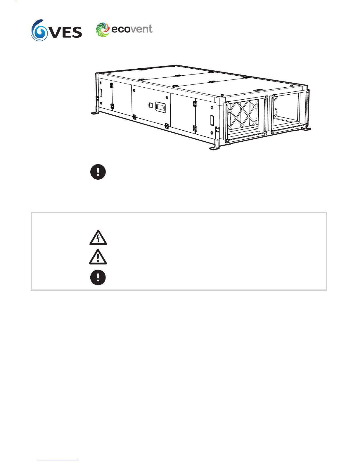
EVCHeat Recovery Unit
Immediately upon receipt of goods, check for possible damage in transit paying particular
attention to fan impellers, coil connections and unit casing. Prior to installation please check
to ensure alignment and smooth rotation of the impeller after transit. Also check to ensure that
any ancillary items are included. These will normally be supplied fitted or, in the case of small
items, taped to the unit.
In the event of any damage having occurred or if any item is found to be missing, it is essential
to inform VES Andover Ltd. within 7 days of delivery quoting sales order number and the unit
type, as found on the unit nameplate. After this period, VES would be unable to accept any
claim for damaged or missing goods.
The entire system must be considered for safety purposes and it is the responsibility of the
installer to ensure that all of the equipment is installed in compliance with the manufacturer’s
recommendations, with due regard to the current HEALTH AND SAFETY AT WORK ACT and con-
forms to all relevant statutory regulations.
Where a unit is installed so that a failure of components could result in injury to personnel,
precautions should be taken to prevent such an injury. If the unit is installed where there is a
reasonable possibility of persons or objects coming into contact with the impeller whilst
operational, a guard should be fitted or steps taken to prevent this. It is the installer’s
responsibility to ensure that access panels are not obstructed in any way and safe working
access for maintenance must be provided in accordance with Health and Safety and Building
Regulations. For confirmation of required access please see the appropriate unit outline
drawing.
Consideration must also be given by the installer for adequate illumination of the unit location
in order for safe maintenance. Further consideration should be given to the unit’s position and
secured into place as appropriate. This is especially important with external mounting as the
wind and elements may effect the overall stability and safety of the unit.
Mounting hangers, door furniture, isolators etc. extend beyond the casework and so are
vunerable to accidental damage. Take necessary precautions so as not to cause damage whilst
handling the unit.
The weight of each unit/section is specified on the outline drawing and the total unit weight
will be displayed on the unit inspection label. When lifting the unit using a fork lift truck
ensure the whole unit is supported by the full length of the forks. It may be necessary to use
fork extensions to fully support the unit properly. The centre of gravity may be offset from the
centre of the unit; this needs to be taken into consideration when lifting the unit.
Handle with care. Failure to fully support the unit during lifting may result in damage to the
unit casework Handles, lids, housings and coil connections must NOT be used as lifting points.
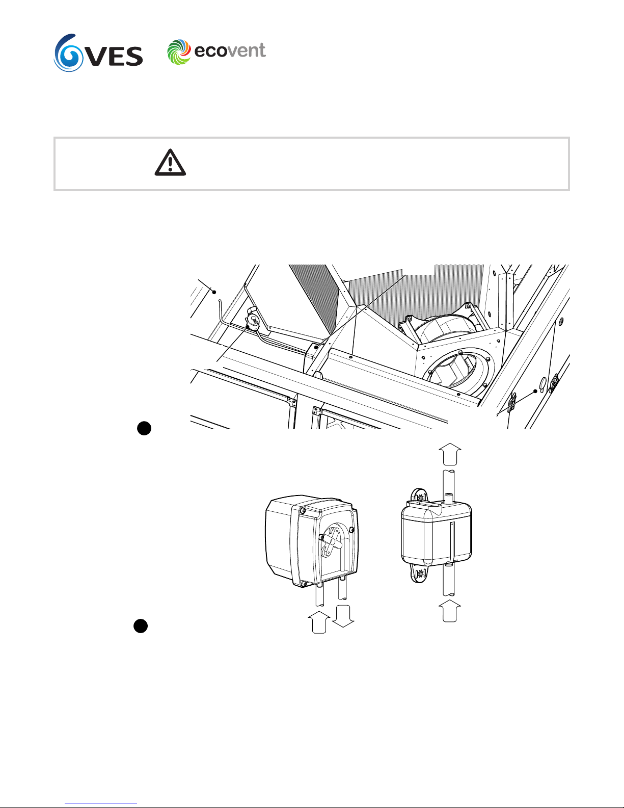
Units are to be rigged and lifted using spreaders, taking
into account the weight of the unit, and lifting gear should
be arranged so as not to bear on the casework see right.
Caution
Receipt of Goods
& Handling
Installation
3
Lifting Detail
Fig.