INTAP ZBELT-09CAN User manual

ZBELT-09CAN
User Manual
Version 0.3 z 2023-02-04

2 ZBELT-09CAN system –user manual
General information
The ZBELT-09 system is designed to signal the lack of fastening of seat belts in special
vehicles not equipped with such a system at the factory. A characteristic feature of the system
is wireless communication between devices in the 868MHz band. The system contains two
types of devices:
•ZBELT-09CAN basis module installed in vehicle
•ZBELT-0F seat module installed in the armchair.
A maximum of 8 seats can be assigned to the driver module. The occupancy status of the
seats as well as the fastening status of the seat belts is sent via the CAN bus. The device is
equipped with a button used to pair the seat modules.
Base module - Installation in the vehicle
The driver module is installed in a place that provides the possibility of connecting the power
supply and CAN BUS of the vehicle control system. Care should also be taken to ensure that
this place provides the possibility of radio communication with the seat modules. It is
unacceptable to place it in a place that shields electromagnetic waves, i.e. in a metal
housing.
The module is fixed with two screws with a maximum diameter of 5mm.
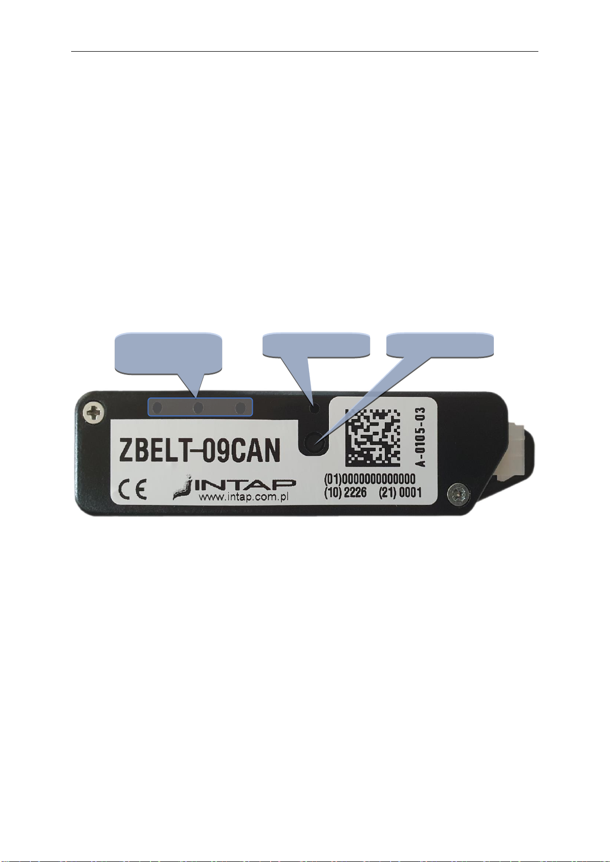
Pairing button
Status LED
LED showing
pairing position

ZBELT-09CAN system –user manual 3
Base module –Electrical connection
The device is equipped with a male 6-terminal MINI-FIT connector.
ZBELT-09CAN Signal outputs at the connector
PIN
Function
Remarks
1
Ground
2
+12V/+24V Power
Constant power supply through 0.5A fuse
3
Positive input
Optionally +15 signal
4
CAN - H
CAN High signal
5
CAN - L
CAN Low signal
6
Negative input
Optionally speed signal –ground active
For proper operation of the base module, it is required to connect a constant power supply
available after removing the ignition key, ground and CAN communication lines.

4 ZBELT-09CAN system –user manual
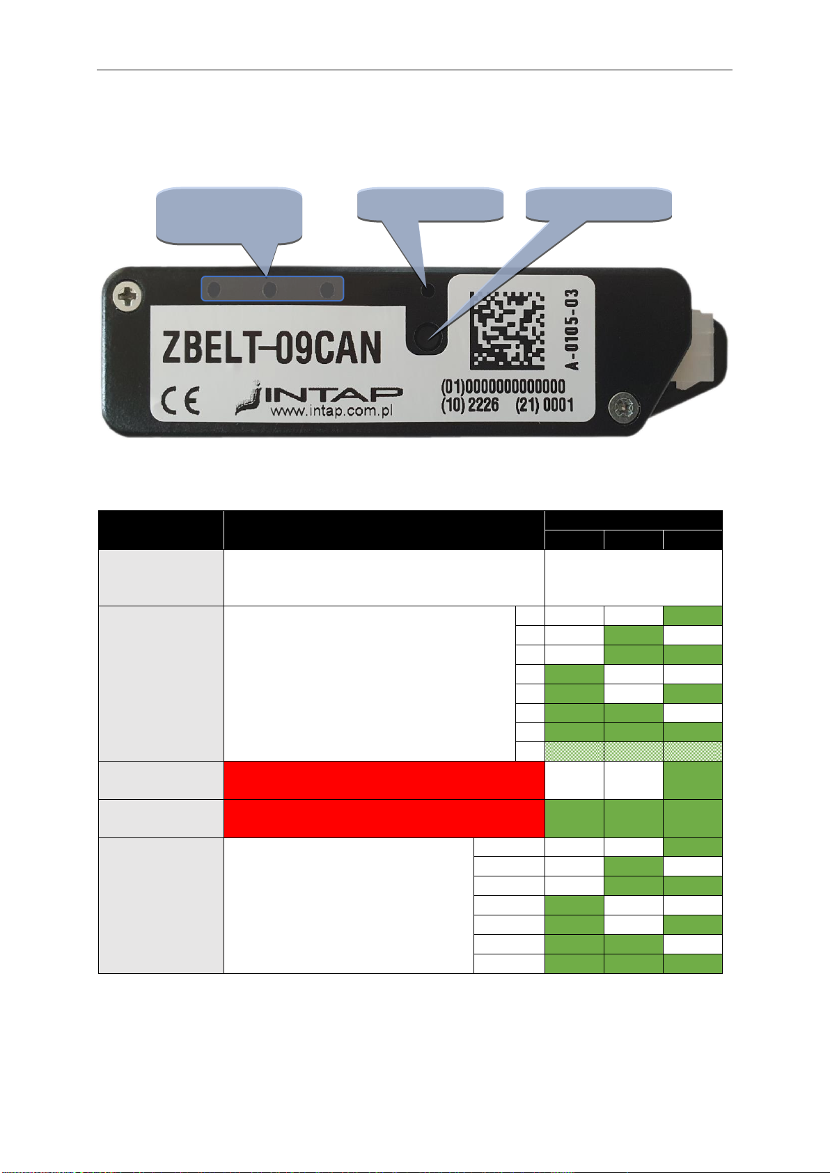
Base Module –Device Status
State
status LED
Pairing LEDs
2
1
0
Normal
operation
Short red flashes = presence of power
Short green flash = received radio frame
Dark
Pairing
Short red flashes = presence of power
Short green flash = received radio frame
1
ON
2
ON
3
ON
ON
4
ON
5
ON
ON
6
ON
ON
7
ON
ON
ON
8
ON
ON
ON
Lack of
Pairing
Solid red
ON
Module
reset
Solid red
ON
ON
ON
CAN BUS
Mode select
GREEN Fast blinking
Mode 1
ON
Mode 2
ON
Mode 3
ON
ON
Mode 4
ON
Mode 5
ON
ON
Mode 6
ON
ON
Mode 7
ON
ON
ON
The module resets whenever the power is switched on, but it can also be caused by a problem with
CAN communication (no frame confirmation) or a module hanging causing the Watchdog system to
work.
Pairing button
Status LED
LED showing
pairing position
LED2 LED1 LED0

ZBELT-09CAN system –user manual 5
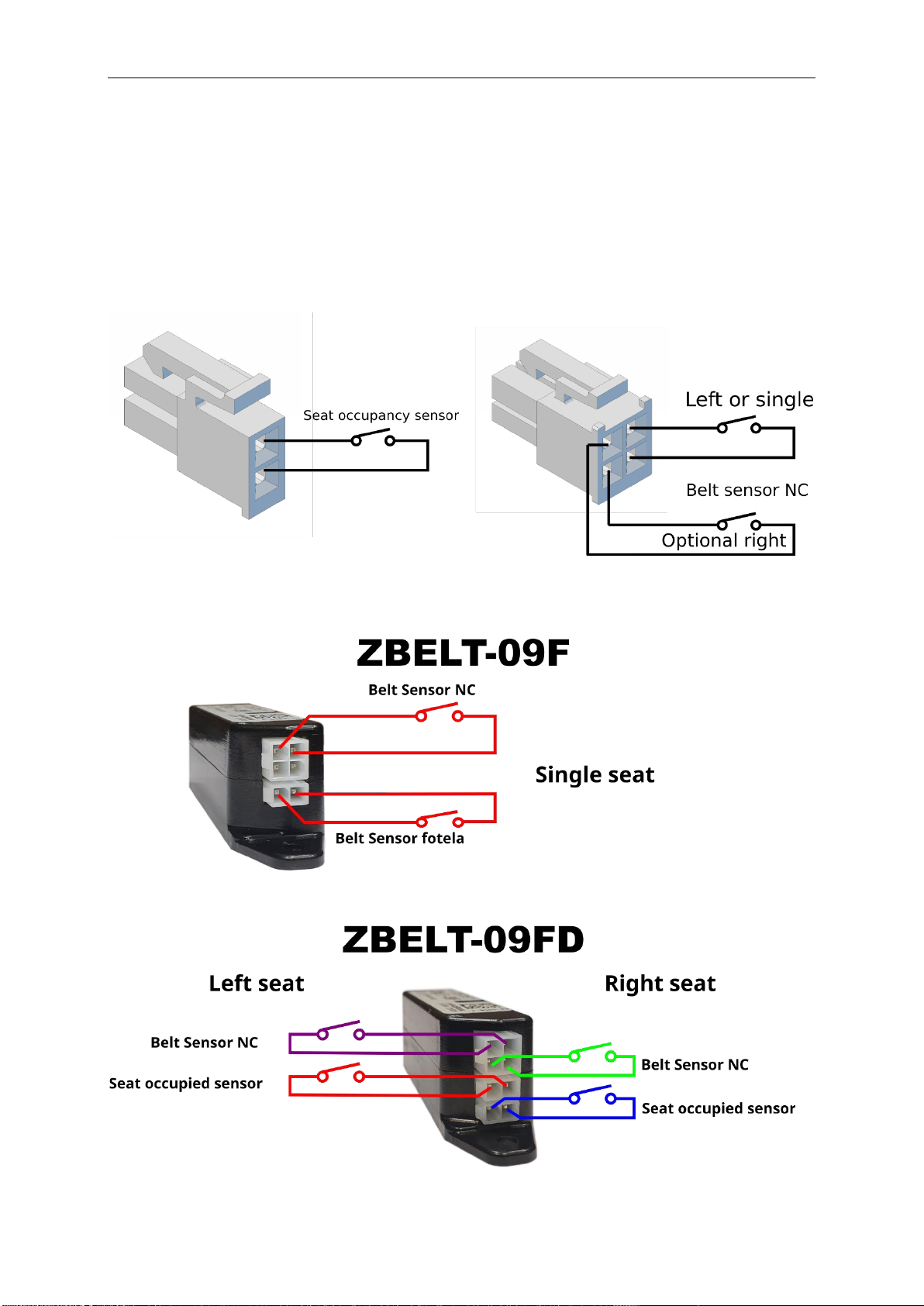
Seat module connections
There are two sensors connected to the seat module:
•Seat occupancy pressure sensor - closed when the seat is occupied
•Micro-switch located in the safety belt buckle –short when the belt is not fastened

6 ZBELT-09CAN system –user manual
Seats pairing process
In order for the system to work properly, it is required to assign the seats to their numbers in
the system so that the display system can present them properly.
.
1. If you pair an seat in a new location, the system will automatically free up its old
position. Multiple pairing of the same chair in subsequent positions will result in their
erasing one by one.
2. Pairing the seat with another base module will erase the pairing with the current module.
So the chair module can be paired with only one base.

ZBELT-09CAN system –user manual 7
Replacing battery in the seat module
The seat module is powered by a 3,6V lithium battery placed inside the module. The battery should
last at least two years. You need to replace it when the driver's panel indicates low battery by
flashing the seat belt symbol.
You should use ER14505 battery type.
Please note that it is NOT popular 1.5V AA battery.
Using other battery will damage the module!
To replace battery you have to open seat module. Please follow instructions below.

8 ZBELT-09CAN system –user manual
Technical data
Seat module ZBELT-09F
–rated supply voltage 3,6V –lithium battery ER14505
–power consumption ~1.4uA in waking time mode
–transmiter power ~8dBm ERP
–Radio frequency 868,5MHz
–type of modulation LORA
–battery life >4 years
Moduł bazowy ZBELT-09CAN
–rated supply voltage 12V lub 24V
–power consumption ~4mA@12V w czuwaniu
–transmiter power ~11dBm ERP
–Radio frequency 868,5MHz
–type of modulation LORA
The housings of the ZBELT-09CAN and ZBELT-09F modules are identical:

ZBELT-09CAN system –user manual 9
Installer settings –CAN Bus mode select
The ZBELT-09CAN device can cooperate with various control systems with which the bodybuilder
equips the vehicles. In order for the communication to work properly, it is necessary to select the
speed of the CAN bus, the type of identifier (11/29bit) and frame IDs. The ZBELT-09 device can
operate in one of 7 modes.
Setting
number
Bus speed
ID mode
FRAME IDENTIFIERS
SEAT_OCCUPATION
ZBELT_COMMAND
ZBELT_INFO
1
250kbit
11bit
0x75
0x76
0x77
2
250kbit
29bit
0x18F0075
0x18F0076
0x18F0077
3
500kbit
11bit
0x75
0x76
0x77
4
500kbit
29bit
0x18F0075
0x18F0076
0x18F0077
5
Do not use ! Reserved for future use.
6
7

CAN frames format
Data
SEAT_OCCUPATION
Send Addres / ID
SEAT_OCCUPATION_ID
CYCLE
1000ms
Speed
Length
5 bytes
Transmision direction
ZBELT-09CAN -> USER SYSTEM
Decryption
Bit 7
Bit 6
Bit 5
Bit 4
Bit 3
Bit 2
Bit 1
Bit 0
Byte 0
Green LED (seat occupied, belt fastened)
Seat8_green
Seat7_green
Seat6_green
Seat5_green
Seat4_green
Seat3_green
Seat2_green
Seat1_green
Byte 1
Red LED (seat occupied, belt not fastened)
Seat8_red
Seat7_red
Seat6_red
Seat5_red
Seat4_red
Seat3_red
Seat2_red
Seat1_red
Byte 2
Pairing Status (1=paired, 0=free)
Seat8_pair
Seat7_pair
Seat6_pair
Seat5_pair
Seat4_pair
Seat3_pair
Seat2_pair
Seat1_pair
Byte 3
Low Battery warning
Seat8_LBW
Seat7_LBW
Seat6_LBW
Seat5_LBW
Seat4_LBW
Seat3_LBW
Seat2_LBW
Seat1_LBW
Byte 4
Pairing in progress seat number
8bit value - 0x0=not pairing, 0x01=waiting for seat 1 pairing, 0x02=waiting for seat 2 pairing………
UWAGI
NOTES
Data
PAIRING
Send Addres / ID
ZBELT_COMMAND_ID
CYCLE
send once
Speed
Length
1 bytes
Transmision direction
USER SYSTEM -> ZBELT-09CAN
Byte 0
Pairing order for seat no …
8bit value -
0x00 = stop pairing,
0x01 = pair seat 1,
0x02 = pair seat 2,
0x03 = pair seat 3,
……
0x08 –pair seat 8
UWAGI
NOTES
Po odebraniu ramki urządzenie oczekuje na parowanie modułu fotela na pozycji którą otrzymało. Po sparowaniu modułu wraca do normalnej pracy. Parowanie następnego fotela
wymaga kolejnej ramki.
After receiving the frame, the device waits for the chair module pairing in the position it received. After the module is paired, it returns to normal operation. Pairing the next seat
requires another frame.

ZBELT-09CAN system –user manual 11
Data
PAIRING ERASE
Send Addres / ID
ZBELT_COMMAND_ID
CYCLE
send once
Speed
Length
7 bytes
Transmision direction
USER SYSTEM -> ZBELT-09CAN
Byte 0
0xFF
Byte 1
0x45 = ‘E’
Byte 2
0x52= ‘R’
Byte 3
0x41= ‘A’
Byte 4
0x53= ‘S’
Byte 5
0x45= ‘E’
Byte 6
0x00
UWAGI
NOTES
Aby wykasować parowanie należy wysłać ramkę 0x76 zawierającą 7 bajtów danych: 0xff „ERASE” 0x00
To erase all paired seats, send the 0x76 frame containing 7 data bytes: 0xff "ERASE" 0x00
Data
GET INFO
Send Addres / ID
ZBELT_COMMAND_ID
CYCLE
send once
Speed
Length
1 bytes
Transmision direction
USER SYSTEM -> ZBELT-09CAN
Byte 0
0xFE
UWAGI
NOTES
Urządzenie jednorazowo wyśle w odpowiedzi ramkę ZBELT_INFO
Device will send one ZBELT_INFO frame.

12 ZBELT-09CAN system –user manual
Data
GIVE VERSION
Send Addres / ID
ZBELT_INFO_ID
CYCLE
send once
Speed
Length
7 bytes
Transmision direction
ZBELT-09CAN -> USER SYSTEM
Byte 0
CAN board firmware version
Byte 1
TRX PCB firmware version
Byte 2
TRX Frequency calibration factor
Byte 3
LSB
0xF1
4 bytes serial numer
i.e. 23030001 = 0x015F68F1
Byte 4
0x68
Byte 5
0x5F
Byte 6
MSB
0x01
UWAGI
NOTES
Ramka do celów informacyjnych. Implementacja w systemie użytkownika nie jest konieczna
This frame is for information purposes only. Implementation in user system is not necessary.
This manual suits for next models
1
Table of contents
Popular Automobile Accessories manuals by other brands

Safe Fleet
Safe Fleet Prime Design VBR-TC11B Assembly instructions

ECS Electronics
ECS Electronics TO-245-BHU Fitting instructions

Mont Blanc
Mont Blanc BU2 Fitting instructions

CARRYBOY
CARRYBOY CB-744-CFTC installation manual

Cruz
Cruz 925-71 Series Assembly instructions

Digital Barriers
Digital Barriers EDGEVIS HD-IP450 installation guide