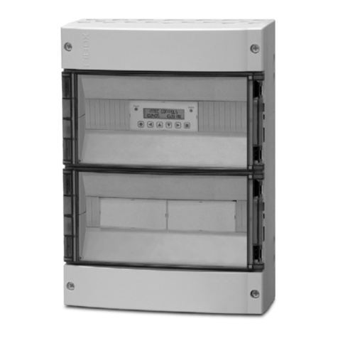
Intec PolyGard LGC/LG2-04 User manual

Customer Services (858) 578-7887 & (888) GO INTEC
INTEC Controls, 12700 Stowe Dr., Suite 100, Poway, CA 92064
Fax (858) 578-4633 & (888) FX INTEC
www.inteccontrols.com
Specication subject to change without notice.
Printed in USA 131119
November 19, 2013 – Revision
Polygard® is a registered trademark of MSR LGC/LG2-04
PolyGardController LGC/LG2-04
Multi-Point Controller
Serial Number – S00
User Manual
August 11, 2006
Specifications subject to change without notice. | USA 131119 | Page 1of 30
12700 Stowe Drive, Suite 100, Poway, CA 92064 | Ph: (858) 578.7887 & (888) GO.INTEC | relevantsolutions.com/inteccontrols
LGC-LG2 – UserManual
Polygard® is a registered trademark of MSR | LGC/LG2-04
12700 Stowe Drive, Suite 100, Poway, CA 92064 | Ph: (858) 578.7887 & (888) GO.INTEC | relevantsolutions.com/inteccontrols
PolyGard®is a registered trademark of MSR-Electronic GmbH | LGC/LG2-04
January 04, 2016 – Revision
February 11, 2020 – Revision
INTEC Controls | 12700 Stowe Drive, Suite 100, Poway, CA 92064 | Ph: (858) 578.7887 & (888) GO.INTEC | inteccontrols.com

Customer Services (858) 578-7887 & (888) GO INTEC
INTEC Controls, 12700 Stowe Dr., Suite 100, Poway, CA 92064
Fax (858) 578-4633 & (888) FX INTEC
www.inteccontrols.com
Specication subject to change without notice.
Printed in USA 131119
Polygard® is a registered trademark of MSR LGC/LG2-04
PolyGard®Multi-Point Controller
User Manual - LGC/LG2-04 Page 02
1Description............................................................................................................................................. 4
2Operating Instruction ............................................................................................................................ 5
2.1 Description Keypad User Interface ................................................................................................... 5
2.2 Setting / Change Parameters ........................................................................................................... 5
2.3 Password Level ................................................................................................................................ 6
3Menu Overview ...................................................................................................................................... 7
3.1 Malfunction management ................................................................................................................. 8
3.1.1 Acknowledge a malfunction .......................................................................................................8
3.1.2 History error summary ............................................................................................................... 8
3.1.3 System Errors............................................................................................................................ 9
3.2 Stage Status..................................................................................................................................... 9
3.3 Relay Status ..................................................................................................................................... 9
3.3.1 Manual operation of the relay .................................................................................................. 10
3.4 Menu Sensor Values ...................................................................................................................... 10
3.5 Menu Relay Setup .......................................................................................................................... 11
3.5.1 Relay Mode ............................................................................................................................. 11
3.5.2 Relay Function Steady / Flash................................................................................................. 11
3.5.3 Latching Mode......................................................................................................................... 12
3.5.4 Horn Function.......................................................................................................................... 12
3.5.5 External operation of Relay. .................................................................................................... 13
3.6 Menu SP Setup .............................................................................................................................. 13
3.6.1 Activate – Deactivate SP ......................................................................................................... 15
3.6.2 Selection Type......................................................................................................................... 15
3.6.3 Measuring range...................................................................................................................... 15
3.6.4 SP Signal................................................................................................................................. 15
3.6.5 Stage/Setpoint / Hysteresis ..................................................................................................... 16
3.6.6 Delay time ON or OFF............................................................................................................. 16
3.6.7 Control Mode........................................................................................................................... 16
3.6.8 Assigned SP Fault to Relay..................................................................................................... 16
3.6.9 Assigned Stage to Relay ......................................................................................................... 17
3.6.10 Assigned SP Signal to analog Output...................................................................................... 17
3.7 Menu System Setup ....................................................................................................................... 17
3.7.1 Service Mode .......................................................................................................................... 19
3.7.2 Software Version ..................................................................................................................... 19
3.7.3 Maintenance Concept.............................................................................................................. 19
3.7.4 Average Function .................................................................................................................... 19
3.7.5 Customer Password (Code 1) ................................................................................................. 19
3.7.6 Time, Date............................................................................................................................... 20
3.7.7 Analog Output ......................................................................................................................... 20
3.7.8 Define the Failure Relay .......................................................................................................... 20
3.7.9 Power On Time ....................................................................................................................... 20
3.7.10 Activation of expansions modules............................................................................................ 20
Specifications subject to change without notice. | USA 131119 | Page 2of 30
12700 Stowe Drive, Suite 100, Poway, CA 92064 | Ph: (858) 578.7887 & (888) GO.INTEC | relevantsolutions.com/inteccontrols
LGC-LG2 – UserManual
Polygard® is a registered trademark of MSR | LGC/LG2-04
Specifications subject to change without notice. | USA 160104 | Page 2of 30
12700 Stowe Drive, Suite 100, Poway, CA 92064 | Ph: (858) 578.7887 & (888) GO.INTEC | relevantsolutions.com/inteccontrols
LGC-LG2 – UserManual
PolyGard®is a registered trademark of MSR-Electronic GmbH | LGC/LG2-04
INTEC Controls | 12700 Stowe Drive, Suite 100, Poway, CA 92064 | Ph: (858) 578.7887 & (888) GO.INTEC | inteccontrols.com
Specifications subject to change without notice. | USA 200211 | Page 2of 30
LGC-LG2 – UserManual

Customer Services (858) 578-7887 & (888) GO INTEC
INTEC Controls, 12700 Stowe Dr., Suite 100, Poway, CA 92064
Fax (858) 578-4633 & (888) FX INTEC
www.inteccontrols.com
Specication subject to change without notice.
Printed in USA 131119
Polygard® is a registered trademark of MSR LGC/LG2-04
PolyGard®Multi-Point Controller
User Manual - LGC/LG2-04 Page 03
4Mounting / Electrical Connection ....................................................................................................... 21
4.1 Electrical Connection ...................................................................................................................... 21
4.2 Unit position – Connection diagram ................................................................................................ 22
5Start-up Operation ............................................................................................................................... 24
5.1 Start-up........................................................................................................................................... 24
5.2 Checklist Start-up operation ........................................................................................................... 25
6Configuration- and Parameter card.................................................................................................... 26
6.1 Configurations System Setup ......................................................................................................... 26
6.2 Relay Setup .................................................................................................................................... 26
6.3 Sensor Setup.................................................................................................................................. 26
7Specifications LGC/LG2 – 04 .............................................................................................................. 27
8Notes and General Information........................................................................................................... 30
8.1 Intended product application........................................................................................................... 30
8.2 Installers` responsibilities................................................................................................................ 30
8.3 Maintenance ................................................................................................................................... 30
8.4 Limited warranty ............................................................................................................................. 30
Specifications subject to change without notice. | USA 131119 | Page 3of 30
12700 Stowe Drive, Suite 100, Poway, CA 92064 | Ph: (858) 578.7887 & (888) GO.INTEC | relevantsolutions.com/inteccontrols
LGC-LG2 – UserManual
Polygard® is a registered trademark of MSR | LGC/LG2-04
Specifications subject to change without notice. | USA 160104 | Page 3of 30
12700 Stowe Drive, Suite 100, Poway, CA 92064 | Ph: (858) 578.7887 & (888) GO.INTEC | relevantsolutions.com/inteccontrols
LGC-LG2 – UserManual
PolyGard®is a registered trademark of MSR-Electronic GmbH | LGC/LG2-04
INTEC Controls | 12700 Stowe Drive, Suite 100, Poway, CA 92064 | Ph: (858) 578.7887 & (888) GO.INTEC | inteccontrols.com
Specifications subject to change without notice. | USA 200211 | Page 3of 30
LGC-LG2 – UserManual

Customer Services (858) 578-7887 & (888) GO INTEC
INTEC Controls, 12700 Stowe Dr., Suite 100, Poway, CA 92064
Fax (858) 578-4633 & (888) FX INTEC
www.inteccontrols.com
Specication subject to change without notice.
Printed in USA 131119
Polygard® is a registered trademark of MSR LGC/LG2-04
PolyGard®Multi-Point Controller
User Manual - LGC/LG2-04 Page 04
Multi Point Controller LGC/LG2-04
1 Description
The PolyGard® Multi Point Controller LGC/LG2-04 is used for the monitoring and warning of sensor point
exceeding their stage setpoints. External Transmitters can monitor and warn of toxic, combustible and refrigerant
gases as well as temperature and humidity. The Controller LGC/LG2-04 can measure up to 4 analog (Gas)
Transmitters per EP module with 4 to 20 mA signals. Each Sensor Point (SP) can have five stage thresholds.
Each stage threshold can be asigned to anyone of the relays (R1…R5). The Controller can interface via 4 to 20
mA outputs to any compatible electronic analog control, DDC/PLC control or automation system.
The adjustable parameters and staged thresholds make this system very flexible for sensor measuring and
control.
The configuration of parameter settings and operation is easy to do without any programming knowledge.
PolyGard® Multi Point Controller LGC/LG2-04 must not be used in areas requiring explosion proof equipment.
Specifications subject to change without notice. | USA 131119 | Page 4of 30
12700 Stowe Drive, Suite 100, Poway, CA 92064 | Ph: (858) 578.7887 & (888) GO.INTEC | relevantsolutions.com/inteccontrols
LGC-LG2 – UserManual
Polygard® is a registered trademark of MSR | LGC/LG2-04
Specifications subject to change without notice. | USA 160104 | Page 4of 30
12700 Stowe Drive, Suite 100, Poway, CA 92064 | Ph: (858) 578.7887 & (888) GO.INTEC | relevantsolutions.com/inteccontrols
LGC-LG2 – UserManual
PolyGard®is a registered trademark of MSR-Electronic GmbH | LGC/LG2-04
INTEC Controls | 12700 Stowe Drive, Suite 100, Poway, CA 92064 | Ph: (858) 578.7887 & (888) GO.INTEC | inteccontrols.com
Specifications subject to change without notice. | USA 200211 | Page 4of 30
LGC-LG2 – UserManual

Customer Services (858) 578-7887 & (888) GO INTEC
INTEC Controls, 12700 Stowe Dr., Suite 100, Poway, CA 92064
Fax (858) 578-4633 & (888) FX INTEC
www.inteccontrols.com
Specication subject to change without notice.
Printed in USA 131119
Polygard® is a registered trademark of MSR LGC/LG2-04
PolyGard®Multi-Point Controller
User Manual - LGC/LG2-04 Page 05
2 Operating Instruction
The complete configuration, parameterization and service are made via keypad user interface in combination with
the display screen. Security is provided via two password levels.
2.1 Description Keypad User Interface
Exits programming and saves settings, returns to the previous menu level.
Enter sub menus, stores changed values.
Scrolls down & up in Main menu and Sub menus, increases or decreases a value.
Moves cursor left or right.
LED yellow Flashes when one or more stages have been exceeded or manual override of relays.
LED red: Flashes when System or Sensor Failure is detected or when Maintenance needed.
2.2 Setting / Change Parameters
Desired menu window open.
Opens menu window, if password approved the cursor jumps on the first position segment
which can be changed.
Move the cursor to the segment position, which is to be changed.
Changes the parameter or values.
Saving the changed parameter or value.
Finish
Fault
A
larm
INTEC Controls
01.22.05 10:28 am
Specifications subject to change without notice. | USA 131119 | Page 5of 30
12700 Stowe Drive, Suite 100, Poway, CA 92064 | Ph: (858) 578.7887 & (888) GO.INTEC | relevantsolutions.com/inteccontrols
LGC-LG2 – UserManual
Polygard® is a registered trademark of MSR | LGC/LG2-04
Specifications subject to change without notice. | USA 160104 | Page 5of 30
12700 Stowe Drive, Suite 100, Poway, CA 92064 | Ph: (858) 578.7887 & (888) GO.INTEC | relevantsolutions.com/inteccontrols
LGC-LG2 – UserManual
PolyGard®is a registered trademark of MSR-Electronic GmbH | LGC/LG2-04
INTEC Controls | 12700 Stowe Drive, Suite 100, Poway, CA 92064 | Ph: (858) 578.7887 & (888) GO.INTEC | inteccontrols.com
Specifications subject to change without notice. | USA 200211 | Page 5of 30
LGC-LG2 – UserManual

Customer Services (858) 578-7887 & (888) GO INTEC
INTEC Controls, 12700 Stowe Dr., Suite 100, Poway, CA 92064
Fax (858) 578-4633 & (888) FX INTEC
www.inteccontrols.com
Specication subject to change without notice.
Printed in USA 131119
Polygard® is a registered trademark of MSR LGC/LG2-04
PolyGard®Multi-Point Controller
User Manual - LGC/LG2-04 Page 06
2.3 Password Level
All changes of parameters and staged setpoint values are protected by four digit numeric Code (= password).
The code level 1 permits the operation of the LGC/LG2-04. This code level is intended for the customer. This code
can be individually changed in System Setup Menu with valid Code 2 Password.
With the code level 2 all parameters and set points can be changed, this code level is reserved for the service
technician.
A third code level permits activation or deactivation of sensor points (SP).
A password must be re-entered if 15 minutes goes by without the press of a push button.
All menu windows can be seen without a password required.
Specifications subject to change without notice. | USA 131119 | Page 6of 30
12700 Stowe Drive, Suite 100, Poway, CA 92064 | Ph: (858) 578.7887 & (888) GO.INTEC | relevantsolutions.com/inteccontrols
LGC-LG2 – UserManual
Polygard® is a registered trademark of MSR | LGC/LG2-04
Specifications subject to change without notice. | USA 160104 | Page 6of 30
12700 Stowe Drive, Suite 100, Poway, CA 92064 | Ph: (858) 578.7887 & (888) GO.INTEC | relevantsolutions.com/inteccontrols
LGC-LG2 – UserManual
PolyGard®is a registered trademark of MSR-Electronic GmbH | LGC/LG2-04
INTEC Controls | 12700 Stowe Drive, Suite 100, Poway, CA 92064 | Ph: (858) 578.7887 & (888) GO.INTEC | inteccontrols.com
Specifications subject to change without notice. | USA 200211 | Page 6of 30
LGC-LG2 – UserManual

Customer Services (858) 578-7887 & (888) GO INTEC
INTEC Controls, 12700 Stowe Dr., Suite 100, Poway, CA 92064
Fax (858) 578-4633 & (888) FX INTEC
www.inteccontrols.com
Specication subject to change without notice.
Printed in USA 131119
Polygard® is a registered trademark of MSR LGC/LG2-04
PolyGard®Multi-Point Controller
User Manual - LGC/LG2-04 Page 07
3 Menu Overview
The Multi Point Controller LGC/LG2-04 is operated via a simple and logical menu structure which is easy to learn.
The operating menu contains the following levels:
● Starting menu with date and time if no SP is registered, otherwise scrolling display of the gas concentrations
of all registered transmitters in 5-second intervals
● Main menu
● Submenu 1 and 2
Reading and reset of errors
See Section 3.1
System Errors
Display of the status of actual alarms
See Section 3.2
Stage Status
Reading and change of the system parameters
See Section 3.7
System Setup
Display of the relay status
Manual operation of the relays
Reset function of the relays
See Section 3.3
Relay Status
Display of the sensor values
See Section 3.4
Sensor Readings
Reading and change of the relay parameters
See Section 3.5
Relay Setup
Reading and change of sensor point parameters
Activate or Deactivate SP
Assignment of the alarms to the alarm relay
See Section 3.6
SP Setup
Not applicable to standard LGC/LG2-04 controllers;
available as a special order option
Data Logger
Starting menu Sub menuMain menu
After 30 sec.
or
INTEC
10.23.13 12:53
Power On Time Display of
Gas concentration
Specifications subject to change without notice. | USA 131119 | Page 7of 30
12700 Stowe Drive, Suite 100, Poway, CA 92064 | Ph: (858) 578.7887 & (888) GO.INTEC | relevantsolutions.com/inteccontrols
LGC-LG2 – UserManual
Polygard® is a registered trademark of MSR | LGC/LG2-04
Specifications subject to change without notice. | USA 160104 | Page 7of 30
12700 Stowe Drive, Suite 100, Poway, CA 92064 | Ph: (858) 578.7887 & (888) GO.INTEC | relevantsolutions.com/inteccontrols
LGC-LG2 – UserManual
PolyGard®is a registered trademark of MSR-Electronic GmbH | LGC/LG2-04
INTEC Controls | 12700 Stowe Drive, Suite 100, Poway, CA 92064 | Ph: (858) 578.7887 & (888) GO.INTEC | inteccontrols.com
Specifications subject to change without notice. | USA 200211 | Page 7of 30
LGC-LG2 – UserManual

Customer Services (858) 578-7887 & (888) GO INTEC
INTEC Controls, 12700 Stowe Dr., Suite 100, Poway, CA 92064
Fax (858) 578-4633 & (888) FX INTEC
www.inteccontrols.com
Specication subject to change without notice.
Printed in USA 131119
Polygard® is a registered trademark of MSR LGC/LG2-04
PolyGard®Multi-Point Controller
User Manual - LGC/LG2-04 Page 08
SP 01 < 3mA
Ereased
Error still
exists
3.1 Malfunction management
Malfunction management records the last 15 malfunctions with date and time stamps. In addition, “System Errors”
are recorded in “Error Memory” when the malfunction occurs. This history can be selected and cleared only by the
service technician level password.
A malfunction gets over laid on text message in the starting menu. When the failure happens a relay, which is
defined in the system setup as „Failure relay“ is activated. The red LED in the front of the Controller flashes.
During the malfunction of a sensor point (SP) relays that are assigned for sensor are activated. These are defined
in the menu „SP Setup“.
3.1.1 Acknowledge a malfunction
Attention:
Acknowledging of a malfunction is only possible after the removal of the cause.
Select Menu “System Errors”
Example: Failure SP 01 < 3 mA
Malfunction Reset?
Malfunction Reset
or
Malfunction Ereased Cause not eliminated
Acknowledgement not possible
3.1.2 History error summary
The code level 2 can open the menu “Hist Error Sum” in the main menu “System Errors”.
The last 20 malfunction error messages are listed for the service technician even if they have already been
acknowledged. The deletion of each individual message occurs similar to the acknowledgement of a malfunction.
System Errors
SP 01 < 3mA
05.02 10.38
SP 01 < 3mA
Reset ??
Specifications subject to change without notice. | USA 131119 | Page 8of 30
12700 Stowe Drive, Suite 100, Poway, CA 92064 | Ph: (858) 578.7887 & (888) GO.INTEC | relevantsolutions.com/inteccontrols
LGC-LG2 – UserManual
Polygard® is a registered trademark of MSR | LGC/LG2-04
Specifications subject to change without notice. | USA 160104 | Page 8of 30
12700 Stowe Drive, Suite 100, Poway, CA 92064 | Ph: (858) 578.7887 & (888) GO.INTEC | relevantsolutions.com/inteccontrols
LGC-LG2 – UserManual
PolyGard®is a registered trademark of MSR-Electronic GmbH | LGC/LG2-04
INTEC Controls | 12700 Stowe Drive, Suite 100, Poway, CA 92064 | Ph: (858) 578.7887 & (888) GO.INTEC | inteccontrols.com
Specifications subject to change without notice. | USA 200211 | Page 8of 30
LGC-LG2 – UserManual

Customer Services (858) 578-7887 & (888) GO INTEC
INTEC Controls, 12700 Stowe Dr., Suite 100, Poway, CA 92064
Fax (858) 578-4633 & (888) FX INTEC
www.inteccontrols.com
Specication subject to change without notice.
Printed in USA 131119
Polygard® is a registered trademark of MSR LGC/LG2-04
PolyGard®Multi-Point Controller
User Manual - LGC/LG2-04 Page 09
SP 01
S1 S2
R 01
OFF
3.1.3 System Errors
Following System Error Message are recorded.
SP XX > 22 mA Current signal at analog Input XX > 22 mA.
Cause: Short-circuit at analog Input or Transmitter not calibrated, Transmitter defective.
Solution: Check cable to Transmitter, Make Calibration, Change the Transmitter.
SP XX < 3 mA Current signal to analog Input XX < 3 mA.
Cause: Wire break at analog Input or Transmitter not calibrated, Transmitter defective.
Solution: Check cable to Transmitter, Make Calibration, Change the Transmitter.
GC Error: Internal Communication Error I/O Board to LCD Board.
Cause: Internal Error.
Solution: Change the Controller.
Maintenance: System maintenance is necessary.
Cause: Maintenance date exceeded.
Solution: Perform maintenance.
3.2 Stage Status
Display the actual stages exceeded in the sequence they happen. The sensor points are over laid where a stage
has been exceeded. Changes are not possible in this menu.
Symbol Description Function
SP 01 Sensor Point
(SP) Point No.
SX Stage Status
S1 = Stage 1 ON
S2 = Stage 2 ON
S3 = Stage 3 ON
S4 = Stage 4 ON
S5 = Stage 5 ON
3.3 Relay Status
Display the actual status of each relay. Manual operation of the relays.
Symbol Description Setting
Status Function
R 01 Relay No. 01 Select Relay No.
OFF Status Relay OFF
OFF
ON
Manual OFF
Manual ON
= Relay Off (Not Activated by Stage Setpoint)
= Relay On (Activated by Stage Setpoint)
= Relay manual Off
= Relay manual On
Specifications subject to change without notice. | USA 131119 | Page 9of 30
12700 Stowe Drive, Suite 100, Poway, CA 92064 | Ph: (858) 578.7887 & (888) GO.INTEC | relevantsolutions.com/inteccontrols
LGC-LG2 – UserManual
Polygard® is a registered trademark of MSR | LGC/LG2-04
Specifications subject to change without notice. | USA 160104 | Page 9of 30
12700 Stowe Drive, Suite 100, Poway, CA 92064 | Ph: (858) 578.7887 & (888) GO.INTEC | relevantsolutions.com/inteccontrols
LGC-LG2 – UserManual
PolyGard®is a registered trademark of MSR-Electronic GmbH | LGC/LG2-04
INTEC Controls | 12700 Stowe Drive, Suite 100, Poway, CA 92064 | Ph: (858) 578.7887 & (888) GO.INTEC | inteccontrols.com
Specifications subject to change without notice. | USA 200211 | Page 9of 30
LGC-LG2 – UserManual

Customer Services (858) 578-7887 & (888) GO INTEC
INTEC Controls, 12700 Stowe Dr., Suite 100, Poway, CA 92064
Fax (858) 578-4633 & (888) FX INTEC
www.inteccontrols.com
Specication subject to change without notice.
Printed in USA 131119
Polygard® is a registered trademark of MSR LGC/LG2-04
PolyGard®Multi-Point Controller
User Manual - LGC/LG2-04 Page 10
SP 01 NH3 ppm
50 *CV 33 AV
3.3.1 Manual operation of the relay
The manual operation of the relays occurs in the menu „Relay Status”. If a relay is in the manual ON or OFF
status, the yellow LED at the Controller is on continuously.
The external operation of the alarm relay over an assigned digital input has the priority before the manual
operation in the menu "Relay Status" and exceeding the Stage set point assigned.
In the menu „Relay Status“ any manually operated relays can be reset by selecting the "Automatic" mode.
Acknowledgment of the relays in Latching mode also is a function in this menu.
Select Relay
Select Function Manual operation
Manual ON = Relay ON
Select Function Manual OFF = Relay OFF
Automatic = Automatic operation restored
Reset ? = Acknowledging Latching mode
Relay forced to OFF Condition
3.4 Menu Sensor Values
In this menu you can display the current value (CV) and average value (AV) with sensor unit and type for each
active sensor point (SP) as well as the define the mode of control (CV or AV mode).
Symbol Description Setting
Status Function
SP 01 Sensor
Point No. Select SP No
NH3 Ttype NH3 See 3.6.2
ppm Unit See 3.6.2
CV Current value CV Current value of Gas Concentration
AV Average value Average value (10 measured values within the time unit)
* Control mode Display, with Control mode is select. (CV or AV)
Not active SP Status Not active SP not announced
Error SP Malfunction Current signal < 3 mA or > 22 mA
R 01
OFF
Manual ON
Manual OFF
Manual OFF
Specifications subject to change without notice. | USA 131119 | Page 10 of 30
12700 Stowe Drive, Suite 100, Poway, CA 92064 | Ph: (858) 578.7887 & (888) GO.INTEC | relevantsolutions.com/inteccontrols
LGC-LG2 – UserManual
Polygard® is a registered trademark of MSR | LGC/LG2-04
Specifications subject to change without notice. | USA 160104 | Page 10 of 30
12700 Stowe Drive, Suite 100, Poway, CA 92064 | Ph: (858) 578.7887 & (888) GO.INTEC | relevantsolutions.com/inteccontrols
LGC-LG2 – UserManual
PolyGard®is a registered trademark of MSR-Electronic GmbH | LGC/LG2-04
INTEC Controls | 12700 Stowe Drive, Suite 100, Poway, CA 92064 | Ph: (858) 578.7887 & (888) GO.INTEC | inteccontrols.com
Specifications subject to change without notice. | USA 200211 | Page 10 of 30
LGC-LG2 – UserManual

Customer Services (858) 578-7887 & (888) GO INTEC
INTEC Controls, 12700 Stowe Dr., Suite 100, Poway, CA 92064
Fax (858) 578-4633 & (888) FX INTEC
www.inteccontrols.com
Specication subject to change without notice.
Printed in USA 131119
Polygard® is a registered trademark of MSR LGC/LG2-04
PolyGard®Multi-Point Controller
User Manual - LGC/LG2-04 Page 11
3.5 Menu Relay Setup
Display and change the parameters for each relay.
(Main menu)
(Selection Relay No.)
Relay Mode
See 3.5.1
Relay Function
See 3.5.2
Activate Latching Mode
See 3.5.3
Definition Horn Functions
See 3.5.4
Definition external Relay Operation
See 3.5.5
3.5.1 Relay Mode
Definition Relay Mode:
Symbol Description Setting
Status Function
R 01 Relay No. Selection Relay
De-
energized Relay Mode De-
energized
De-energized
Energized
= Stage ON = Relay ON
= Stage ON = Relay OFF
3.5.2 Relay Function Steady / Flash
Definition Relay Function
Symbol Description Setting
Status Function
R 01 Relay No. Selection Relay
0 Function 0
0 = Relay Function steady
> 0 = Relay Function flashing (= Periods time sec.)
Impulse / Break = 1:1
Relay Mode
De- energized
Steady / Flash
0 s
Relay Setup
R 01
Latching mode
No
Time Reset DI
0s 0 0
External mode
DI: ON = 0: OFF = 0
Specifications subject to change without notice. | USA 131119 | Page 11 of 30
12700 Stowe Drive, Suite 100, Poway, CA 92064 | Ph: (858) 578.7887 & (888) GO.INTEC | relevantsolutions.com/inteccontrols
LGC-LG2 – UserManual
Polygard® is a registered trademark of MSR | LGC/LG2-04
Specifications subject to change without notice. | USA 160104 | Page 11 of 30
12700 Stowe Drive, Suite 100, Poway, CA 92064 | Ph: (858) 578.7887 & (888) GO.INTEC | relevantsolutions.com/inteccontrols
LGC-LG2 – UserManual
PolyGard®is a registered trademark of MSR-Electronic GmbH | LGC/LG2-04
INTEC Controls | 12700 Stowe Drive, Suite 100, Poway, CA 92064 | Ph: (858) 578.7887 & (888) GO.INTEC | inteccontrols.com
Specifications subject to change without notice. | USA 200211 | Page 11 of 30
LGC-LG2 – UserManual

Customer Services (858) 578-7887 & (888) GO INTEC
INTEC Controls, 12700 Stowe Dr., Suite 100, Poway, CA 92064
Fax (858) 578-4633 & (888) FX INTEC
www.inteccontrols.com
Specication subject to change without notice.
Printed in USA 131119
Polygard® is a registered trademark of MSR LGC/LG2-04
PolyGard®Multi-Point Controller
User Manual - LGC/LG2-04 Page 12
3.5.3 Latching Mode
Definition Latching Function
Symbol Description Setting
Status Function
R 01 Relay No. Selection Relay
No Latching Mode No No
Yes
= Latching Mode non active
= Latching Mode active
Acknowledging of a latching relay in the menu „Relay Status“ is possible only if the sensor value is smaller than
the Staged set point including hysteresis. With this condition the status Latching is overlay.
Example: Relay R2 assigned to Latching mode
Alarm 2
Display in the Menu
Status Relay
Relay 2
Reset in the Menu
Status Relay
On
Off
On
Off
On
Off
R2
Off
R2
On
R2
On
R2
On
R2
Latching
R2
Off
Gas Concentration greater smaller as Threshold
3.5.4 Horn Function
With this parameter the relay is defined as a horn relay and can be acknowledged with the following possibilities.
•By pressing one of the arbitrary 6 pushbuttons. (Only possible in the starting menu).
•Automatic acknowledging when the time runs out.
•By an external pushbutton. (Assignment appropriate digital input).
The horn function is activated only if at least one of the two parameters (time or digital input) is set.
Special function Response
After acknowledging the relay via Pushbutton or external DI the time starts. If this time runs out and if the stage is
still exceeded, the relay is energized again..
Symbol Description Setting
Status Function
R 04 Relay No. Selection Relay
Reset Mode 0
0 = Acknowledge the relay at time run out, or via Pushbutton
1 = Acknowledge the relay over Pushbutton, af time run off and
alarm is still acting, relay is set again. (Response function).
Time 120 Time for function Automatic acknowledging or Response function
0 = non acknowledging function
DI 0 Assignment, which digital input acknowledges the relay.
Specifications subject to change without notice. | USA 131119 | Page 12 of 30
12700 Stowe Drive, Suite 100, Poway, CA 92064 | Ph: (858) 578.7887 & (888) GO.INTEC | relevantsolutions.com/inteccontrols
LGC-LG2 – UserManual
Polygard® is a registered trademark of MSR | LGC/LG2-04
Specifications subject to change without notice. | USA 160104 | Page 12 of 30
12700 Stowe Drive, Suite 100, Poway, CA 92064 | Ph: (858) 578.7887 & (888) GO.INTEC | relevantsolutions.com/inteccontrols
LGC-LG2 – UserManual
PolyGard®is a registered trademark of MSR-Electronic GmbH | LGC/LG2-04
INTEC Controls | 12700 Stowe Drive, Suite 100, Poway, CA 92064 | Ph: (858) 578.7887 & (888) GO.INTEC | inteccontrols.com
Specifications subject to change without notice. | USA 200211 | Page 12 of 30
LGC-LG2 – UserManual

Customer Services (858) 578-7887 & (888) GO INTEC
INTEC Controls, 12700 Stowe Dr., Suite 100, Poway, CA 92064
Fax (858) 578-4633 & (888) FX INTEC
www.inteccontrols.com
Specication subject to change without notice.
Printed in USA 131119
Polygard® is a registered trademark of MSR LGC/LG2-04
PolyGard®Multi-Point Controller
User Manual - LGC/LG2-04 Page 13
Acknowledge the horn relay
Alarm 4
Relay 4
Gas Concentration greater smaller as Threshold
Acknowledging
signal
On
Of
On
Off
On
Off
Time
Special function „Response“. (Return of the horn relay)
Alarm 4
Relay 4
Gas Concentration greater smaller as Threshold
Acknowledging-
signal
On
Off
On
Off
On
Off
Time Time
3.5.5 External operation of Relay.
Assign one digital input (DI) for external setting of the relay ON and/or OFF. This function has priority before a
stage threshold is exceeded and/or manual switching in the menu „Relay Status“.
Symbol Description Setting
Status Function
R 01 Relay No. Selection Relay
DI-ON External On 0 If digital input closed, relay switch ON
DI-OFF External Off 0 If digital input closed, relay switch OFF
3.6 Menu SP Setup
Display and Change Parameters, Assign Stage to relays and activate each Sensor Point (SP).
(Main Menu)
(Selection SP)
Activate or deactivate SP
See 3.6.1
Define Type
See 3.6.2
SP Mode
active
Type
NH3
SP Setup
SP 01
active
Specifications subject to change without notice. | USA 131119 | Page 13 of 30
12700 Stowe Drive, Suite 100, Poway, CA 92064 | Ph: (858) 578.7887 & (888) GO.INTEC | relevantsolutions.com/inteccontrols
LGC-LG2 – UserManual
Polygard® is a registered trademark of MSR | LGC/LG2-04
Specifications subject to change without notice. | USA 160104 | Page 13 of 30
12700 Stowe Drive, Suite 100, Poway, CA 92064 | Ph: (858) 578.7887 & (888) GO.INTEC | relevantsolutions.com/inteccontrols
LGC-LG2 – UserManual
PolyGard®is a registered trademark of MSR-Electronic GmbH | LGC/LG2-04
INTEC Controls | 12700 Stowe Drive, Suite 100, Poway, CA 92064 | Ph: (858) 578.7887 & (888) GO.INTEC | inteccontrols.com
Specifications subject to change without notice. | USA 200211 | Page 13 of 30
LGC-LG2 – UserManual

Customer Services (858) 578-7887 & (888) GO INTEC
INTEC Controls, 12700 Stowe Dr., Suite 100, Poway, CA 92064
Fax (858) 578-4633 & (888) FX INTEC
www.inteccontrols.com
Specication subject to change without notice.
Printed in USA 131119
Polygard® is a registered trademark of MSR LGC/LG2-04
PolyGard®Multi-Point Controller
User Manual - LGC/LG2-04 Page 14
Define Measuring range
See 3.6.3
Adjustment signal form of transmitter
See 3.6.4
Define Stage/Setpoint 1
See 3.6.5
Define Stage/Setpoint 2
See 3.6.5
Define Stage/Setpoint 3
See 3.6.5
Define Stage/Setpoint 4
See 3.6.5 Stage/Setpoint
Define Stage/Setpoint 5
See 3.6.5
Hysteresis
See 3.6.5
Set Delay ON time
See 3.6.6
Set Delay OFF time
See 3.6.6
Define Control Mode
See 3.6.7
Assigned SP Fault to a Stage
See 3.6.8
Assigned a Stage to a relay
Assigned SP to analog output
See 3.6.9 and 3.6.10
Measuring range
300 ppm
SP-Signal
linear
Threshold 1
100 ppm
Threshold 2
100 ppm
Threshold 3
200 ppm
Threshold 4
200 ppm
Threshold 5
300 ppm
Hysteresis
15 ppm
Delay ON time
0 s
Delay OFF time
0 s
C/A Mode
CV
Stage - 1 2 3 4 5
Fault - 1 1 0 0 0
S1; S2; S3; S4; S5; AO
01; 02; 03, 04; 05; 0
Specifications subject to change without notice. | USA 131119 | Page 14 of 30
12700 Stowe Drive, Suite 100, Poway, CA 92064 | Ph: (858) 578.7887 & (888) GO.INTEC | relevantsolutions.com/inteccontrols
LGC-LG2 – UserManual
Polygard® is a registered trademark of MSR | LGC/LG2-04
Specifications subject to change without notice. | USA 160104 | Page 14 of 30
12700 Stowe Drive, Suite 100, Poway, CA 92064 | Ph: (858) 578.7887 & (888) GO.INTEC | relevantsolutions.com/inteccontrols
LGC-LG2 – UserManual
PolyGard®is a registered trademark of MSR-Electronic GmbH | LGC/LG2-04
INTEC Controls | 12700 Stowe Drive, Suite 100, Poway, CA 92064 | Ph: (858) 578.7887 & (888) GO.INTEC | inteccontrols.com
Specifications subject to change without notice. | USA 200211 | Page 14 of 30
LGC-LG2 – UserManual

Customer Services (858) 578-7887 & (888) GO INTEC
INTEC Controls, 12700 Stowe Dr., Suite 100, Poway, CA 92064
Fax (858) 578-4633 & (888) FX INTEC
www.inteccontrols.com
Specication subject to change without notice.
Printed in USA 131119
Polygard® is a registered trademark of MSR LGC/LG2-04
PolyGard®Multi-Point Controller
User Manual - LGC/LG2-04 Page 15
3.6.1 Activate – Deactivate SP
Symbol Description Setting
Status Function
SP 01 Sensor point Selection SP No. (SP01 is the internal Transmitter)
Active SP Status not
active
active = Sensor point enabled for reporting
not active = Sensor point disabled for reporting
3.6.2 Selection Type
Assign Type to attached to transmitters.
Symbol Description Setting
Status Type Unit Measuring
range1
SP 01 Sensor point .
NH3 Type NH3
CO
Ex
NO
NO2
NH3
O2
CO2
R11
R123
R134
R22
TeSP
RH
Carbon monoxide
Combusible Gase
Nitric monoxide
Nitric dioxide
Ammonia
Oxygen2
Carbon dioxide
Refrigerant gase
Refrigerant gase
Refrigerant gase
Refrigerant gase
TeSPerature
Humidit
y
ppm
%LEL
ppm
ppm
ppm
%V/V
ppm
ppm
ppm
ppm
ppm
°C
% RH
0 – 300
0 – 100
0 – 50
0 – 25
0 – 300
0 – 25
0 – 2000
0 – 1000
0 – 100
0 – 1000
0 – 1000
0 – 150
0
–
100
1 Range Recommendations for Polygard sensors
2 During oxygen measurement falling signal!
3.6.3 Measuring range
The measuring range can be defined from 10 to 10000 . The measuring ranges in the above table are typical and
only recommendations actual ranges see the sensor manufacturing specifications.
The measuring range must agree with the signal (4 to 20 mA) attached transmitters.
(4 mA = Display=0, 20 mA = Display Measuring range = max. point)
3.6.4 SP Signal
Gas transmitter with electro-chemical - or catalytic bead sensors is linear for gas concentration proportional 4 to 20
mA signal.
Semiconductor gas sensors that are not linear and have a (exponential) signal. This signal leads to a non-linear 4
to 20 mA signal from the gas transmitter.
The Controller LGC/LG2-04 has the capability to monitor both type of gas transmitters, and other linear 4-20 mA
sensors. The type of signal is defined in this menu.
Symbol Description Setting
Status Function
SP 01 Sensor Point Selection SP No.
Linear SP Signal linear linear = Transmitter with linear Output signal
not linear = Transmitter with non linear Output signal (future).
Specifications subject to change without notice. | USA 131119 | Page 15 of 30
12700 Stowe Drive, Suite 100, Poway, CA 92064 | Ph: (858) 578.7887 & (888) GO.INTEC | relevantsolutions.com/inteccontrols
LGC-LG2 – UserManual
Polygard® is a registered trademark of MSR | LGC/LG2-04
Specifications subject to change without notice. | USA 160104 | Page 15 of 30
12700 Stowe Drive, Suite 100, Poway, CA 92064 | Ph: (858) 578.7887 & (888) GO.INTEC | relevantsolutions.com/inteccontrols
LGC-LG2 – UserManual
PolyGard®is a registered trademark of MSR-Electronic GmbH | LGC/LG2-04
INTEC Controls | 12700 Stowe Drive, Suite 100, Poway, CA 92064 | Ph: (858) 578.7887 & (888) GO.INTEC | inteccontrols.com
Specifications subject to change without notice. | USA 200211 | Page 15 of 30
LGC-LG2 – UserManual

Customer Services (858) 578-7887 & (888) GO INTEC
INTEC Controls, 12700 Stowe Dr., Suite 100, Poway, CA 92064
Fax (858) 578-4633 & (888) FX INTEC
www.inteccontrols.com
Specication subject to change without notice.
Printed in USA 131119
Polygard® is a registered trademark of MSR LGC/LG2-04
PolyGard®Multi-Point Controller
User Manual - LGC/LG2-04 Page 16
3.6.5 Stage/Setpoint / Hysteresis
For each sensor point can have five staged set points. If the measured level is greater than the adjusted stage/set
point, the associated stage is set. If the level falls below the stage/setpoint plus the hysteresis then the stage
returns to original condition.
It is not necessary for stage/set point to be defined at the measuring range end point.
For O2measurement on depeletion consider when defining stage setpoints that stages will be set on a falling measuring
signal!
Symbol Description Default
Status Function
SP 01 Sensor Point Selection SP No.
100
ppm Threshold
100
100
200
200
300
15
Stage/setpoint1
Stage/setpoint2
Stage/setpoint3
Stage/setpoint4
Stage/setpoint5
Hysteresis
Sensor Value > Stage/Set point1 = Stage1
Sensor Value > Stage/Set point1 = Stage 2
Sensor Value > Stage/Set point1 = Stage 3
Sensor Value > Stage/Set point1 = Stage 4
Sensor Value > Stage/Set point1 = Stage 5
Sensor Value < (Stage/Set pointX –Hysteresis)
= Stage X OFF
3.6.6 Delay time ON or OFF
Delay ON time when Stage is exceeded and/or Delay OFF time when the Stage returns to normal condition.
Symbol Description Default
Status Function
SP 01 Sensor Point Selection SP No.
0 s Delay Time ON 0 Concentration > Stage Threshold: Relay is only activated at
expiration of the defined time (sec.). 0 sec. = No Delay
0 s Delay Time OFF 0 Concentration < Stage Threshold: Relay is only deactivated at
expiration of the defined time (sec.). 0 sec. = No Delay
3.6.7 Control Mode
Definition of the alarm evaluation by Current (CV) or Average value (AV).
Symbol Description Default
Status t Function
SP 01 Sensor Point Selection SP No.
CV Evaluation CV CV = Control the Current value
AV = Control the Average value
Current- Average Value Function See: 3.7.4
3.6.8 Assigned SP Fault to Relay
Define, which alarms are activated with a failure at the sensor point.
Symbol Description Default
Status Function
SP 01 Sensor Point Selection SP No.
Alarm - 1 2 3 4 5
Fault - 1 1 0 0 0 Failure SP 1 1 0 0 0 0 = Relay not ON at SP Failure
1 = Relay ON at SP Failure
Specifications subject to change without notice. | USA 131119 | Page 16 of 30
12700 Stowe Drive, Suite 100, Poway, CA 92064 | Ph: (858) 578.7887 & (888) GO.INTEC | relevantsolutions.com/inteccontrols
LGC-LG2 – UserManual
Polygard® is a registered trademark of MSR | LGC/LG2-04
Specifications subject to change without notice. | USA 160104 | Page 16 of 30
12700 Stowe Drive, Suite 100, Poway, CA 92064 | Ph: (858) 578.7887 & (888) GO.INTEC | relevantsolutions.com/inteccontrols
LGC-LG2 – UserManual
PolyGard®is a registered trademark of MSR-Electronic GmbH | LGC/LG2-04
INTEC Controls | 12700 Stowe Drive, Suite 100, Poway, CA 92064 | Ph: (858) 578.7887 & (888) GO.INTEC | inteccontrols.com
Specifications subject to change without notice. | USA 200211 | Page 16 of 30
LGC-LG2 – UserManual

Customer Services (858) 578-7887 & (888) GO INTEC
INTEC Controls, 12700 Stowe Dr., Suite 100, Poway, CA 92064
Fax (858) 578-4633 & (888) FX INTEC
www.inteccontrols.com
Specication subject to change without notice.
Printed in USA 131119
Polygard® is a registered trademark of MSR LGC/LG2-04
PolyGard®Multi-Point Controller
User Manual - LGC/LG2-04 Page 17
3.6.9 Assigned Stage to Relay
Each of the 5 alarms can be assigned to a freely selectable alarm relay.Alarms, those not to be needed do not
receive assignment.
Symbol Description Default
Status Function
SP 01 Sensor Point Selection SP No.
1
A1
A2
A3
A4
A5
01
02
03
04
00
01 = Stage 1 activate relay R 01
02 = Stage 2 activate relay R 02
03 = Stage 3 activate relay R 03
04 = Stage 4 activate relay R 04
00 = Stage 5 does not activate any relay
0 A 0
0 = SP Signal not assigned to any analog output
1 = SP Signal assigned to analog output 1
X = SP Signal assigned to analog output X
3.6.10 Assigned SP Signal to analog Output
The sensor point signal can be assigned to one of the two analog Outputs. The signal defined in the control
mode (current or average value) is transmitted. The assignment occurs in the menu „assignment alarm < > alarm
relay” in the right place.
Analog output see also: 3.7.2
3.7 Menu System Setup
Display and change the System Parameters for the Controller
(Main Menu)
See 3.7.1
See 3.7.2
See 3.7.3
See 3.7.3
See 3.7.4
See 3.7.4
See 3.7.5
Software Version
GC02- XX
Next maint. Date
TT.MM.JJ
System Setup
Service Mode
OFF
Service Phone
858 578-7887
AV Overlay
0 s. 120 ppm
AV Time
1800 s
Time system
US
Specifications subject to change without notice. | USA 131119 | Page 17 of 30
12700 Stowe Drive, Suite 100, Poway, CA 92064 | Ph: (858) 578.7887 & (888) GO.INTEC | relevantsolutions.com/inteccontrols
LGC-LG2 – UserManual
Polygard® is a registered trademark of MSR | LGC/LG2-04
Specifications subject to change without notice. | USA 160104 | Page 17 of 30
12700 Stowe Drive, Suite 100, Poway, CA 92064 | Ph: (858) 578.7887 & (888) GO.INTEC | relevantsolutions.com/inteccontrols
LGC-LG2 – UserManual
PolyGard®is a registered trademark of MSR-Electronic GmbH | LGC/LG2-04
INTEC Controls | 12700 Stowe Drive, Suite 100, Poway, CA 92064 | Ph: (858) 578.7887 & (888) GO.INTEC | inteccontrols.com
Specifications subject to change without notice. | USA 200211 | Page 17 of 30
LGC-LG2 – UserManual

Customer Services (858) 578-7887 & (888) GO INTEC
INTEC Controls, 12700 Stowe Dr., Suite 100, Poway, CA 92064
Fax (858) 578-4633 & (888) FX INTEC
www.inteccontrols.com
Specication subject to change without notice.
Printed in USA 131119
Polygard® is a registered trademark of MSR LGC/LG2-04
PolyGard®Multi-Point Controller
User Manual - LGC/LG2-04 Page 18
See 3.7.5
See 3.7.5
See 3.7.6
See 3.7.7
Siehe See 3.7.7
See 3.7.7
See 3.7.7
See 3.7.8
See 3.7.9
See 3.7.10
See 3.7.10
See 3.7.10
See 3.7.10
See 3.7.10
Date
TT.MM.JJ
Customer Pass
Change ****
A
nalog Output 1
Max.
Calibration AO 1
4.0=4 mA 20 = 20.0
A
nalog Output 2
Max.
Calibration AO 2
4.0=4 mA 20 = 20.0
Failure Relay
05
Power On Time
30 s
EP Module 1
Not active
EP Module 2
Not active
EP Module 3
Not active
EP Module 4
Not active
EP Module 5
Not active
Time
hh:mm:ss
Specifications subject to change without notice. | USA 131119 | Page 18 of 30
12700 Stowe Drive, Suite 100, Poway, CA 92064 | Ph: (858) 578.7887 & (888) GO.INTEC | relevantsolutions.com/inteccontrols
LGC-LG2 – UserManual
Polygard® is a registered trademark of MSR | LGC/LG2-04
Specifications subject to change without notice. | USA 160104 | Page 18 of 30
12700 Stowe Drive, Suite 100, Poway, CA 92064 | Ph: (858) 578.7887 & (888) GO.INTEC | relevantsolutions.com/inteccontrols
LGC-LG2 – UserManual
PolyGard®is a registered trademark of MSR-Electronic GmbH | LGC/LG2-04
INTEC Controls | 12700 Stowe Drive, Suite 100, Poway, CA 92064 | Ph: (858) 578.7887 & (888) GO.INTEC | inteccontrols.com
Specifications subject to change without notice. | USA 200211 | Page 18 of 30
LGC-LG2 – UserManual

Customer Services (858) 578-7887 & (888) GO INTEC
INTEC Controls, 12700 Stowe Dr., Suite 100, Poway, CA 92064
Fax (858) 578-4633 & (888) FX INTEC
www.inteccontrols.com
Specication subject to change without notice.
Printed in USA 131119
Polygard® is a registered trademark of MSR LGC/LG2-04
PolyGard®Multi-Point Controller
User Manual - LGC/LG2-04 Page 19
3.7.1 Service Mode
If the Service mode is set to (ON) then the stage/setpoints exceeded are not passed on to the assigned relays
during calibration or service work. The service mode is Reset automatically after 60 minutes or when the service
mode is set to off manually.
Symbol Description Default
Status Function
Off Service Mode Off Off = Stages exceeded will activate the assigned relays
On = Stages exceeded will not activate the assigned relays
3.7.2 Software Version
Symbol Description Default
Status Function
GC02-
XX
Software
Version XX = Software Version
3.7.3 Maintenance Concept
The LGC/LG2-04 system monitors the maintenance intervals as required, by local Regulations or Customer
requirements
During startup and/or after maintenance the date for next maintenance is entered. When reaching this date on the
next morning at 9 o'clock the failure signal is activated and in the display the phone No. of the service technician is
displayed. The failure signal (maintenance) can be acknowledged by the operator. The maintenance message
(Service Phone No.) is reset after maintenance is accomplished and a new maintenance date is entered.
The service phone number can be individually entered in the next menu.
Symbol Description Default
Status Function
TT.MM.JJ Maintenance date TT.MM.JJ = Input date for next maintenance.
0853.... Phone No. Input the individual service phone No.
3.7.4 Average Function
The Controller calculates for each active sensing point the arithmetic average value from 10 measurements within
the time unit defined in the menu „ AV-time“. This average value is indicated in the menu “Sensor Readings” near
the current value. At each Sensor Point the control mode of current value or average value for the Stage/Setpoint
evaluation is defined.
The evaluation of the control mode average value is overlaid by the current value, if this exceeds Stage/Setpoint
defined in the menu „AV-Overlay”. The overlay is delayed by the time factor set in this menu.
Symbol Description Default
Status Function
120 s
120pm AV- Overlay 120 s
120 ppm
sec. = Delay time average value Overlay. 0 = No overlay Function
ppm = Threshold average Overlay
1800 s AV-Time 1800 s sec. = Time for calculate average value
3.7.5 Customer Password (Code 1)
Change the System Password for level 1
Symbol Description Default
Status Function
1234 Customer-
password 1234 1234 = Define the Customer Password with 4 characters
Specifications subject to change without notice. | USA 131119 | Page 19 of 30
12700 Stowe Drive, Suite 100, Poway, CA 92064 | Ph: (858) 578.7887 & (888) GO.INTEC | relevantsolutions.com/inteccontrols
LGC-LG2 – UserManual
Polygard® is a registered trademark of MSR | LGC/LG2-04
Specifications subject to change without notice. | USA 160104 | Page 19 of 30
12700 Stowe Drive, Suite 100, Poway, CA 92064 | Ph: (858) 578.7887 & (888) GO.INTEC | relevantsolutions.com/inteccontrols
LGC-LG2 – UserManual
PolyGard®is a registered trademark of MSR-Electronic GmbH | LGC/LG2-04
INTEC Controls | 12700 Stowe Drive, Suite 100, Poway, CA 92064 | Ph: (858) 578.7887 & (888) GO.INTEC | inteccontrols.com
Specifications subject to change without notice. | USA 200211 | Page 19 of 30
LGC-LG2 – UserManual

Customer Services (858) 578-7887 & (888) GO INTEC
INTEC Controls, 12700 Stowe Dr., Suite 100, Poway, CA 92064
Fax (858) 578-4633 & (888) FX INTEC
www.inteccontrols.com
Specication subject to change without notice.
Printed in USA 131119
Polygard® is a registered trademark of MSR LGC/LG2-04
PolyGard®Multi-Point Controller
User Manual - LGC/LG2-04 Page 20
3.7.6 Time, Date
Input and correction of the system time and date. Selection of the time and date format.
Symbol Description Default
Status Function
US Time format US EU = Display time and date in EU format
US = Display time and date in US format
hh.mm.ss Time hh.mm.ss = Input the correct time (EU format)
hh.mm.ss am = Input the correct time (US format)
TT.MM.JJ Date TT.MM.JJ = Input the correct date (EU format)
MM.TT.JJ = Input the correct date (US format)
3.7.7 Analog Output
The Controller has two analog outputs (AO) with 4 to 20 mA signal per control module. Each of the analog outputs
can be assigned the signal of one or more sensor points. The assignment occurs in the menu „SP Setup“ for
each SP. The sensor point sends the signal that is defined in the menu „C/A Mode“.
The Controller determines from the signal of all assigned sensor points the minimum, the maximum or the average
value and sends this value to the analog output. The determination of which value is sent is defined in this menu
„Analog Output X“. The analog output can be calibrated with for 4 and 20 mA. In addition the AO can be adjusted
with an ampere meter attached (measuring range 25 mA) then respective AO factor can be changed to adjust the
analog output 4 and/or 20 mA . During AO calibration no evaluation is made of the sensor point signals. This
calibration is factory-set. The factors should only be changed if you have an accurate amp meter.
Symbol Description Default
Status Function
Max. Select
Output mode Max.
Min. = Spends the minimum value of all assigned SP
Max. = Spends the maximum value of all assigned SP
Average = Spends the average value of all assigned SP
4.0
20.0 Calibration 4.0
20.0
4.0 = Calibration factor at 4 mA
20.0 = Calibration factor at 20 mA
3.7.8 Define the Failure Relay
Define the Failure Relay. See also malfunction management (3.1)
Symbol Description Default
Status Function
05 Failure Relay R05 R05 = Define the failure relay
3.7.9 Power On Time
Sensors need a warm up period, until the chemical process of the sensor reaches a stable condition. During this
warm up period the current signal can lead to unwanted false alarm. Therefore the Controller starts reporting after
switching on of the power supply and the delay On Time is passed. While this time runs off, the Controller does not
report alarms. The power on status is displayed in the display.
Symbol Description Default
Status Function
30 s Power On Time 30 s XX = Define the Power On Time (sec.)
3.7.10 Activation of expansions modules
The Multi point Controller can have expansions modules; therefore only activate Expansions modules for every
four sensor points in addition to the controller module.
Specifications subject to change without notice. | USA 131119 | Page 20 of 30
12700 Stowe Drive, Suite 100, Poway, CA 92064 | Ph: (858) 578.7887 & (888) GO.INTEC | relevantsolutions.com/inteccontrols
LGC-LG2 – UserManual
Polygard® is a registered trademark of MSR | LGC/LG2-04
Specifications subject to change without notice. | USA 160104 | Page 20 of 30
12700 Stowe Drive, Suite 100, Poway, CA 92064 | Ph: (858) 578.7887 & (888) GO.INTEC | relevantsolutions.com/inteccontrols
LGC-LG2 – UserManual
PolyGard®is a registered trademark of MSR-Electronic GmbH | LGC/LG2-04
INTEC Controls | 12700 Stowe Drive, Suite 100, Poway, CA 92064 | Ph: (858) 578.7887 & (888) GO.INTEC | inteccontrols.com
Specifications subject to change without notice. | USA 200211 | Page 20 of 30
LGC-LG2 – UserManual
Table of contents
Other Intec Controllers manuals
Popular Controllers manuals by other brands
Contro l4
Contro l4 CA-10 installation guide
Oriental motor
Oriental motor FSP200-1 Connection and Operation Manual

Magicfx
Magicfx FX-COMM4NDER MFX3203 User and installation manual
Baytec
Baytec A3X Sport user manual
Kromschroeder
Kromschroeder Lago Basic 0101/1001 Operating and installation instructions
Hybrid+
Hybrid+ DMX-200 Series user manual

