manuals.online logo
Brands
  1. Home
  2. •
  3. Brands
  4. •
  5. M-Elec
  6. •
  7. Controllers
  8. •
  9. M-Elec ML-2820-US3 User manual

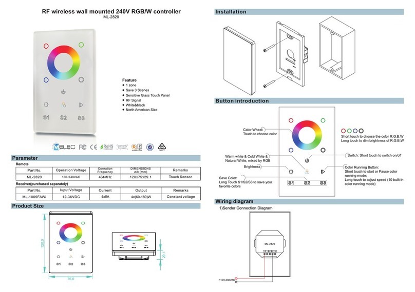
M-Elec ML-2820-US3 User manual

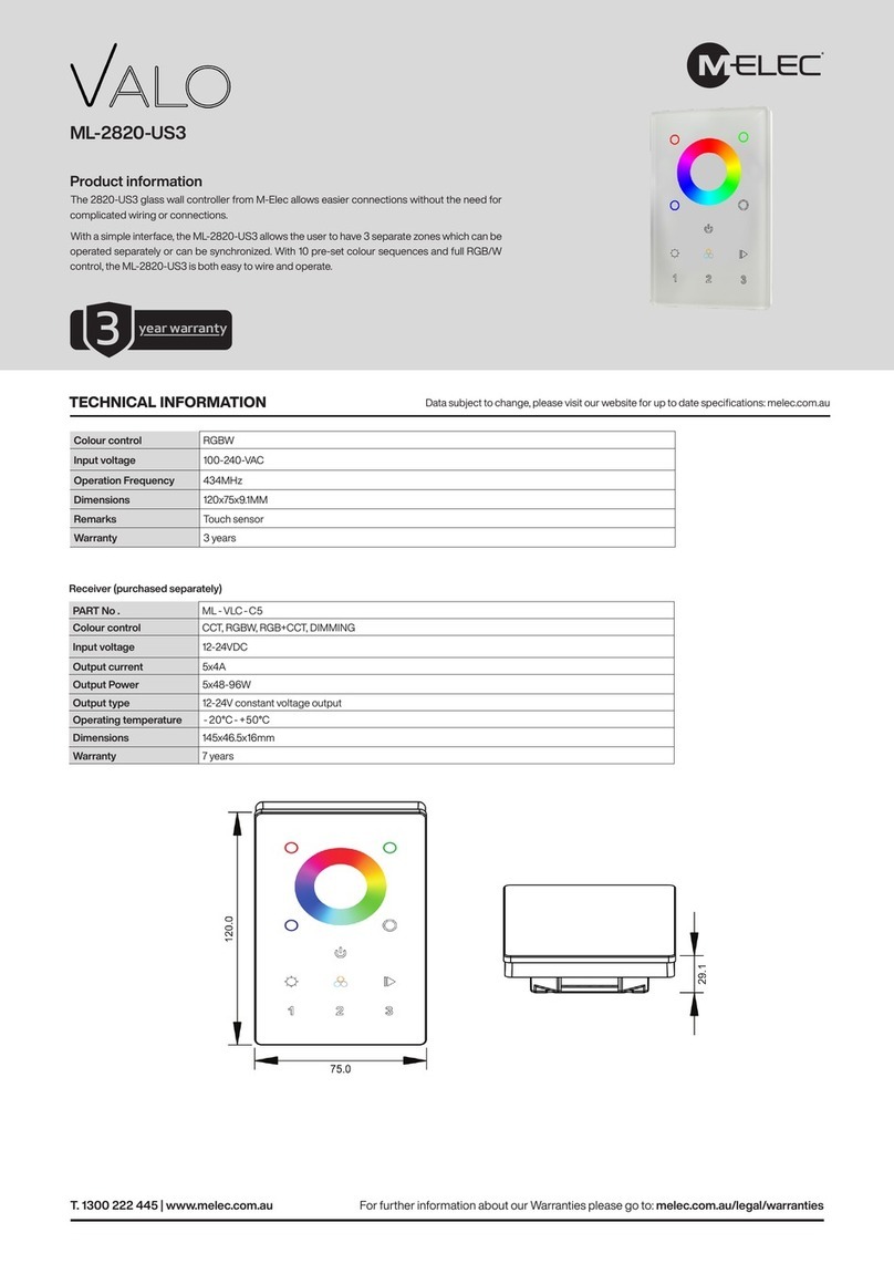
RF wireless wall mounted RGB/W controller
Parameter
ML-2820-US3
Product Size
Installation
Button introduction
Remote
Part No. Operation Voltage DIMENSIONS
ø/h (mm)
Operation
Frequency
ML-2820-US3 100-240VAC 120x75x29.1
434MHz
Remarks
Touch Sensor
Wiring diagram
3 zones
Sensitive Glass Touch Panel
Feature
RF Signal
120.0
75.0
29.1
Color Wheel:
Touch to choose color
Brightness Color Running Button:
Short touch to start or Pause color
running mode;
Long touch to adjust speed (10 built-in
color running modes)
Warm white & Cold White &
Natural White, mixed by RGB
Switch: Short to switch on/offtouch
Zone Number:
Short touch 1. 2 . 3 to choose the zone
Long touch 1. 2 . 3 to switch on/off
Short to choose the color R.G.B.W
Long touch to dim brightness of R.G.B.W
touch
1)Sender DiagramConnection
110V-230VAC N
L
L N
ML-2820-US3
L N
Part No. Iuput Voltage Remarks
Current
ML-1009FAWi 12-36VDC Constant voltage
4x(60-180)W
4x5A
Output
Receiver(purchased separately)
5
Operation
1.Connecting and Learning Operation
A: Connect the LED device to the assigned colour outputs, matching the LED wiring.
B: Connect Input DC Voltage required for LED device 12 – 36VDC.
C: Power on the RF controller by touching ON/OFF button.
D: Single press the learning button on the receiver.
E: Select & Press the zone button on the controller.
F: Touch the colour wheel.
G: The connected LED device will flash to confirm learning operation.
Note 1: To delete all previous learned remotes, press and hold the learning button down for
approximately 5 seconds until the LED device connectedwill flash to confirm all learned
controllers have been removed.
Note 2: Each ML-2820-US3 controller can control unlimited receivers within the Radio Frequency range.
Note 3: Master/ Slave option is set via the jumper pin, closed is Master with an open jumper is set to
Slave, set on the receiver ML-1009FAWI.
Only one Master can be assigned to each zone. After short periods of time approx. 15seconds,
the master will do a synchronization operationto keep the colour or mode operation across the
slaves connected in the zone.
2.Using the Colour wheel
Changing each zones colour is done by first selecting the desired zone then by touching the colour wheel, If
you would like to control all3 zones simultaneously press buttons 1 & 2 &, then touch the colour wheel.
3.Colour changing mode
Select the required zone by pressing 1, 2 or 3 then press the button for start, pressing the again will
stop the colour change to the current colour.
4.Brightness adjustment
Adjusting the brightness can be done by either a fixed colour or under colour changing mode by pressing
2)Receiver Connection Diagram for Single Unit
Power Supply
12-36VDC
LN
110V-230VAC
RGB/W or CDW LED strip
ML-1009FAWi
Mad e in Chin a
PRI:
Uin=1 2-36V DC
Iin=2 0.5A
SEC:
Uout= 4x(12 -36)V DC
Iout= 4x5A
Pout= 4x(60 -180) W
TEM P RANGE :-2 0℃-+5 0℃
12-36 VD C
W
Safety & Warnings
1) The product shall be installed and serviced by a qualified person.
2) IP20. Please avoid the sun and rain. When installed outdoors, please ensure it is mounted in a water proof
enclosure.
3) Always be sure to mount this unit in an area with proper ventilation to avoid overheating.
4) Please check if the output voltage of any LED power supplies used complies with the working voltage of the
product.
5) Never connect any cables while power is on and always assure correct connections to avoid short circuits
before switching on.
6) Please ensure that the cable is secured tightly to the connector.
7) For latest information please visit our website www.melec.com.au.
Warranty Agreement
1) We provide lifelong technical assistance with this product:
5 year warranty. Every product has printed date on, for example: 1125 means year 2011, week 25.The warranty
is for free repair or replacement and covers manufacturing faults only. For faults beyond the 5-year warranty we
reserve the right to charge for time and parts.
2) Warranty is void if:
Any defects are caused by wrong operation.
Any damages are caused by unauthorized removal, maintenance, modifying, incorrect connection and
replacement of components.
Any damages are due to transportation, vibration etc. after purchase.
Any damages are caused by earthquake, fire, lightning, pollution and abnormal voltage.
Any damages are caused by negligence, inappropriate storing at high temperatures and humidity or near
harmful chemicals.
Product has been updated or changed.
3) Repair or replacement as provided under this warranty is the exclusive remedy to the customer.
Other M-Elec Controllers manuals

M-Elec ADB-2F60B User manual

M-Elec

M-Elec ADB-2F60B User manual

M-Elec ML-2819T8 User manual

M-Elec

M-Elec ML-2819T8 User manual

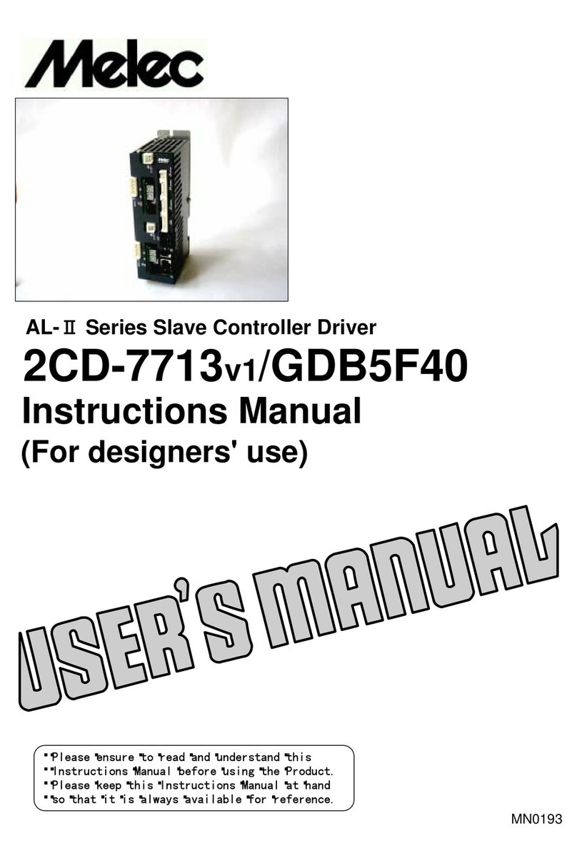
M-Elec AL-II Series User manual

M-Elec

M-Elec AL-II Series User manual

M-Elec Valo ML-2820-US3 User manual

M-Elec

M-Elec Valo ML-2820-US3 User manual

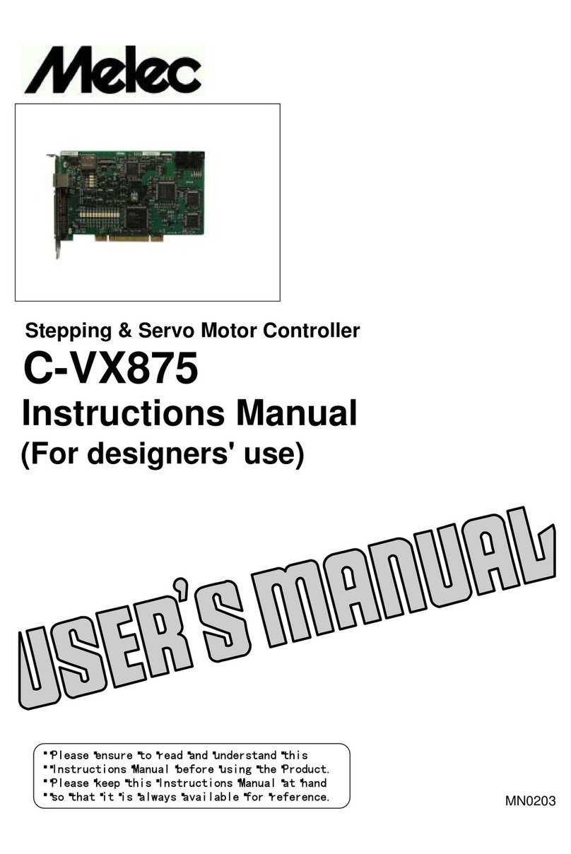
M-Elec C-875 User manual

M-Elec

M-Elec C-875 User manual

M-Elec C-VX875 User manual

M-Elec

M-Elec C-VX875 User manual

M-Elec AL-2 Series User manual

M-Elec

M-Elec AL-2 Series User manual

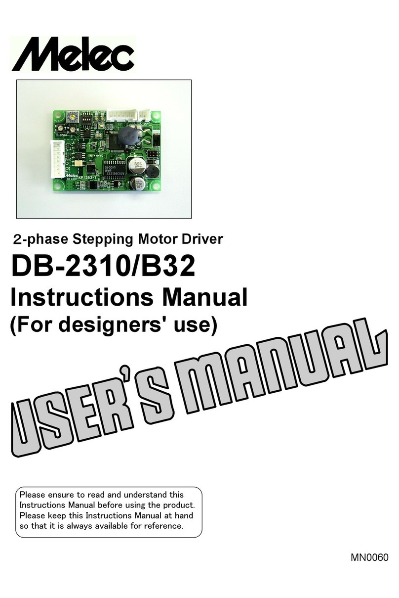
M-Elec DB-2310/B32 User manual

M-Elec

M-Elec DB-2310/B32 User manual

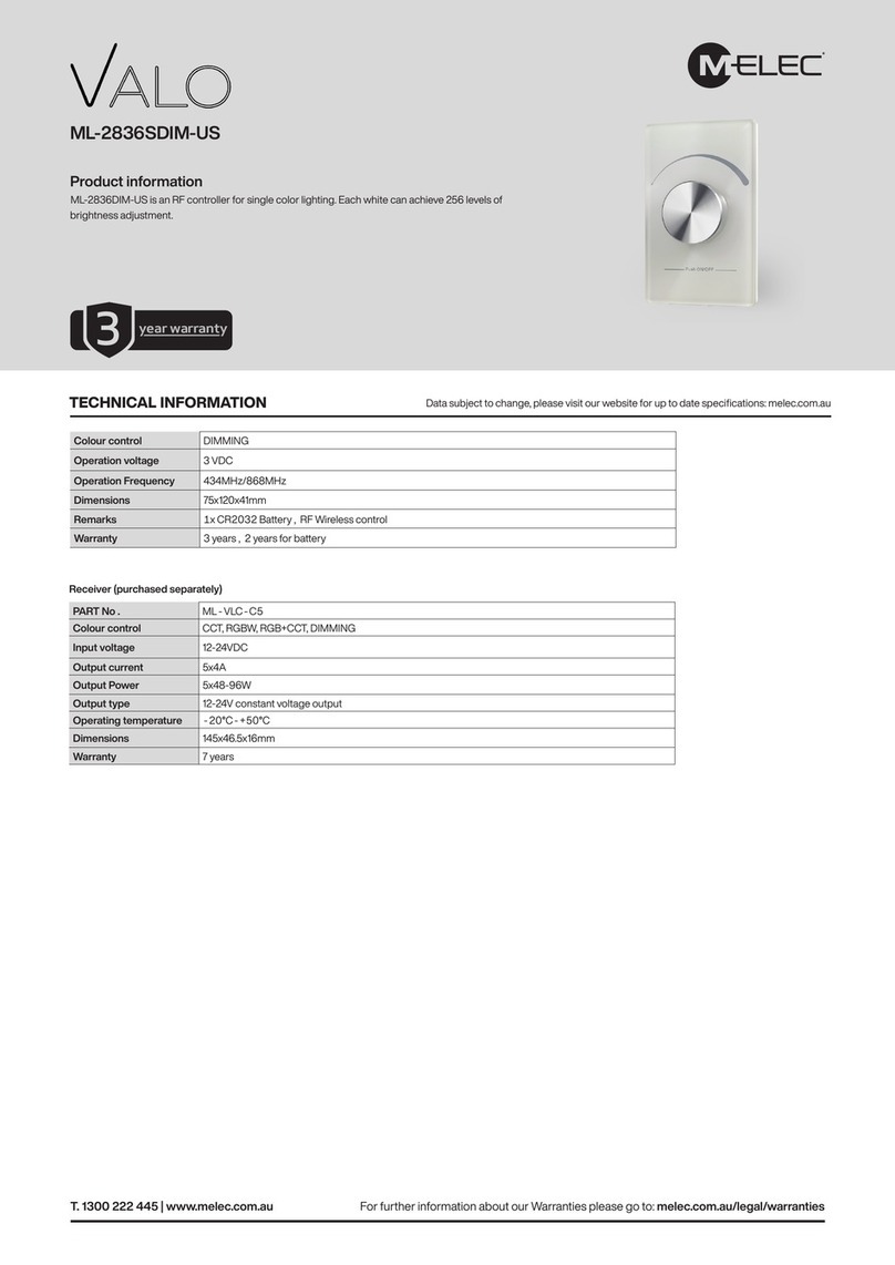
M-Elec VALO ML-2836SDIM-US User manual

M-Elec

M-Elec VALO ML-2836SDIM-US User manual

M-Elec ML-2820 User manual

M-Elec

M-Elec ML-2820 User manual

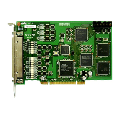
M-Elec C-V870 User manual

M-Elec

M-Elec C-V870 User manual

Popular Controllers manuals by other brands

Soyal AR-721U user guide

Soyal

Soyal AR-721U user guide

Fairford Dfe series installation instructions

Fairford

Fairford Dfe series installation instructions

TECO Tecomat Foxtrot CP-1004 System design guide

TECO

TECO Tecomat Foxtrot CP-1004 System design guide

Thermokon TS1 3Ph Series Technical data

Thermokon

Thermokon TS1 3Ph Series Technical data

Kramer RC-8RKL user manual

Kramer

Kramer RC-8RKL user manual

opto engineering LTDVE2CH-20F instruction manual

opto engineering

opto engineering LTDVE2CH-20F instruction manual

YASKAWA MOTIONPACK-110 DESCRIPTIVE INFORMATION

YASKAWA

YASKAWA MOTIONPACK-110 DESCRIPTIVE INFORMATION

rotork CVL 500 Installation and maintenance instructions

rotork

rotork CVL 500 Installation and maintenance instructions

Shinko ACS-13A Communication instruction manual

Shinko

Shinko ACS-13A Communication instruction manual

Teco Electro Drives TSTA Series Installation and operation manual

Teco Electro Drives

Teco Electro Drives TSTA Series Installation and operation manual

Martin DMX Controller 2518 user manual

Martin

Martin DMX Controller 2518 user manual

VeEX MPA SCM-210 user manual

VeEX

VeEX MPA SCM-210 user manual

Zmotion ZMC412 manual

Zmotion

Zmotion ZMC412 manual

Gotting HG G-73650ZD Basics, Setup and Software

Gotting

Gotting HG G-73650ZD Basics, Setup and Software

Outlaw ICBM-1 owner's manual

Outlaw

Outlaw ICBM-1 owner's manual

Mitsubishi Electric PAC-WHS01HC-E installation manual

Mitsubishi Electric

Mitsubishi Electric PAC-WHS01HC-E installation manual

Emerson Yarway Integral Strainerimpulse 400 Series Instruction, Operation and Maintenance Manual

Emerson

Emerson Yarway Integral Strainerimpulse 400 Series Instruction, Operation and Maintenance Manual

Mitsubishi FX3G Series Programming manual

Mitsubishi

Mitsubishi FX3G Series Programming manual

manuals.online logo
manuals.online logoBrands
  • About & Mission
  • Contact us
  • Privacy Policy
  • Terms and Conditions

Copyright 2025 Manuals.Online. All Rights Reserved.