Endress+Hauser Proline Fieldcheck User manual

BA00067D/06/EN/13.11
71158188
Valid as of version
V 1.07.XX (device software)
Operating Instructions
Proline Fieldcheck
Flow Simulator
E
+
-


Proline Fieldcheck Table of contents
Endress+Hauser 3
Table of contents
1 Safety instructions . . . . . . . . . . . . . . . . 5
1.1 Designated use . . . . . . . . . . . . . . . . . . . . . . . . . . . . 5
1.2 Operational safety . . . . . . . . . . . . . . . . . . . . . . . . . . 5
1.3 Notes on operating Fieldcheck in an environment with
strong electromagnetic interference . . . . . . . . . . . . . 5
1.4 Safety instructions for operating Fieldcheck with Proline
flowmeter systems . . . . . . . . . . . . . . . . . . . . . . . . . . 6
1.5 Notes on safety conventions and icons . . . . . . . . . . . 6
2 Identification . . . . . . . . . . . . . . . . . . . . 7
2.1 Device designation . . . . . . . . . . . . . . . . . . . . . . . . . 7
2.1.1 Fieldcheck nameplate . . . . . . . . . . . . . . . . . 7
2.1.2 Simubox nameplate . . . . . . . . . . . . . . . . . . . 7
2.2 Scope of delivery . . . . . . . . . . . . . . . . . . . . . . . . . . . 8
2.3 CE mark, Declaration of Conformity . . . . . . . . . . . . 8
2.4 Registered trademarks . . . . . . . . . . . . . . . . . . . . . . . 8
3 Wiring . . . . . . . . . . . . . . . . . . . . . . . . . 9
3.1 Overview . . . . . . . . . . . . . . . . . . . . . . . . . . . . . . . . 9
3.1.1 Assignment of Fieldcheck connections . . . . . 9
3.1.2 General procedure . . . . . . . . . . . . . . . . . . . . 9
3.1.3 Supervisor mode . . . . . . . . . . . . . . . . . . . . 10
3.2 Connecting to Promag 10 . . . . . . . . . . . . . . . . . . . 11
3.2.1 Connecting sensor test box to Promag 10 . 12
3.3 Connecting to Promag 50, 53, 55 field housing . . . 13
3.3.1 Connecting sensor test box to
Promag 50, 53, 55 field housing . . . . . . . . 14
3.4 Connecting to
Promag 50, 53, 55 wall-mount housing . . . . . . . . . 15
3.4.1 Connecting sensor test box to
Promag 50, 53, 55 wall-mount housing . . . 16
3.5 Connecting to Promass 40, 80, 83, 84 field housing 17
3.5.1 Connecting sensor test box to
Promass 40, 80, 83, 84 field housing . . . . . 18
3.6 Connecting to
Promass 80, 83, 84 wall-mount housing . . . . . . . . 19
3.6.1 Connecting sensor test box to
Promass 80, 83, 84 wall-mount housing . . 20
3.7 Connecting to t-mass 65 field housing . . . . . . . . . . 21
3.8 Connecting to remote version of
t-mass 65 with wall-mount housing . . . . . . . . . . . . 22
3.9 Connecting to remote version of
t-mass 65 with field housing . . . . . . . . . . . . . . . . . 23
3.10 Connecting to Prowirl 72, 73 . . . . . . . . . . . . . . . . 24
3.11 Connecting to Prosonic Flow 90, 93
wall-mount housing . . . . . . . . . . . . . . . . . . . . . . . 26
3.12 Connecting to Prosonic Flow 91 field housing . . . . 27
3.13 Connecting to Prosonic Flow 92
in single-chamber housing . . . . . . . . . . . . . . . . . . . 28
3.14 Connecting to Prosonic Flow 92
in twin-chamber housing . . . . . . . . . . . . . . . . . . . . 29
3.15 Connecting to Prosonic Flow 93
in the field housing . . . . . . . . . . . . . . . . . . . . . . . . 30
3.16 Post-connection check . . . . . . . . . . . . . . . . . . . . . . 31
4 Operation . . . . . . . . . . . . . . . . . . . . . . 32
4.1 Display and operating elements . . . . . . . . . . . . . . . 32
4.2 Brief operating instructions for the function matrix . 33
4.3 FieldCare operating software . . . . . . . . . . . . . . . . . 34
5 Commissioning . . . . . . . . . . . . . . . . . . 35
5.1 Function check . . . . . . . . . . . . . . . . . . . . . . . . . . . 35
5.2 Battery operation / power supply . . . . . . . . . . . . . . 35
5.2.1 Operation via the
power adapter/car adapter . . . . . . . . . . . . . 35
5.2.2 Operation via storage battery . . . . . . . . . . . 35
5.3 Commissioning . . . . . . . . . . . . . . . . . . . . . . . . . . . 35
6 Maintenance . . . . . . . . . . . . . . . . . . . . 36
7 Accessories . . . . . . . . . . . . . . . . . . . . . 37
7.1 Device-specific accessories . . . . . . . . . . . . . . . . . . . 37
7.2 Measuring principle-specific accessories . . . . . . . . . 37
7.3 Service-specific accessories . . . . . . . . . . . . . . . . . . . 38
7.4 Software history . . . . . . . . . . . . . . . . . . . . . . . . . . . 38
8 Technical data . . . . . . . . . . . . . . . . . . . 39
8.1 Technical data at a glance . . . . . . . . . . . . . . . . . . . 39
8.1.1 Input . . . . . . . . . . . . . . . . . . . . . . . . . . . . . 39
8.1.2 Power supply . . . . . . . . . . . . . . . . . . . . . . . 39
8.1.3 Performance characteristics . . . . . . . . . . . . 39
8.1.4 Operating conditions (Environment) . . . . . . 39
8.1.5 Mechanical construction . . . . . . . . . . . . . . 40
8.1.6 Human interface . . . . . . . . . . . . . . . . . . . . 40
8.1.8 Accessories . . . . . . . . . . . . . . . . . . . . . . . . 40
9 Device functions - general section . . . . 41
9.1 Notes . . . . . . . . . . . . . . . . . . . . . . . . . . . . . . . . . . 41
9.1.1 Using the table of contents to locate a function
description . . . . . . . . . . . . . . . . . . . . . . . . . 41
9.1.2 Using the graphic of the function matrix to
locate a function description . . . . . . . . . . . 42
9.2 Block USER INTERFACE . . . . . . . . . . . . . . . . . . . . 43
9.2.1 Group CONTROL . . . . . . . . . . . . . . . . . . . 43
9.3 Block BASIC INFORMATION . . . . . . . . . . . . . . . . 45
9.3.1 Group DEVICE DATA . . . . . . . . . . . . . . . . 45
9.3.2 Group READ IN PARAMETERS . . . . . . . . . 45
9.4 Block SUPERVISION . . . . . . . . . . . . . . . . . . . . . . . 46
9.4.1 Group RESULTS . . . . . . . . . . . . . . . . . . . . 46
9.4.2 Group VERSION INFO . . . . . . . . . . . . . . . 48
10 Device functions - electromagnetic
measuring systems . . . . . . . . . . . . . . . 49
10.1 Block FUNCTION . . . . . . . . . . . . . . . . . . . . . . . . . 49
10.1.1 Group SIMULATION . . . . . . . . . . . . . . . . . 50
10.1.2 Group VERIFICATION TRANSMITTER . . 53
10.1.3 Group VERIFICATION SENSOR . . . . . . . . 58
Proline Fieldcheck Table of contents
4Endress+Hauser
11 Device functions - Coriolis measuring
systems . . . . . . . . . . . . . . . . . . . . . . . . 61
11.1 Block FUNCTION . . . . . . . . . . . . . . . . . . . . . . . . . 61
11.1.1 Group SIMULATION . . . . . . . . . . . . . . . . . 62
11.1.2 Group VERIFICATION TRANSMITTER . . 65
11.1.3 Group VERIFICATION SENSOR . . . . . . . . 71
12 Device functions - thermal measuring
systems . . . . . . . . . . . . . . . . . . . . . . . . 73
12.1 Block FUNCTION . . . . . . . . . . . . . . . . . . . . . . . . . 73
12.1.1 Group SIMULATION . . . . . . . . . . . . . . . . . 74
12.1.2 Group VERIFICATION TRANSMITTER . . 76
13 Device functions - vortex measuring
devices . . . . . . . . . . . . . . . . . . . . . . . . 81
13.1 Block FUNCTION . . . . . . . . . . . . . . . . . . . . . . . . . 81
13.1.1 Group SIMULATION . . . . . . . . . . . . . . . . . 82
13.1.2 Group VERIFICATION TRANSMITTER . . 85
14 Device functions - ultrasonic measuring
systems . . . . . . . . . . . . . . . . . . . . . . . . 90
14.1 Block FUNCTION . . . . . . . . . . . . . . . . . . . . . . . . . 90
14.1.1 Group SIMULATION . . . . . . . . . . . . . . . . . 91
14.1.2 Group VERIFICATION TRANSMITTER . . 93
Index . . . . . . . . . . . . . . . . . . . . . . . . . . . . . . 98

Proline Fieldcheck Safety instructions
Endress+Hauser 5
1 Safety instructions
1.1 Designated use
The Fieldcheck flow simulation system may only be used for the simulation of sensor signals with a
flowmeter of the Endress+Hauser Proline generation of instruments. The device is designed for use
by service technicians who are familiar with the function and operating method of the equipment,
and the specific requirements of the individual applications. The Fieldcheck is a service device
designed for situations in which the flowmeter is "not in operation" (e.g. during servicing and
maintenance in the workshop or under similar conditions etc.). The manufacturer accepts no
liability for damages resulting from incorrect use.
#Warning!
Fieldcheck may not be used in hazardous areas. Appropriate safety measures must be taken.
1.2 Operational safety
• The manufacturer reserves the right to modify technical data without prior notice. Please contact
your Endress+Hauser service organization for information on modifications or updates of these
Operating Instructions.
• The measuring system complies with the general safety requirements in accordance with
EN 61010, the EMC requirements of IEC/EN 61326 and NAMUR Recommendation NE 21.
1.3 Notes on operating Fieldcheck in an environment with
strong electromagnetic interference
To operate Fieldcheck with a Proline flowmeter in the simulation and verification mode, the
electronics and connection compartments must first be opened. In this mode, the radiated RF noise
will not exceed the industrial limits (IEC/EN 61326).
In a heavily disturbed (EMC) environment, you must expect that the operation of both Fieldcheck
and the flowmeter may be temporarily affected. We recommend that - when using Fieldcheck - you
take care to ensure effective ESD protection for the affected measuring point and the operator.
If necessary, the measuring device can be reset:
• Via onsite operation
• By interrupting the supply voltage
• By restarting Fieldcheck

Safety instructions Proline Fieldcheck
6Endress+Hauser
1.4 Safety instructions for operating Fieldcheck with
Proline flowmeter systems with an approval for
hazardous areas (e.g. II3GD, II2GD, II1/2GD, II1GD,
Zone 1, Zone 21, Zone 2, Zone 22, Ga, Gb, Gc, Da, Db,
Dc, Class I/II/III Div.1 or Div.2)
The following safety instructions must be observed when using Fieldcheck and its related
accessories (Simubox, test box, etc.) with Proline flowmeter systems with approval for use in
hazardous areas:
• With regard to explosion protection, the Fieldcheck and related accessories are unapproved
equipment. The Fieldcheck must be used without an external power supply (charging mode).
Power is only provided by storage batteries.
• The transportation, connection and operation of the Fieldcheck is not permitted in potentially
explosive atmospheres.
• Fieldcheck may only be connected to flowmeters if no part of the measuring system (sensor,
measuring tube interior, transmitter, etc.) is exposed to an explosive atmosphere or if the
Fieldcheck and related accessories are only electrically connected to device parts that are located
in a non-explosive atmosphere. In the case of the remote version, it does not suffice to regard the
transmitter as a separate unit if the transmitter and sensor are connected electrically.
Connecting to Proline flowmeters with intrinsically safe circuits
The output levels of the Fieldcheck and its related accessories are adjusted to the functional values
of the contacting circuits. Any damage to internal protective functions of intrinsically safe circuits is
ruled out. The correct functioning of the Fieldcheck must be validated by regular calibrations.
Calibrating the Fieldcheck
As with other measuring equipment, we recommend calibrating the Fieldcheck on an annual basis.
Measuring the open-circuit voltage and the short-circuit current at every output is an integral part
of the factory calibration.
1.5 Notes on safety conventions and icons
The devices are designed to meet state-of-the-art safety requirements, have been tested, and left the
factory in a condition in which they are safe to operate. The devices comply with the applicable
standards and regulations in accordance with EN 61010 "Protection Measures for Electrical
Equipment for Measurement, Control, Regulation and Laboratory Procedures". They can, however,
be a source of danger if used incorrectly or for anything other than the designated use.
Consequently, always pay particular attention to the safety instructions indicated in these Operating
Instructions by the following icons:
#Warning!
"Warning" indicates an action or procedure which, if not performed correctly, can result in injury
or a safety hazard. Comply strictly with the instructions and proceed with care.
"Caution!
"Caution" indicates an action or procedure which, if not performed correctly, can result in the
incorrect operation or destruction of the device. Comply strictly with the instructions.
!Note!
"Note" indicates an action or procedure which, if not performed correctly, can have an indirect
effect on operation or trigger an unexpected response on the part of the device.

Proline Fieldcheck Identification
Endress+Hauser 7
2 Identification
2.1 Device designation
The Fieldcheck flow simulation system consists of the following components:
• The Fieldcheck flow simulator itself
• The Simubox for correct connection to measuring device in question
2.1.1 Fieldcheck nameplate
a0001711
Fig. 1: Nameplate specifications for the Fieldcheck flow simulator (example)
1 Order code/serial number
2 Permitted ambient temperature range
3 Space reserved for additional information on the device version (approvals, certificates, etc.)
4 Degree of protection
5 Please observe the Operating Instructions
2.1.2 Simubox nameplate
a0001712
Fig. 2: Nameplate specifications for the Simubox (example)
1 Order code/serial number
2 Permitted ambient temperature range
3 Space reserved for additional information on the device version (approvals, certificates, etc.)
4 Degree of protection
5 Please observe the Operating Instructions
Order Code:
Ser.No.: 50095658
12345678901
0°C(+32°F)<Tamb<+60°C(+140°F)
1
2
FIELDCHECK
IP40
i
4
5
3N12895
Order Code:
Ser.No.: 50097102
12345678901
0°C(+32°F)<Tamb<+60°C(+140°F)
SIMUBOX-MID
IP40
i
3N12895
1
2
4
5

Identification Proline Fieldcheck
8Endress+Hauser
2.2 Scope of delivery
The equipment supplied with Fieldcheck comprises the following components:
• The Fieldcheck flow simulator with battery pack
• A connecting cable for the service interface
• A connecting cable for the Simubox
• Two connecting cables for the current and frequency output
• An RS 232 connecting cable for connecting Fieldcheck to a computer (
9-pin COM interface)
• A power adapter
• A softcase
• Operating Instructions
The Simuboxes for the respective flow measuring systems, the sensor test boxes and the system-
specific sensor adapters are available via separate order numbers.
2.3 CE mark, Declaration of Conformity
The devices are designed to meet state-of-the-art safety requirements, comply with good
engineering practices, have been tested, and left the factory in a condition in which they are safe to
operate.
The devices comply with the applicable standards and regulations in accordance with EN 61010-1
"Protection Measures for Electrical Equipment for Measurement, Control, Regulation and
Laboratory Procedures" as well as with the EMC requirements of IEC/EN 61326.
The measuring system described in these Operating Instructions meets the statutory requirements
and complies with the EC Directives which are listed in the Declaration of Conformity.
Endress+Hauser confirms successful testing of the device and compliance with the EC Directives
by affixing the CE mark.
2.4 Registered trademarks
HART®
Registered trademark of the HART Communication Foundation, Austin, USA
PROFIBUS®
Registered trademark of the PROFIBUS User Organization, Karlsruhe, Germany
FOUNDATION™ Fieldbus
Registered trademark of the Fieldbus FOUNDATION, Austin, USA
Fieldcheck®
Registered trademark of Endress+Hauser Flowtec AG, Reinach, Switzerland
FieldCare®
Registered trademark of Endress+Hauser Process Solutions AG, Reinach, Switzerland

Proline Fieldcheck Wiring
Endress+Hauser 9
3 Wiring
#Warning!
When connecting Ex-certified devices, see the notes and diagrams in the Ex-specific supplement to
the Operating Instructions of the relevant measuring device. Fieldcheck may not be used in
hazardous areas. Please do not hesitate to contact your Endress+Hauser service organization if you
have any questions.
3.1 Overview
3.1.1 Assignment of Fieldcheck connections
a0001704
Fig. 3: Fieldcheck connections
1 Connection to the frequency output of the device
2 Connection to the current output of the device
3 Connection to the internal service interface of the device
4 Connection to the Simubox
5 Connection to the plug-in power supply unit
3.1.2 General procedure
For correct synchronization with the measuring device, we recommend that you abide by the
following procedure when connecting Fieldcheck.
1. Start the device to be tested.
2. First connect the cables to the flowmeter (ä11 to ä30).
3. Next, connect the cables on the front panel of Fieldcheck.
!Note!
Fieldcheck does not need an external power supply during operation. Power is provided by internal
storage batteries. Make sure that the storage batteries are fully charged before beginning a
simulation.
12345
DCSIMSRV
I
F

Wiring Proline Fieldcheck
10 Endress+Hauser
3.1.3 Supervisor mode
If Fieldcheck is operated with the external power unit or a current or frequency measuring cable,
and is not connected to a transmitter, the following message appears on the display after a brief
period:
• In this mode, all the result data saved can be called up and also deleted.
• The version data (hardware/software version, serial number, date of last calibration) can also be
called up.
• If the current or frequency measuring cable is used for supervisor mode, the charging status of the
battery can be read from the USER INTERFACE Block. This status cannot, however, be read
when an external power supply is used.
SUPERVISOR MODE
IS ACTIVATED
CONTINUE WITH ENTER

Proline Fieldcheck Wiring
Endress+Hauser 11
3.2 Connecting to Promag 10
!Note!
Fieldcheck can only be used with devices with software version 1.01.xx or higher.
"Caution!
Connect the ground terminals on the cables to the uninsulated housing components or to the
ground terminals in the connection compartment.
1. Remove the cover of the electronics compartment (3).
2. Remove the local display (4) from the connection compartment cover.
3. Press the side latches (5) and fold down the connection compartment cover.
4. Pull the sensor signal cable connector out of the amplifier socket (6).
5. Plug the Simubox cable connector into the amplifier socket (6).
6. Connect Fieldcheck to the current and pulse output (7) of the transmitter.
!Note!
The configuration of the outputs depends on the product type and the order version of the
tested transmitter. To find out which terminal pairs are assigned to the outputs, see the
"Wiring" section of the flowmeter Operating Instructions.
7. Connect Fieldcheck to the service connector (8).
a0001726
Fig. 4: Connecting Fieldcheck to Promag 10
1 Fieldcheck flow simulator
2 Simubox
3 Electronics compartment cover
4 Local display
5 Latches
6 Amplifier socket
7 Terminals for current/pulse output
8 Service plug-in jack
6
8
7
Esc
1
2
4
3
5

Wiring Proline Fieldcheck
12 Endress+Hauser
3.2.1 Connecting sensor test box to Promag 10
!Note!
• Fieldcheck can only be used with devices with software version 1.01.xx or higher.
• The start-up procedure must have been executed via the Simubox before connecting the sensor
test box.
"Caution!
Connect the ground terminal of the adapter to the uninsulated housing components or to the
ground terminals in the connection compartment.
1. Connect the sensor test box to Fieldcheck with the simulation cable.
2. Connect the sensor test box to the sensor cable connector and, if necessary, also to the
magnetic coil connector using the MID adapter.
A0013371
Fig. 5: MID adapter for sensor test box
1 Sensor test box
2 MID adapter
3 Coil current connector
4 Electrode connector
5 Ground terminal
6 Connection to Fieldcheck (with Simubox cable)
1
2
3
4
6
5

Proline Fieldcheck Wiring
Endress+Hauser 13
3.3 Connecting to Promag 50, 53, 55 field housing
"Caution!
Connect the ground terminals on the cables to the uninsulated housing components or to the
ground terminals in the connection compartment.
1. Remove the cover of the electronics compartment (5).
2. Pull down or open the local display (6).
3. Pull the sensor signal cable connector out of the amplifier socket (7).
4. Plug the Simubox cable connector into the amplifier socket (7).
5. Remove the cover of the connection compartment (8) from the transmitter housing.
6. Connect Fieldcheck to the current and frequency outputs of the transmitter
(terminal pairs 22/23, 24/25 or 26/27).
!Note!
The configuration of the outputs depends on the product type and the order version of the
tested transmitter. To find out which terminal pairs are assigned to the outputs, see the
"Wiring" Section of the flowmeter Operating Instructions.
7. Connect Fieldcheck to the service connector (9).
a0001698
Fig. 6: Connecting Fieldcheck to Promag 50, 53, 55 (field housing)
1 Fieldcheck flow simulator
2 Simubox
3 Stainless steel transmitter
4 Aluminum transmitter
5 Electronics compartment cover
6 Local display
7 Amplifier socket
8 Connection compartment cover
9 Service connector
27
25
23
21
2
1
26
24
22
20
L1 (L+)
N (L-)
E
-
+
8
3
5
4
8
5
7
6
2
1
9

Wiring Proline Fieldcheck
14 Endress+Hauser
3.3.1 Connecting sensor test box to Promag 50, 53, 55 field housing
!Note!
The start-up procedure must have been executed via the Simubox before connecting the sensor test
box.
"Caution!
Connect the ground terminal of the adapter to the uninsulated housing components or to the
ground terminals in the connection compartment.
1. Connect the sensor test box to Fieldcheck with the simulation cable.
2. Connect the sensor test box to the sensor cable connector and, if necessary, also to the
magnetic coil connector using the MID adapter.
A0013371
Fig. 7: MID adapter for sensor test box
1 Sensor test box
2 MID adapter
3 Coil current connector
4 Electrode connector
5 Ground terminal
6 Connection to Fieldcheck (with Simubox cable)
1
2
3
4
6
5

Proline Fieldcheck Wiring
Endress+Hauser 15
3.4 Connecting to Promag 50, 53, 55 wall-mount housing
"Caution!
Connect the ground terminals on the cables to the uninsulated housing components or to the
ground terminals in the connection compartment.
1. Remove the cover of the connection compartment (4).
2. Completely remove the terminal block (5, terminal nos. 4 to 8, 36+37) from the base.
"Caution!
If the terminal block is not removed, a correct simulation/verification is not guaranteed.
3. Plug the Simubox cable connector into the amplifier socket (7).
4. Connect Fieldcheck to the current and frequency outputs of the transmitter
(terminal pairs 22/23, 24/25 or 26/27).
!Note!
The configuration of the outputs depends on the product type and the order version of the
tested transmitter. To find out which terminal pairs are assigned to the outputs, see the
"Wiring" section of the flowmeter Operating Instructions.
5. Connect Fieldcheck to the service connector (6).
a0001699
Fig. 8: Connecting Fieldcheck to Promag 50, 53, 55 (wall-mount housing)
1 Fieldcheck flow simulator
2 Simubox
3 Transmitter wall-mount housing
4 Connection compartment cover
5 Terminal block
6 Service connector
7 Amplifier socket
1222 2320 21 24 25 26 27
41
42
657843736
3
4
57
6
2
1

Wiring Proline Fieldcheck
16 Endress+Hauser
3.4.1 Connecting sensor test box to Promag 50, 53, 55 wall-mount
housing
!Note!
The start-up procedure must have been executed via the Simubox before connecting the sensor test
box.
"Caution!
Connect the ground terminal of the adapter to the uninsulated housing components or to the
ground terminals in the connection compartment.
1. Connect the sensor test box to Fieldcheck with the simulation cable.
2. Connect the sensor test box to the sensor cable connector and, if necessary, also to the cable
ends of the coil cable using the MID adapter.
A0013372
Fig. 9: MID adapter for sensor test box
1 Sensor test box
2 MID adapter
3 Electrode connector
4 Coil current cable
5 Ground terminal
6 Connection to Fieldcheck (with Simubox cable)
2
3
4
5
1
6

Proline Fieldcheck Wiring
Endress+Hauser 17
3.5 Connecting to Promass 40, 80, 83, 84 field housing
"Caution!
Connect the ground terminals on the cables to the uninsulated housing components or to the
ground terminals in the connection compartment.
1. Remove the cover of the electronics compartment (5).
2. Remove the local display.
3. Disconnect the excitation current cable from the excitation current socket (6).
#Warning!
The excitation current cable must be disconnected as otherwise the measuring tube could
vibrate in the resonance frequency and become damaged!
4. Pull the sensor signal cable connector out of the amplifier socket (7).
5. Plug the Simubox cable connector into the amplifier socket (7).
The adapter (å11) should be used to connect the Simubox to Promass 40 measuring
devices.
6. Remove the cover of the connection compartment (8) from the transmitter housing.
7. Connect Fieldcheck to the current and frequency outputs of the transmitter
(terminal pairs 22/23, 24/25 or 26/27).
!Note!
The configuration of the outputs depends on the product type and the order version of the
tested transmitter. To find out which terminal pairs are assigned to the outputs, see the
"Wiring" section of the flowmeter Operating Instructions.
8. Connect Fieldcheck to the service connector (9).
a0001700
Fig. 10: Connecting Fieldcheck to Promass 40, 80, 83, 84 (field housing)
1 Fieldcheck flow simulator
2 Simubox
3 Stainless steel transmitter
4 Aluminum transmitter
5 Electronics compartment cover
6 Excitation current socket
7 Amplifier socket
8 Connection compartment cover
9 Service connector
27
25
23
21
2
1
26
24
22
20
L1 (L+)
N (L-)
8
3
5
4
8
5
7
6
2
1
9

Wiring Proline Fieldcheck
18 Endress+Hauser
3.5.1 Connecting sensor test box to Promass 40, 80, 83, 84 field
housing
!Note!
The start-up procedure must have been executed via the Simubox before connecting the sensor test
box.
"Caution!
Connect the ground terminal of the adapter to the uninsulated housing components or to the
ground terminals in the connection compartment.
1. Connect the sensor test box to Fieldcheck with the simulation cable.
2. Connect the sensor test box to the sensor cable connector and the excitation coil connector
with the Coriolis adapter.
A0013401
Fig. 11: Coriolis adapter for sensor test box
1 Sensor test box
2 Coriolis adapter
3 Excitation current connector Promass 40
4 Excitation current connector Promass 80, 83, 84
5 Signal coil connector Promass 40
6 Signal coil connector Promass 80, 83, 84
7 Ground terminal
8 Connection to Fieldcheck (with Simubox cable)
2
4
6
7
5
3
1
8

Proline Fieldcheck Wiring
Endress+Hauser 19
3.6 Connecting to Promass 80, 83, 84 wall-mount housing
"Caution!
Connect the ground terminals on the cables to the uninsulated housing components or to the
ground terminals in the connection compartment.
1. Remove the cover of the connection compartment (4).
2. Remove the excitation current cable (8, terminal pair 41/42).
#Warning!
The excitation current cable must be removed as otherwise the measuring tube could vibrate
in the resonance frequency and become damaged!
3. Completely remove the terminal block (5, terminals 4–12) from the base.
"Caution!
If the terminal block is not removed, a correct simulation/verification is not guaranteed.
4. Plug the Simubox cable connector into the amplifier socket (7).
5. Connect Fieldcheck to the current and frequency outputs of the transmitter
(terminal pairs 22/23, 24/25 or 26/27).
!Note!
The configuration of the outputs depends on the product type and the order version of the
tested transmitter. To find out which terminal pairs are assigned to the outputs, see the
"Wiring" section of the flowmeter Operating Instructions.
6. Connect Fieldcheck to the service connector (6).
a0001701
Fig. 12: Connecting Fieldcheck to Promass 80, 83, 84 (wall-mount housing)
1 Fieldcheck flow simulator
2 Simubox
3 Transmitter wall-mount housing
4 Connection compartment cover
5 Terminals for sensor signal cable
6 Service connector
7 Amplifier socket
8 Terminals for excitation current cable
12
22 23
20 21 24 25 26 27
41 42
6
578
49101112
3
4
5
7
6
2
1
8

Wiring Proline Fieldcheck
20 Endress+Hauser
3.6.1 Connecting sensor test box to Promass 80, 83, 84 wall-mount
housing
!Note!
The start-up procedure must have been executed via the Simubox before connecting the sensor test
box.
"Caution!
Connect the ground terminals of the adapter to the uninsulated housing components or to the
ground terminals in the connection compartment.
1. Connect the sensor test box to Fieldcheck with the simulation cable.
2. Connect the sensor test box to the sensor cable connector and the cable ends of the excitation
coil connector with the Coriolis adapter.
A0013405
Fig. 13: Coriolis adapter for sensor test box
1 Sensor test box
2 Coriolis adapter
3 Sensor cable connector
4 Excitation current cable
5 Ground terminal
6 Connection to Fieldcheck (with Simubox cable)
2
3
4
51
6
Other manuals for Proline Fieldcheck
2
Table of contents
Other Endress+Hauser Test Equipment manuals

Endress+Hauser
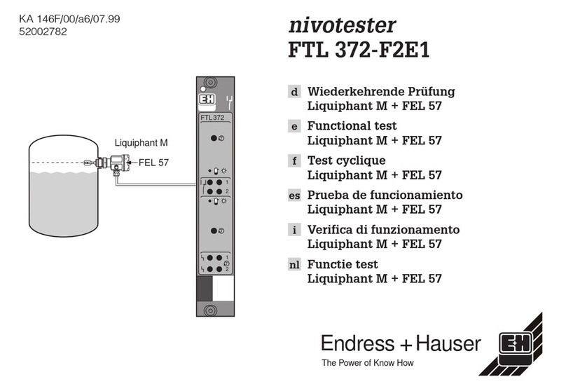
Endress+Hauser nivotester FTL 372-F2E1 User manual

Endress+Hauser
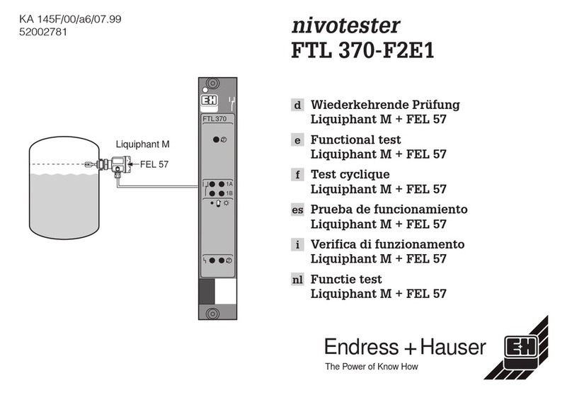
Endress+Hauser Nivotester FTL 370-F2E1 User manual

Endress+Hauser
Endress+Hauser RID 261 User manual

Endress+Hauser
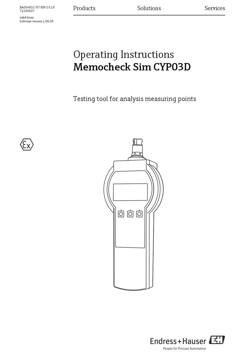
Endress+Hauser Memocheck Sim CYP03D User manual

Endress+Hauser
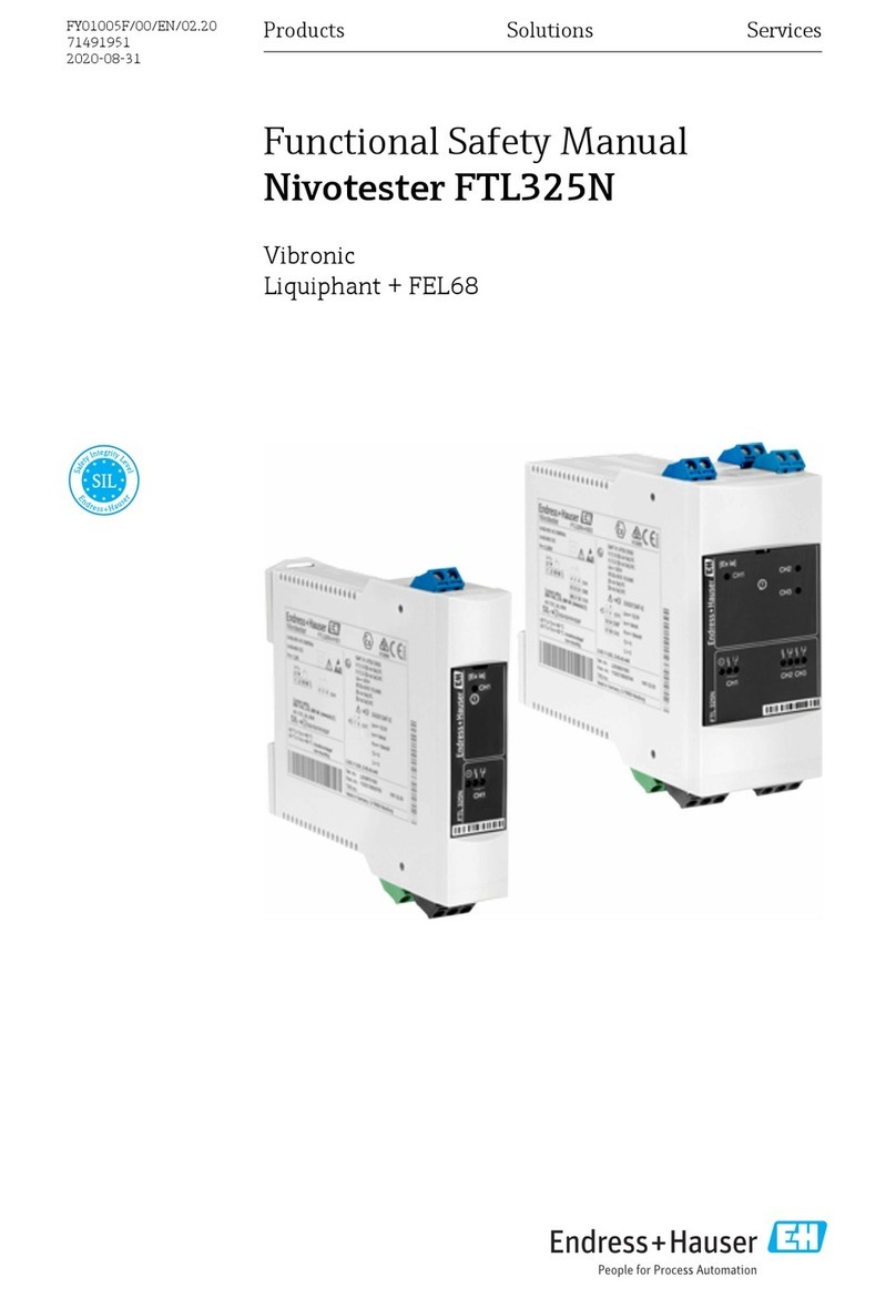
Endress+Hauser Nivotester FTL325N-**** Series Instructions for use

Endress+Hauser
Endress+Hauser Tankvision Multi Scan NXA83B User manual