BASEWEST TS-421 Use and care manual


BASEWEST
Calibration Manual
Model TS-421 Test Set
Page 2 of 12 25-60-46
June 20, 2023
Battery Status Icon
1.0 SCOPE
This manual covers the calibration of the Model TS-421 test set. Calibration is recommended
annually, but user requirements may indicate a different calibration schedule. This manual and
the companion TS-421 Operating Manual No. 25-60-45 are available at the BaseWest website
(www.basewest.com).
2.0 DESCRIPTION
The BaseWest Model TS-421 test set is a rechargeable, handheld instrument with a touch-
screen interface and readout designed specifically for testing airline escape slide lighting
systems, harnesses and batteries. The Model TS-421 provides the following functions:
•Voltmeter with Built-in Resistor Load Bank –The Voltmeter Mode is used to measure and
display the voltage of the internal cell stack of a connected slide light battery, under open or
closed-circuit conditions under user-selectable resistive loads.
•Ammeter with Integral 5VDC Regulated Power Supply –The Ammeter Mode is used to
measure and display the electrical current draw of a connected slide light harness, with input
from internal regulated 5VDC power supply.
3.0 GENERAL ARRANGEMENT
The general arrangement of the Model TS-421 test set is shown in the figures below.
Figure 1. TS-421 General Arrangement
Touchscreen Display
(Home Screen with test
mode selection shown)
Recharge
Receptacle
AC Recharging
Receptacle
Connector Block (Figure 2)
RED Button
(Press-To-Test)
Enclosure with
Integral Battery Pack
and Removable
Protective Cover
BASEWEST
Calibration Manual
Model TS-421 Test Set
Page 3 of 12 25-60-46
June 20, 2023
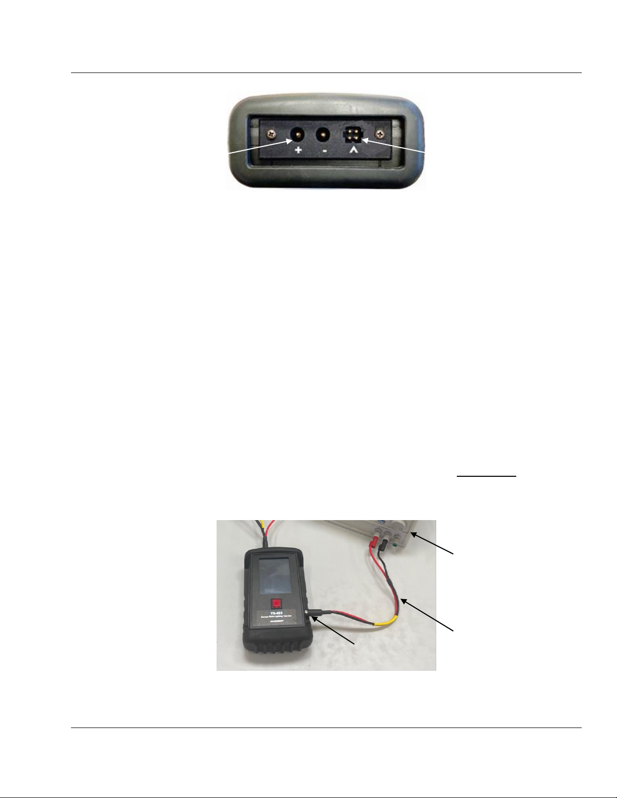
Figure 2. Connector Block
4.0 EQUIPMENT REQUIRED
The following equipment is recommended for TS-421 calibration:
•Regulated DC Power Supplies No 1 and No. 2 (+/- 0.5%, 0 ~ 9 VDC, 0 ~ 3A)
•Digital Voltmeter, 4½ digits, 0.05% or better
•Digital Ammeter, 4½ digits, 0.05% or better, capable of handling 3 amps
•Power Cable, BaseWest P/N 7-6930
•Test Cable, BaseWest P/N 7-6931 (with 2Ω, 5%, 25W and 50Ω, 5%, 5W load resistors)
•Banana plug to Banana plug jumper cable, Red
•Banana plug to Banana plug jumper cable, Black
5.0 CALIBRATION MODE SET UP
5.1 Remove all external connections to the test set.
5.2 Adjust an external DC Power Supply to 7.00 VDC, 3 A.
5.3 Connect the P/N 7-6930 Power Cable to Power Supply No. 1
5.4 Press the RED Button to turn the test set ON to the HOME screen and immediately connect the
other end of the P/N 7-6930 Power Cable to the Recharge Receptacle on the test set (Figure 3).
(Note: Pressing the RED while the Home Screen is ON turns the test set OFF.)
Figure 3. P/N 7-6930 Power Cable Connection
4-Contact Connector
for battery testing or
slide light system
testing through battery
Polarized Connections for
testing individual
slide lighting harnesses
Power Cable
P/N 7-6930
Power Supply
No. 1
Recharge
Receptacle
BASEWEST
Calibration Manual
Model TS-421 Test Set
Page 4 of 12 25-60-46
June 20, 2023
5.5 After approximately 2 seconds, the test set should enter Calibration Mode.
a) If entering Calibration Mode takes more than 4 seconds, unplug the Power Cable from the
Recharge Receptacle, turn the test set OFF and ON, and then quickly plug the Power Cable
back in.
b) If the test set does not enter Calibration Mode, and a battery charging symbol ( ) shows
next to battery status icon in the top right hand of the Touchscreen, lower the voltage on the
Power Supply to 6.50VDC and try again.
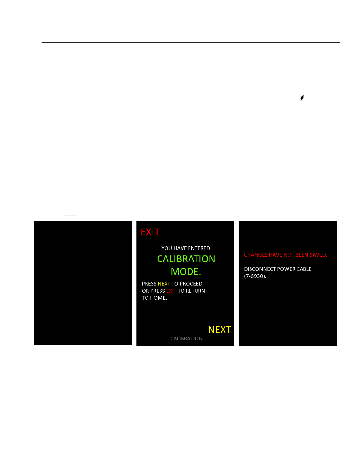
5.6 When entering Calibration Mode, the Touchscreen shows battery pack information (Figure 4).
Record battery pack information on the Calibration Sheet (Appendix A). Press the Touchscreen
anywhere to continue. (Note: The rechargeable battery pack is On Condition with a nominal life
of 5 to 7 years from manufacture date. The battery’s ability to retain charge will diminish over
time and it should be replaced when charge retention becomes unacceptable. Changing the
battery does not affect calibration and can be accomplished at any time.
5.7 To exit Calibration Mode prior to completion of calibration, select EXIT at any time (Figure 5).
Any values up to that time will not be saved (Figure 6). Reenter Calibration Mode and select
NEXT to continue with calibration.
Note: Fonts on the Touchscreen may appear slightly different in figures throughout.
Figure 4. Figure 5. Figure 6.
Battery Info Calibration Mode Intro Calibration Exit
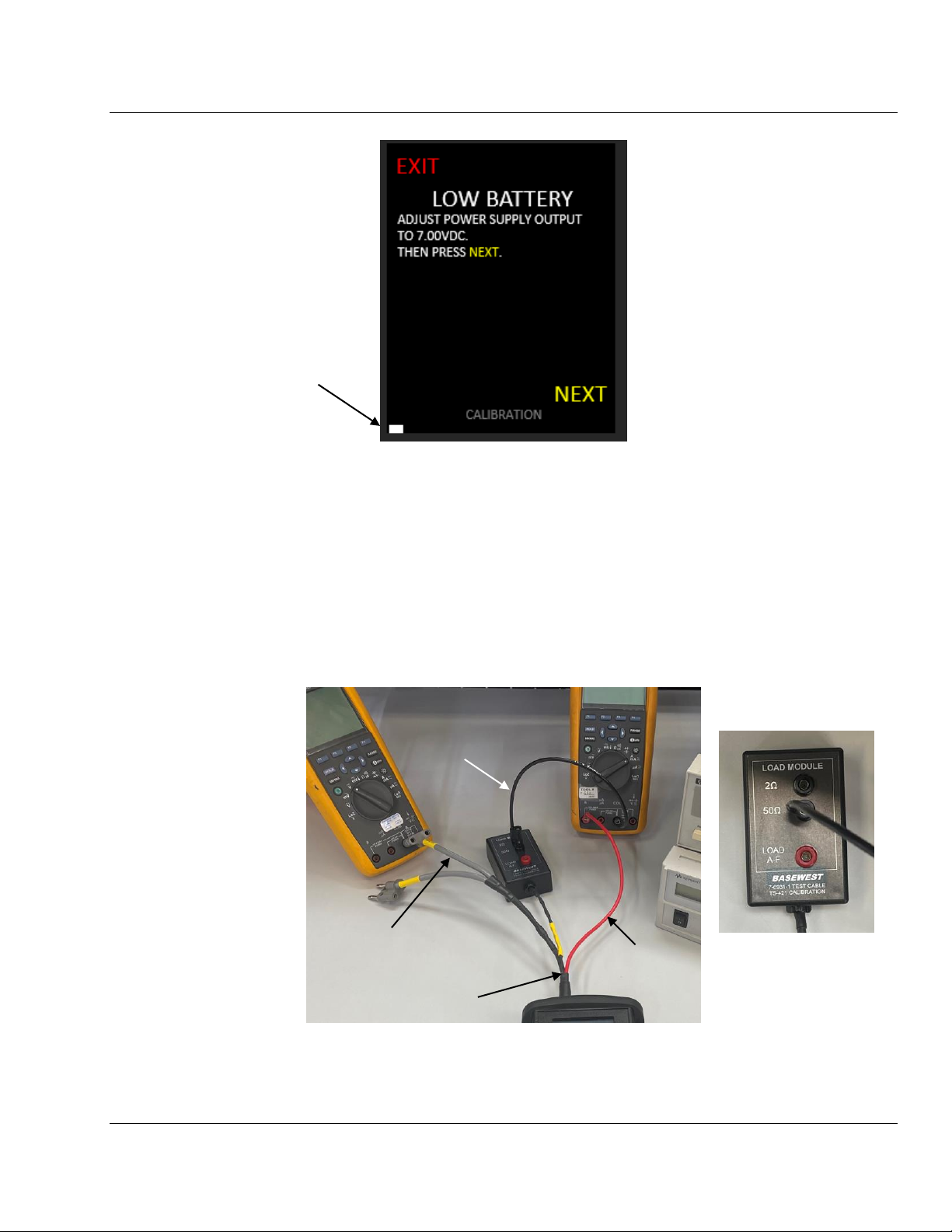
5.8 Per Figure 7, below, adjust the Power Supply to 7.00 0.01 VDC, using a voltmeter if
necessary. Select NEXT to continue. The white bar at the lower left of the screen is a
calibration status indicator which becomes longer as the calibration proceeds.
BATTERY INFO
BW PART NO: 6-1036
BW LOT NO: 1234/56789
MFG DATE: MMM/YY
SUGG REPL DATE: MMM/YY
TS-421 INFO
CAL DATE: MM/DD/YY
FW DATE: MM/DD/YY
TOUCH SCREEN TO PROCEED.
BASEWEST
Calibration Manual
Model TS-421 Test Set
Page 5 of 12 25-60-46
June 20, 2023
Figure 7. Set Low Battery Level
5.9 The internal battery is now disconnected, and the test set is powered by Power Supply No.1 for
the remainder of the calibration sequence. DO NOT adjust voltage until calibration is complete.
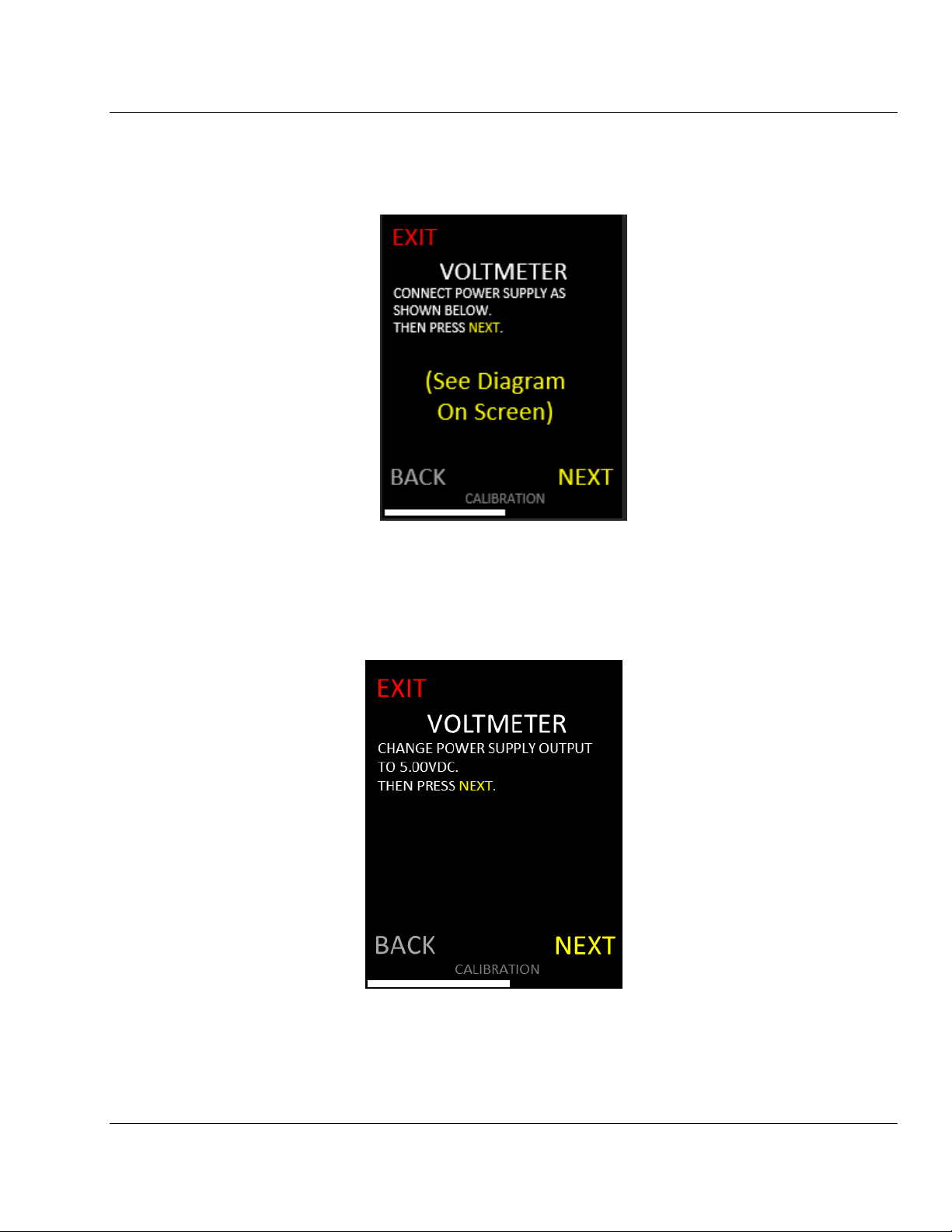
6.0 5VDC OUTPUT SET UP
6.1 Connect the Test Cable P/N 7-6931 as follows: (a) 4-contact plug to the Connector Block (See
Figure 2), (b) the AMMETER test lead to the Voltmeter, (c) the RED test lead to the Ammeter,
and (d) a Black Jumper Lead from the 50receptacle on the Load Module to the Ammeter
(Figures 8A and 8B).
Figure 8A. 5 VDC Output Set Up
Test Cable
P/N 7-6931
AMMETER
Test Lead
Black Jumper to
50Contact on
Load Module
Calibration Status
Indicator Bar
Voltmeter to
the Left
Ammeter to
the Right
Figure 8B.
Load Module
Contact Points
RED
Test Lead

BASEWEST
Calibration Manual
Model TS-421 Test Set
Page 6 of 12 25-60-46
June 20, 2023
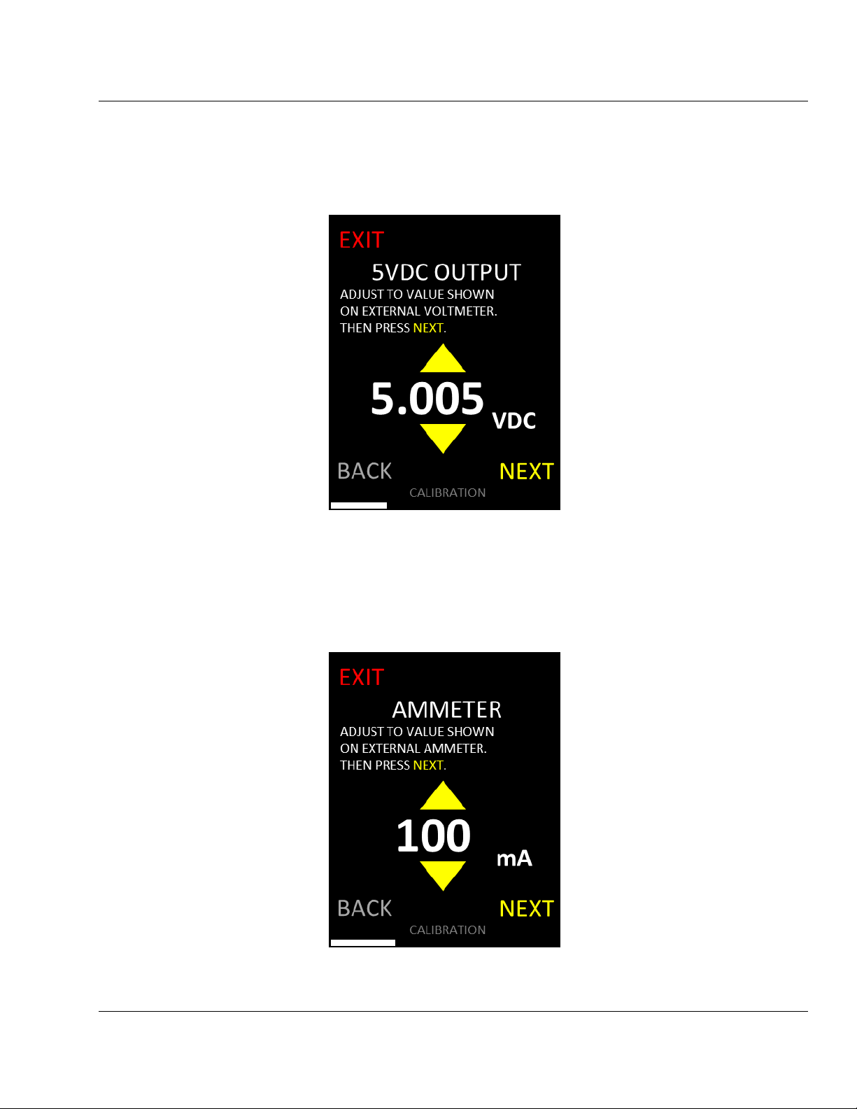
6.2 Select NEXT to continue (Figure 9).
Figure 9. 5VDC Output Setup
6.3 Use arrows on the Touchscreen to change the 5 VDC output so the digital voltmeter reads in a
tight range between 5.003 and 5.007 VDC (Figure 10). Select NEXT to continue.
Figure 10. 5VDC Output Adjustment
BASEWEST
Calibration Manual
Model TS-421 Test Set
Page 7 of 12 25-60-46
June 20, 2023
6.4 Use arrows on the Touchscreen to match the value shown on the Touchscreen with the reading
on the digital voltmeter (Figure 11). Due to possible losses in the cable, the reading can be
loosened up to be between 5.002 and 5.008 VDC. Select NEXT to continue.
Figure 11. 5VDC Output
7.0 AMMETER CALIBRATION
7.1 Use arrows on the Touchscreen to match the value shown on the Touchscreen with the reading
on the digital ammeter (Figure 12). Select NEXT to continue.
Figure 12. 50Current

BASEWEST
Calibration Manual
Model TS-421 Test Set
Page 8 of 12 25-60-46
June 20, 2023
7.2 Move the Black Jumper Lead on the Load Module from the 2contact (Figure 13). Select
NEXT to continue (Figure 14).
Figure 13. Ammeter (2) Load Module Figure 14. Ammeter (2) Setup
7.3 Use arrows on the Touchscreen to match the value shown on the Touchscreen with the reading
on the digital ammeter (Figure 15). Select NEXT to continue. It is recommended to wait for the
ammeter value to drop down to the value on the Touchscreen and hit NEXT at the moment they
are the same.
Figure 15. Current at 2Load
Black Jumper
from Ammeter to
2Contact on
Load Module
*See Figure 8B for
2Contact on
Load Module

BASEWEST
Calibration Manual
Model TS-421 Test Set
Page 9 of 12 25-60-46
June 20, 2023
8.0 VOLTMETER CALIBRATION
8.1 Adjust Power Supply No. 2 to 9.00VDC, 1A.
8.2 Reconnect the Test Cable P/N 7-6931 leads as follows: (a) Swap out the AMMETER Test Lead
plugged into the digital voltmeter with the VOLTMETER Test Lead, (b) connect the RED lead of
Test Cable P/N 7-6931 to Power Supply No. 2 (+) and (c) a Red Jumper Lead from the RED
contact on the Load Module labeled “Load A-F”to the Ammeter. Reconnect the Black Jumper
Lead between Power Supply No. 2 (-) and the Ammeter. (Figure 16)
Figure 16A. Voltmeter Calibration Set Up
Figure 16B. Load Module Contact - Load A-F
VOLTMETER
Test Lead
Red Jumper between
Load A-F Contact
and Ammeter*
RED Lead of 7-6931 to
Power Supply No. 2 (+)
Black Jumper
from Ammeter to
Power Supply No. 2 (-)
Power Supply
No. 2
Power Supply
No. 1
BASEWEST
Calibration Manual
Model TS-421 Test Set
Page 10 of 12 25-60-46
June 20, 2023
8.3 Adjust Power Supply No. 2 until the digital voltmeter reads 9.000 0.005 VDC. Select NEXT to
continue (Figure 17).
Figure 17. Voltmeter (9V) Setup
8.4 Adjust the second Power Supply until the digital voltmeter reads 5.000 0.005 VDC. Select
NEXT (Figure 18) to continue to the Voltage Load Check.
Figure 18. Voltmeter (5V) Setup

BASEWEST
Calibration Manual
Model TS-421 Test Set
Page 11 of 12 25-60-46
June 20, 2023
9.0 VOLTMETER LOAD CHECK
9.1 The “Load A”screen, below, appears. Use arrows on the Touchscreen to match the value
shown on the Touchscreen with the reading on the digital ammeter (Figure 19). Select NEXT to
continue to the “Load B”screen.
Figure 19. Voltmeter Load A
9.2 Repeat this step for all remaining loads B through F.
10.0 CALIBRATION COMPLETION
10.1 The Touchscreen will show the old and new calibration settings (Figure 20). Any readings that
are RED were out of calibration but have been corrected. If any of the loads are RED instead of
GREEN, it is recommended that the test set be returned to BaseWest for rework.
Figure 20. Calibration Summary
BASEWEST
Calibration Manual
Model TS-421 Test Set
Page 12 of 12 25-60-46
June 20, 2023
10.2 Record test information on the attached Calibration Sheet (Appendix A) or in-house form.
10.3 Select ACCEPT to accept changes. If EXIT is selected the test set returns to pre-calibration
status and no changes are made.
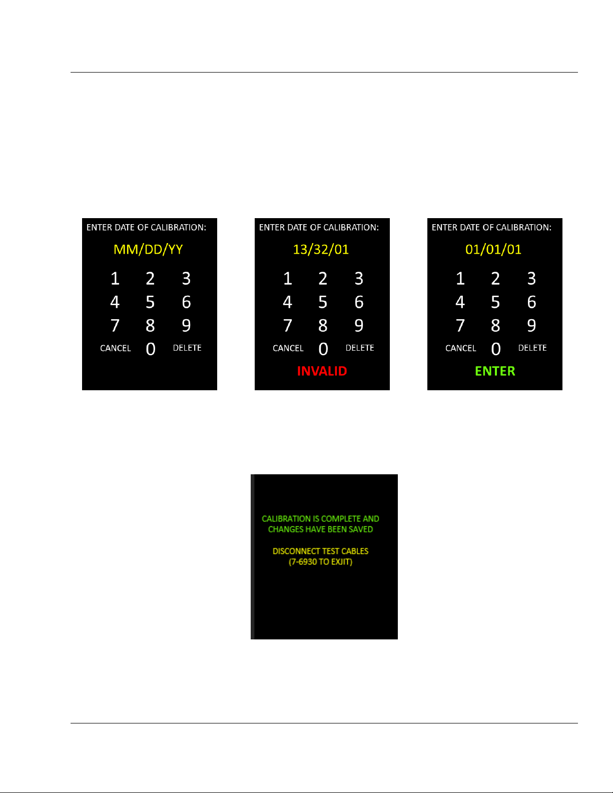
10.4 Enter the date that the calibration took place on (Figure 21). If an invalid date is input, the
screen on Figure 22 will appear and you will not be allowed to continue until a valid date is
entered. When a valid date has been entered, select ENTER to continue.
Figure 21. Date Prompt Figure 22. Invalid DateFigure 23. Valid Date
10.5 Changes are now saved, and calibration is complete (Figure 24). Disconnect the test cables and
jumpers. Return to the HOME screen for testing or turn the test set OFF.
Figure 24. Calibration Complete
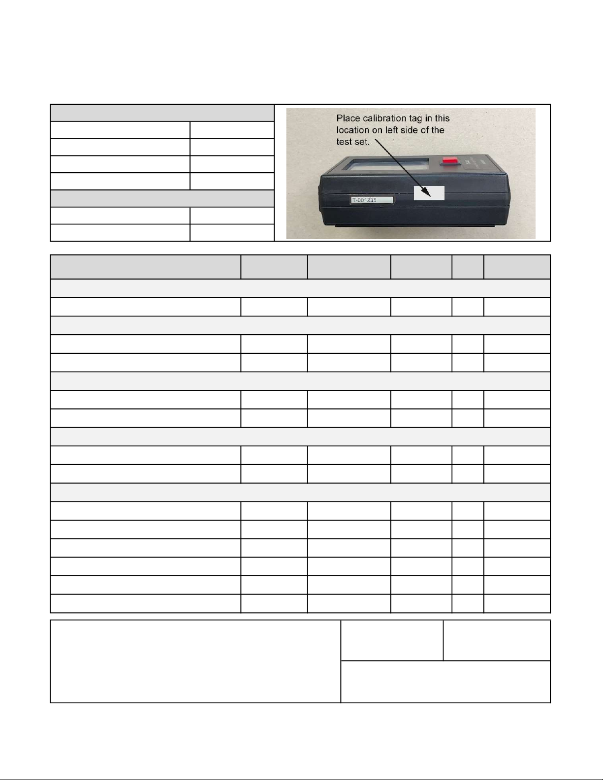
TS-421 Calibration Record 25-60-46
Appendix A
Out of
Tol?
Comments/Repairs/Notes: Calibration Date Calibration Due
Technician
6-1036
T-00
TS-421 Info
Date of Last Calibration
Suggested Replacement Date
Serial Number
Manufacture Date
BaseWest Lot Number
BaseWest Part Number
Section 9.0 - Voltmeter Load Check
Battery Info
Perform Calibration per latest revision of
TS-421 Calibration Manual No. 25-60-46
Load Selector Test @ Load B 69.80 Ω 69.10 to 70.50 Ω -
22.37 to 22.83 Ω -
Ammeter Cal @ 2Ω Load (~2500 mA) *See Note Above +/- 10 mA
-
Load Selector Test @ Load D 90.90 Ω 89.99 to 91.81 Ω -
Load Selector Test @ Load E 34.80 Ω 34.45 to 35.15 Ω -
Load Selector Test @ Load F 49.90 Ω 49.40 to 50.40 Ω
Section 7.0 - Ammeter Calibration (*Note: Readings change with time on test; see Calibration Manual Section 7.0)
Load Selector Test @ Load C 80.60 Ω 79.79 to 81.41 Ω -
Load Selector Test @ Load A 22.60 Ω
Voltmeter Cal @ 5.00VDC 5-00 VDC +/- 10mV
+/- 2 mA
*See Note Above
Section 8.0 - Voltmeter Calibration
+/- 10mVVoltmeter Cal @ 9.00VDC 9.00 VDC
Ammeter Cal @ 50Ω Load (~100 mA)
As Found
After
Calibration
+/- 20mV
Calibration Step
Standard
(Nominal)
Calibration
Tolerance
Section 5.0 - Calibration Mode Set Up
Low Battery Check 7.00 VDC
Internal 5V Cal - Maximum 5.010 VDC +/- 1 mV
Internal 5V Cal - Minimum 5.000 VDC +/- 1 mV
Section 6.0 - 5VDC Output Set Up
Form Date
6/20/23
BQF-332
Other manuals for TS-421
4
Table of contents
Other BASEWEST Test Equipment manuals


