TiePie TP112 Operating and maintenance manual

Programmer's Manual
TiePie DLLs
for: TP112 TiePieSCOPE HS508
TP208 TiePieSCOPE HS801 AWG
TP508 Handyprobe HP2
TP801 AWG ISA Handyscope HS2
TP801 AWG PCI Handyscope HS3
TE6100 Handyscope HS4 (DIFF)
Revision 1.26


Table of contents 3
Table of contents
Table of contents ............................................. 3
Introduction ................................................. 7
How can I... ................................................. 9
Understand the codes .................................... 9
Error codes ...................................... 9
Defined constants ................................. 9
Open / Close the instrument .............................. 11
Search and Initialize the Instrument ................... 11
Close the Instrument .............................. 11
Get information about my instrument ....................... 12
Get the calibration date ............................ 12
Get the instrument serial number ..................... 12
Determine the available input sensitivities ............... 13
Determine the available input resolutions ............... 13
Get the number of input channels .................... 14
Get the maximum sampling frequency ................. 14
Get the maximum record length ..................... 14
Check for availability of DC hardware offset adjustment .... 15
Check for a square wave generator ................... 15
Check for a function generator ....................... 15
Get the maximum amplitude of the function generator ..... 16
Perform a measurement ................................. 17
Start a measurement .............................. 17
Check if the hardware is measuring ................... 17
Abort a running measurement ....................... 17
Read the trigger status ............................. 18
Read the measurement status ....................... 18
Force a trigger ................................... 18
Retrieve the data ....................................... 19
Get the data from a specific channel in binary format ....... 19
Get the date from a specific channel in Volts ............. 19
Get all digital input values ........................... 20
Get one sample of the digital input values ............... 20
Example of use of the routines ....................... 21
Setup for streaming measurements ......................... 23
Using DataReady callback function .................... 23
Using DataReady event ............................ 23
Setting up streaming measurements ................... 24

4Table of contents
Getting the current transfer mode .................... 24
Performing streaming measurements .................. 25
Control the input resolution .............................. 26
Set the input resolution ............................ 26
Get the current input resolution ...................... 26
Control the instrument configuration ........................ 27
Set the instrument configuration ...................... 27
Get the current instrument configuration ............... 27
Control which channels are measured ....................... 28
Get the current measure mode ...................... 28
Set the measure mode ............................ 28
Control the time base .................................. 29
Get the current record length ....................... 29
Set the record length .............................. 29
Get the current number of post samples ............... 30
Set the number of post samples ...................... 30
Get the current sampling frequency ................... 31
Set the sampling frequency .......................... 31
Get the sample clock status ......................... 32
Set the sample clock status .......................... 32
Control the analog input channels .......................... 33
Get the current input sensitivity ...................... 33
Set the input sensitivity ............................. 33
Get the current auto ranging status .................... 34
Set the auto ranging status .......................... 34
Get the current input coupling ....................... 35
Set the input coupling ............................. 35
Get the current DC level value ...................... 36
Set the DC level value ............................. 36
Control the trigger system ................................ 37
Get the current trigger source ....................... 37
Set the trigger source .............................. 37
Get the current trigger mode ........................ 38
Set the trigger mode .............................. 38
Get the current trigger mode for a specific channel ........ 39
Set the trigger mode for a specific channel .............. 39
Get the current trigger level ......................... 40
Set the trigger level ............................... 40
Get the current trigger hysteresis ..................... 41
Set the trigger hysteresis ........................... 41
Select the PXI external trigger signals .................. 42
Get the current used PXI external trigger signals .......... 42
Set the PXI external trigger slopes .................... 43
Get the current PXI external trigger slopes .............. 43

Table of contents 5
Control the digital outputs ................................ 44
Set the digital outputs .............................. 44
Get the current status of the digital outputs .............. 44
Control the Square Wave generator ........................ 45
Get the current square wave generator frequency ........ 45
Set the square wave generator frequency ............... 45
Control the Arbitrary Waveform Generator .................. 46
Set the generator mode ............................ 46
Get the current generator mode ..................... 46
Set the generator signal type ........................ 47
Get the current generator signal type .................. 47
Set the generator amplitude ......................... 48
Get the current generator amplitude .................. 48
Set the generator DC Offset ........................ 49
Get the current generator DC Offset .................. 49
Set the generator signal symmetry .................... 50
Get the current generator signal symmetry .............. 50
Set the generator frequency ......................... 51
Get the current generator frequency .................. 51
Set the generator trigger source ...................... 52
Get the current generator trigger source ............... 52
Fill the function generator waveform memory ........... 53
Set the generator output state ....................... 54
Get the current generator output state ................. 54
Set the generator enabled state ...................... 55
Get the current generator output state ................. 55
Generate bursts .................................. 56
Use the I2Cbus ....................................... 57
Get the I2Cbus speed ............................. 57
Set the I2Cbus speed .............................. 57
Write data to the I2Cbus ........................... 58
Read data from the I2Cbus ......................... 59
Perform resistance measurements .......................... 60
Setup resistance measurements ...................... 60
Retrieve the resistance values ........................ 60
Deprecated routines ......................................... 61
Get the maximum sampling frequency ................. 61
Start a measurement .............................. 61
Get all measurement data in Volts .................... 61
Get one sample of the measurement data, in Volts ........ 62
Get all measurement data, binary ..................... 62
Get one sample of the measurement data, binary ......... 62
Retrieve the measured data in binary format ............. 62

6Table of contents
Retrieve the measured data in Volts ................... 63
Get the current sampling frequency ................... 63
Set the sampling frequency .......................... 63
Get the current trigger timeout value .................. 63
Set the trigger timeout value ........................ 64

Introduction 7
Introduction
This manual describes the available functions in the DLLs for the various TiePie
engineering measuring instruments.
For each instrument, a specific DLL is available. All DLLs have the same routines
and the same programming interface.
Since all instruments have different specifications, a number of functions are
available to determine the specifications of the instrument, like e.g. maximum
sampling frequency, maximum record length, number of channels etc.
Not all instruments have the same functionality as other instruments, like e.g. the
availability of a function generator or digital inputs and outputs. When a certain
function is called and the instrument does not support that functionality, the
routine will return an error code indicating that the functionality is not suppor-
ted.
Since the initial development of the DLLs, many routines have been added to
the DLL, to improve the performance of performing measurements using the
DLL. Several of those routines are replacing older routines, but are not entirely
compatible. To avoid that existing software would no longer function, the old
routines are still available in the DLL, but are marked in the manual as being
obsolete. It is advised to stop using these routines and use the new routines
instead.

8 Introduction

How can I... 9
How can I...
Understand the codes
Error codes
Most routines in the DLL return a status value, that indicates whether the routi-
ne was executed successfully or not. In case of a non successfull execution, the
returb value will indicate the possible cause of the error. The following codes
are used:
Code Names Code Values
Hexadecimal Binary
E_NO_ERRORS = 0x0000;/*0000000000000000*/
E_NO_HARDWARE = 0x0001;/*0000000000000001*/
E_NOT_INITIALIZED = 0x0002;/*0000000000000010*/
E_NOT_SUPPORTED = 0x0004;/*0000000000000100*/
E_NO_GENERATOR = 0x0008;/*0000000000001000*/
E_INVALID_CHANNEL = 0x0010;/*0000000000010000*/
E_INVALID_VALUE = 0x0020;/*0000000000100000*/
E_I2C_ERROR = 0x0040;/*0000000001000000*/
E_I2C_INVALID_ADDRESS = 0x0080;/*0000000010000000*/
E_I2C_INVALID_SIZE = 0x0100;/*0000000100000000*/
E_I2C_NO_ACKNOWLEDGE = 0x0200;/*0000001000000000*/
Defined constants
For several programming environments declaration files (header files) are availa-
ble. These files contain declarations for all the available functions in the DLL, but
also declarations of many used constants, like for trigger sources.
It is recommended that the constants from these declaration files are used in the
application that uses the DLL. When in a future release of the DLL some values
have changed, they will be adapted in the declaration file as well, so the applicati-
on only needs to be recompiled, it will not affect the rest of the program.
All channel related routines use a channel parameter to indicate for which chan-
nel the value is meant:

10 How can I...
lCh1 = 1
lCh2 = 2
lCh3 = 3
lCh4 = 4
The routines that deal with the MeasureMode use different values:
mmCh1 = 1
mmCh2 = 2
mmCh3 = 4
mmCh4 = 8

How can I... 11
Open / Close the instrument
Search and Initialize the Instrument
word InitInstrument( word wAddress )
Descriptions: Initialize the hardware of the instrument. Set default measure-
ment settings, allocate memory and obtain the calibration con-
stants etc.
Parallel port connected instruments, USB instruments and PCI
bus instruments detect the hardware by themselves and ignore
the address parameters.
Input: wAddress The hardware address of the instrument should
be passed to this routine.
Output:Return value E_NO_ERRORS
E_NO_HARDWARE
Note All instruments have their calibration constants in internal, non-volatile
memory, except for the TP208 and TP508. These have to be calibrated
using internal routines. This is done automatically at first startup everyday.
Some relays will begin to click.
Close the Instrument
word ExitInstrument( void )
Description: Close the instrument. Free any allocated resources and memory,
place the relays in their passive state, etc.
Only call this routine when the instrument is no longer required
Input: -
Output: Return value E_NO_ERRORS
E_NOT_INITIALIZED
Note Calling ExitInstrument in LabView causes LabView no longer to be able
to connect to the instrument. LabView has to be closed and opened
again to restore the contact. Therefore, only use ExitInstrument when
the instrument is no longer required, right before closing LabView.

12 How can I...
Get information about my instrument
Get the calibration date
word GetCalibrationDate( dword *dwDate )
Description: This routine returns the calibration date of the instrument. The
date is encoded in a packed 32 bit variable:
31 30 29 28 27 26 25 24 23 22 21 20 19 18 17 16 15 14 13 12 11 10 9 8 7 6 5 4 3 2 1 0
|<-------------------->|<--------------------->|<---------------------------------->|
|day (8 bits) | (month (8 bits) | year (16 bits) |
Example decoding routine in C/C++:
day = number >> 24;/* highest 8 bits */
month = (number >> 16)& 0xFF;/* middle 8 bits */
year = number & 0xFFFF;/* lowest 16 bits */
Input: -
Output: dwDate The calibration date
Return value E_NO_ERRORS
E_NOT_SUPPORTED
E_NO_HARDWARE
Get the instrument serial number
word GetSerialNumber( dword *dwSerialNumber )
Description: This routine returns the Serial Number of the instrument. This
number is hard coded in the hardware. TP112, TP208 and
TP508 do not have a serial number in the instrument.
Input: -
Output: dwSerialNumber the serial number
Return value E_NO_ERRORS
E_NOT_SUPPORTED
E_NO_HARDWARE

How can I... 13
Determine the available input sensitivities
word GetAvailableSensitivities( double *dSensitivities )
description: This routine retrieves the available input sensitivities from the
hardware and stores them in an array.
dSensitivities is a 20 elements large array. The caller must ensure
that there is enough space in the array to contain the data. There-
fore the size of the array in bytes must be at least
20 * sizeof(double)
At return, all elements containing a non-zero value, contain an
input sensitivity. This is a full scale value. So if an element contains
the value 4.0, the input sensitivity is 4 Volt full scale, enabling to
measure input signals from -4 Volt - +4 Volt.
input: -
output: dSensitivities the array of input sensitivities
Return value E_NO_ERRORS
E_NO_HARDWARE
Determine the available input resolutions
word GetAvailableResolutions( double *dResolutions )
description: The Handyscope HS3 and Handyscope HS4 support different,
user selectable input resolutions. This routine retrieves the availa-
ble input resolutions from the hardware and stores them in an
array.
dResolutions is a 20 elements large array. The caller must ensure
that there is enough space in the array to contain the data. There-
fore the size of the array in bytes must be at least
20 * sizeof(double)
At return, all elements containing a non-zero value, contain an
input resolution in number of bits.
input: -
output: dResolutions the array of input sensitivities
Return value E_NO_ERRORS
E_NO_HARDWARE

14 How can I...
Get the number of input channels
word GetNrChannels( word *wNrChannels )
Description: This routine returns the number of input channels of the instru-
ment.
Input: -
Output: wNrChannels the number of channels
Return value E_NO_ERRORS
E_NO_HARDWARE
Get the maximum sampling frequency
double GetMaxSampleFrequencyF( void )
Description: The different instruments have different maximum sampling fre-
quencies. This routine queries the maximum sampling frequency.
Input: -
Output: Return value The maximum sampling frequency the instru-
ment supports, in Hz.
Note The above function replaces the existing, old and deprecated function
GetMaxSampleFrequency.
Get the maximum record length
dword GetMaxRecordLength( void )
Description: The different instruments have different record lengths. This rou-
tine queries the maximum available record length per channel, in
samples.
Input: -
Output: Return value The maximum record length the instrument
supports, in number of samples.

How can I... 15
Check for availability of DC hardware offset adjustment
word GetDCLevelStatus( void )
Description: Some instruments support DC Hardware offset adjustment. This
routine checks if the DC Level is supported.
Input: -
Output: Return value E_NO_ERRORS
E_NOT_SUPPORTED
E_NO_HARDWARE
Check for a square wave generator
word GetSquareWaveGenStatus( void )
Description: Some instruments have a built-in square wave generator, the
HS508 for example. This routine checks the presence of the
generator.
Input: -
Output: Return value E_NO_ERRORS
E_NO_GENERATOR
E_NO_HARDWARE
Check for a function generator
word GetFunctionGenStatus( void )
Description: The TiePieSCOPE HS801, TP801 and Handyscope HS3 can
have a built-in arbitrary waveform generator. When this function
returns E_NO_GENERATOR, the HS801, TP801 or Handysco-
pe HS3 is equipped with a simple square wave generator.
Input: -
Output: Return value E_NO_ERRORS
E_NO_GENERATOR
E_NO_HARDWARE

16 How can I...
Get the maximum amplitude of the function generator
word GetFuncGenMaxAmplitude( double *dAmplitude )
Description: The maximum output voltage for the TiePieSCOPE HS801 and
Handyscope HS3 generator is 12 Volt, the maximum output
voltage for the TP801 generator is 10 Volt. This routine determi-
nes the maximum voltage.
Input: -
Output: dAmplitude The maximum amplitude the generator sup-
ports.
Return value E_NO_ERRORS
E_NO_GENERATOR
E_NO_HARDWARE

How can I... 17
Perform a measurement
Start a measurement
word ADC_Start( void )
Description: This routine writes any new instrument setting information to the
hardware and then starts the measurement. If the hardware is
already measuring, this measurement is aborted. Previous mea-
sured data is lost
Input: -
Output: Return value E_NOT_INITIALIZED
E_NO_ERRORS
E_NO_HARDWARE
Check if the hardware is measuring
word ADC_Running( void )
Description: This routine checks if the hardware is currently measuring
Input: -
Output: Return value 0= not measuring
1= measuring
Abort a running measurement
word ADC_Abort( void )
Description: This routine aborts a running measurement. Any measured data
is lost. It is not required to abort a running measurement before
starting a new one, ADC_Start does this already.
Input: -
Output: Return value E_NOT_INITIALIZED
E_NO_ERRORS
E_NO_HARDWARE

18 How can I...
Read the trigger status
word ADC_Triggered( void )
Description: This routine reads the trigger status from the hardware. The
returned value indicates which trigger source caused the trigger,
this value is different for various instruments.
Input: -
Output: Return value HS4 / HS4 DIFF other instruments
0 not triggered not triggered
1 Ch1 Ch1
2 Ch2 Ch2
4 Ch3 External
8 Ch4 -
16 External -
Remark: Return value can be a combination of indicated values.
Read the measurement status
word ADC_Ready( void )
Description: This routine checks if the measurement is ready or not.
Input: -
Output: Return value 0= not ready
1= ready
Force a trigger
word ADC_ForceTrig( void )
Description: This routine forces a trigger when the input signal will not meet
the trigger specifications. This allows to do a measurement and
see the signal.
Input: -
Output: Return value E_NOT_INITIALIZED
E_NO_ERRORS
E_NO_HARDWARE

How can I... 19
Retrieve the data
Get the data from a specific channel in binary format
word ADC_GetDataCh( word wCh, word *wData )
Description: This routine transfers the measured data of one channel from the
acquisition memory in the hardware via the DLL into the memo-
ry in the application. The measured data is returned in binary
values. A value of 0 corresponds to -Sensitivity, 32768 corres-
ponds to 0 and 65535 to +Sensitivity in Volts. wData is an array.
The caller must ensure that there is enough space in the array to
contain the data. Therefore the size of the array in bytes must be
at least RecordLength * sizeof( word )
Input: wCh Indicates from which channel the data has to be
retrieved
Output: wData The array to which the measured data of the
requested channel should be passed.
Return value E_NO_ERRORS
E_NO_HARDWARE
Get the date from a specific channel in Volts
word ADC_GetDataVoltCh( word wCh, double *Data )
Description: This routine transfers the measured data of one channel from the
acquisition memory in the hardware via the DLL into the memo-
ry in the application. The measured data is returned in volt. dData
is an array. The caller must ensure that there is enough space in
the array to contain the data. Therefore the size of the array in
bytes must be at least
RecordLength * sizeof( double )
Input: wCh Indicates from which channel the data has to be
retrieved
Output: dData The array to which the measured data of the
requested channel should be passed.
Return value E_NO_ERRORS
E_NO_HARDWARE

20 How can I...
Get all digital input values
word GetDigitalInputValues( word *wValues )
Description: The TP112 has eight digital inputs, which are sampled simultane-
ously with the analog input channels.
This routine transfers the measured digital values from the me-
mory in the DLL into the memory in the application. The measu-
red data is returned in binary values. Each bit in the digital data
words represents a digital input. wValues is an array. The caller
must ensure that there is enough space in the array to contain the
data. Therefore the size of the array in bytes must be at least
RecordLength * sizeof(word)
Input: -
Output: Return value E_NO_ERRORS
E_NOT_SUPPORTED
E_NO_HARDWARE
Get one sample of the digital input values
word GetOneDigitalValue( word wIndex, word *wValue )
Description: This routine transfers a single digital input value from the memory
in the DLL to the memory of the application.
Input:wIndexThe index of the measured data point, relative to the trig-
ger point (negative for pre samples, positive for post sam-
ples)
Output:wValue Return address for the digital input value.
Return value E_NO_ERRORS
E_NOT_SUPPORTED
E_NO_HARDWARE
This manual suits for next models
9
Table of contents
Other TiePie Test Equipment manuals
TiePie
TiePie Handyscope HS3 User manual
TiePie
TiePie Handyscope HS6 DIFF Series User manual
TiePie
TiePie Handyscope HS5 series User manual
TiePie
TiePie Handyscope HS4 User manual
TiePie
TiePie Handyscope HS4 User manual
TiePie
TiePie Handyscope TP450 User manual
TiePie
TiePie GMTO ATS5004D User manual
TiePie
TiePie WiFiScope WS6 User manual
TiePie
TiePie Handyprobe HP3 User manual
TiePie
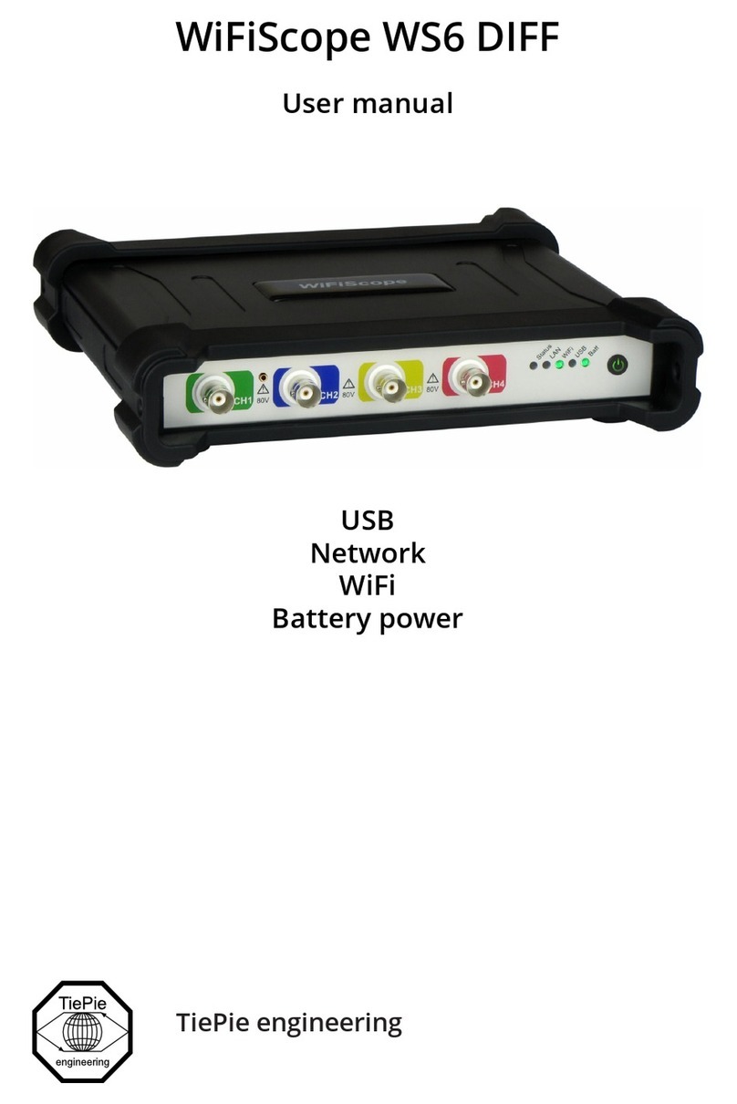
TiePie WiFiScope WS6 User manual
