2.5 In
ut ca
acitor:C1
TUHS25
■To comply with conducterd noise CISPR22-B, EN55022-B, connect capacitor C1 which is 0.1μF
between AC input terminals.
■Use a capacitor with a rated voltage of AC250V which complies with the safety standards.
■If 0.11μF or more capacitor is connected, the discharge resistor is necessary in order to
comply UL60950-1. Please connect the discharge
esistor which satisfy the following formula.
2.6 Varistor:SK1
■In order to comply with IEC61000-4-5 Level 3 (surge immunity), coonnect a surge protective device.
■Overvoltage category changes depending on the location for installing the power supply.
Recommended components is complying to the overvoltage category II.
For example, home electronics and information equipment corresponds the installation category II.
And they are installed the primary part of the equipment which is connected to outlet by power cable.
If installation category III (required to connect distribution panel directly) is required, the varistor
must be bigger than recommended varistor.
Please confirm whether the components comply the standards.
2.7 Out
ut ca
acitor:Co
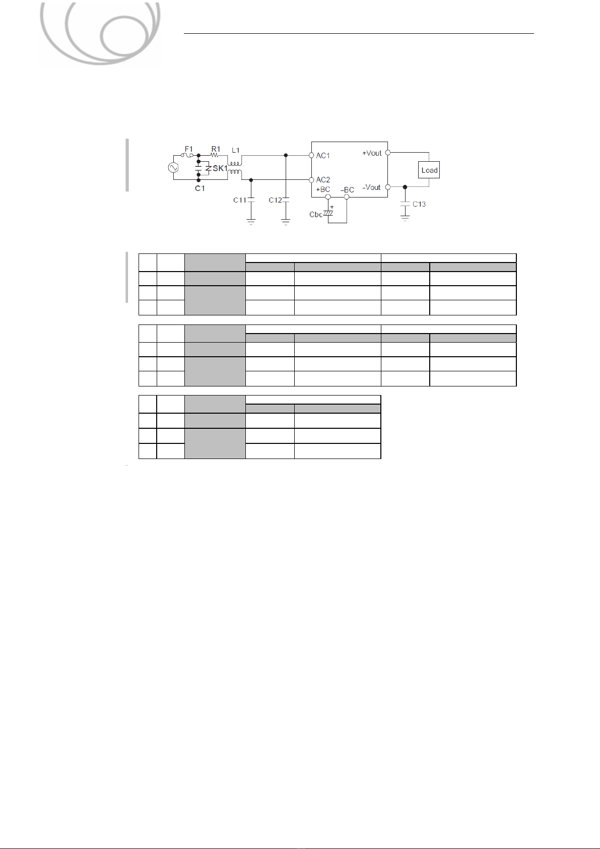
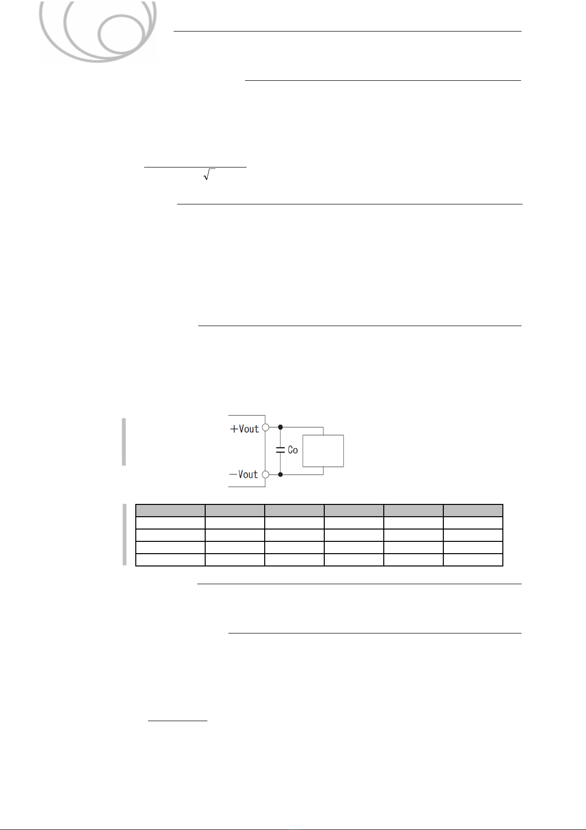
■In the TUHS series, the output capacitor is basically unnecessary. Reduce the ripple voltage or suppress
fluctuation in an output voltage by connecting the output electorolytic capacitor or ceramic capacitor.
The connection example is shown in Fig 2.7.
■When the pulse load is connected, the output voltage will change transiently.
Please check the level of the fluctuation in your situation.
And if the transient output voltage change is not acceptable, please connect the output capacitor Co
Fig.2.7
Connecting Example of
an External Capacitor
to the Output Side
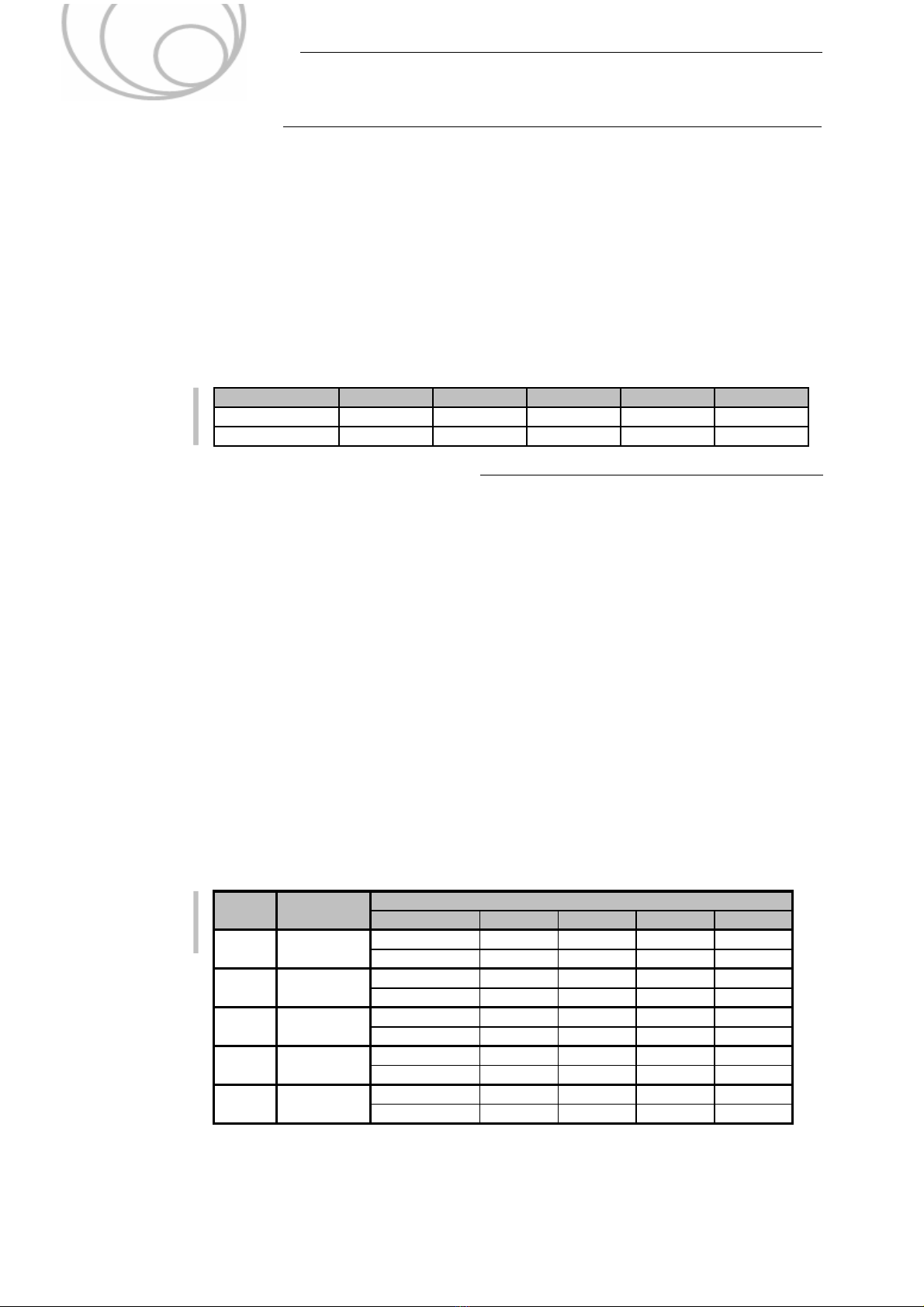
Table 2.5
Recommended
capacitance
Co
2.8 AC line filter:L1
■The commom mode choke coil should be selected with confirmation because there are wire grade
and rated temperature of bobbin.
2.9 Y Ca
acitors:C11
C12
C13
■Please choose safety certified capacitor (Y1, Y2 class approved) to C11 and C12
However,
if secondary circuit is shorted to FG, not connected by capacitor, please choose Y1 class capacitor
as C11 and C12.
■During high voltage test, the voltage applied to C13 is determined by the value of C11, C12 and C13.
Please note the rated voltage of the capacitor. Fomula of the voltage applied to C13 is shown below.
■The noise reduction level depends on the location of the grounding capacitor.
Please connect the capacitor as close as possible to the power supply.
0~330μF
TUHS5 TUHS10 TUHS15
0~47μF 0~150μF
5V 0~100μF 0~100μF
TUHS25
-
A-7
12V 0~470μF0~47μF
Output voltage TUHS3
0~68μF 0~68μF
0~150μF
24V 0~22μF 0~22μF
15V 0~47μF 0~47μF 0~120μF 0~120μF 0~390μF
0~1000μF
0~220μF
42.4)2(Vlog
1
ine1
/
≦
uuC
R
test
CCC CC VV
312111
1211
C13
u
VC13 :Voltage applied to C12
C11,C12 :Y capacitor on the primary side
C13 :Y capacitor on the secondary side
Vtest :Test voltage
R :Discharge resistor
C1:Input capacitance
Vin:Input voltage 120V or 240V[rms]
Load
Applications Manual
TUHS series