enlighted Universal Mounting Case User manual

Page 5 Page 6 93-01651-01 Rev01 Page 1
Copyright © 2016 Enlighted Inc. All rights reserved.
All other brand or product names are trademarks of
their respective companies or organizations.
TechnicalSupport
For questions regardingtheinstallation or operation of
this product,contact Enlighted
TechnicalSupport: support@enlightedinc.com
Company Contact Information
Location: 930 Benecia Ave, Sunnyvale, CA 94085
Phone: +1.650.964.1094
Web: enlightedinc.com
Universal Mounting Case
Installation Instructions
Model: CASE-FS-D22
Universal Mounting Case
Shipped Components
•Enlighted Universal Mounting Case
•Enlighted Mounting Bracket
•½inch Chase Nipple and Locknut
•2 nos. #8 Anchor Screws (Drywall®mount)
•2 nos. #8 Metal Self-tapping Screws (Fixture mount)
Items you may Need
•400BAC Wiremold®Conduit
•18” AWG wire
Tools you may Need
•½” knockout set
•Hand drill
•Wire stripper
•Pliers
•Phillips screwdriver
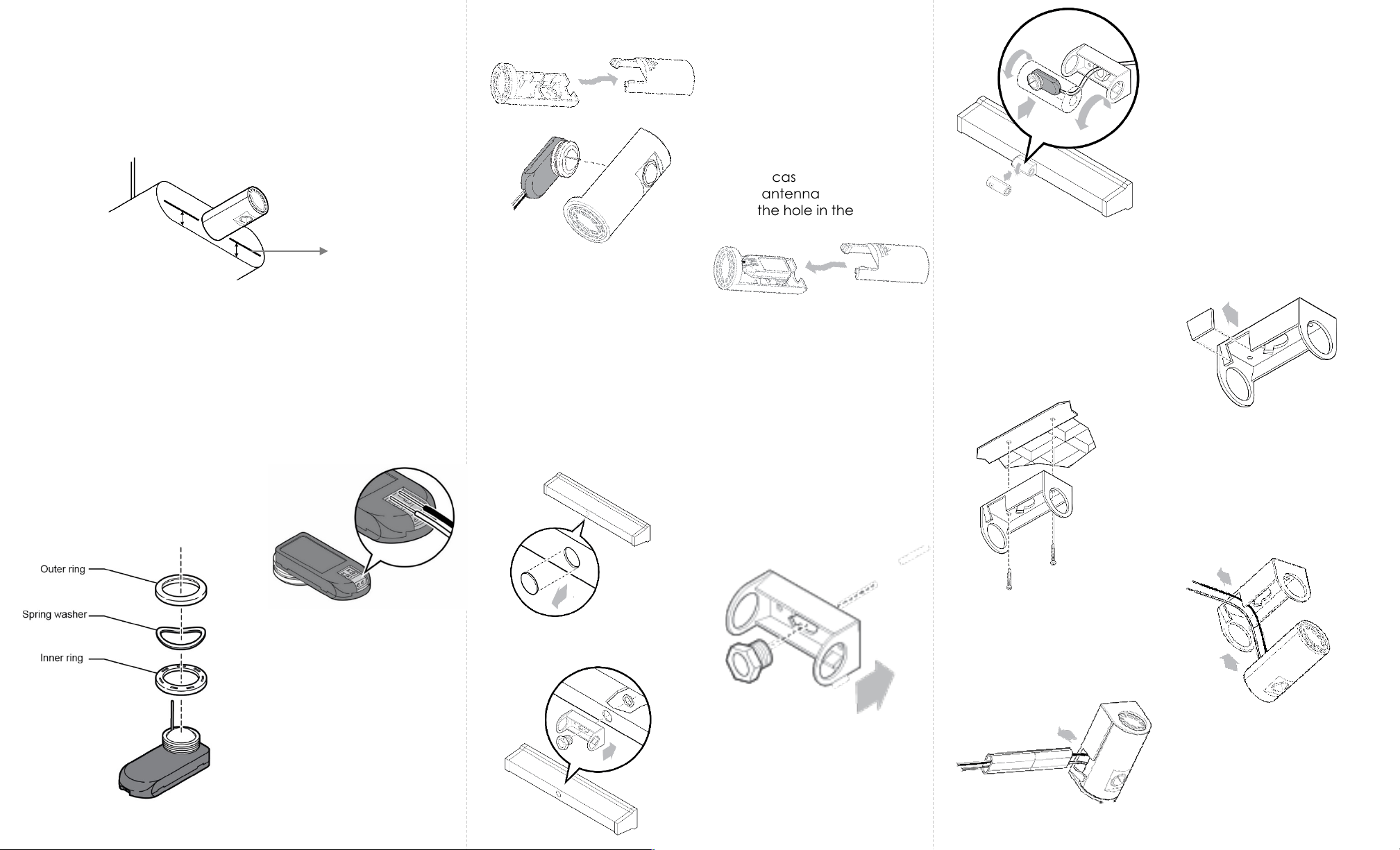
Section 3: Mounting without Bracket
Step 2: Using your thumb or
pliers, push and remove the
knockout of the UMC’s front
case.
Step 3: Insert the ½” Chase
Nipple through the knockout
hole of the UMC’s front case.
Step 4: Insert the sensor into
the UMC case pulling the
cables through the Chase
Nipple. Make sure the lens and
antenna are visible through
the hole in the front.
Step 5: Slide to close the
UMC back cover.
Refer to the design guideline to ensure that the condition is
met. Complete Steps 1, 2, and 3 of Section 1: UMC
Installation before following the procedure below.
Step 6: Mount the UMC to
the fixture by tightening the
Chase Nipple with the
locknut.
Section 4: Wiring the Cables to the LED Driver
To
lamps
From Mains
To Enlighted
Sensors
Step 1: Wire the other end of
the sensor cable to the LED
driver’s XSR connections.
After mounting, rotate the UMC to the required direction and
turn the power on.
Section 5: Rotating the UMC
Step 1: Remove ½” fixture
knockout.
Page 2 Page 3 Page 4
Section 1: Universal Mounting Case (UMC)
Installation
Section 2: Mounting with Bracket
Caution
•Installation and maintenance must be performed by a qualified
electrician in accordance with local, state, and national electrical
codes (NEC) and requirements.
•Turn off all power to the light fixture by switching off the circuit
breaker.
The procedure below shows how to insert the sensor into the
UMC. The UMC can be mounted with bracket (see Section 2)
or without bracket (see Section 3).
Step 4: Insert the sensor into the
UMC front case. Make sure the
lens and antenna are visible
through the hole in the front.
Step 3: Slide to open the UMC
back cover.
Step 5: Slide to close the UMC
back cover until it snaps into
place.
Step 1: Remove the ½” fixture
knockout
You can mount the UMC with bracket to
Option 1: Fixtures with knockout, or
Option 2: Sheetrock and Fixtures without knockout
Option 1: Fixtures with Knockout
Complete Steps 1 through 5 of Section 1: UMC Installation
before following the procedure below.
Step 2: Remove the sensor’s
faceplate comprising the outer,
inner rings and spring washer from
the sensor
Step 2: Insert ½” Chase Nipple
to the inside of the bracket.
Step 3: Connect the bracket to
the fixture by threading the
locknut screw to the Chase
Nipple.
Step 4: Insert the UMC into
the mounting bracket. Pull
the sensor cables through
the Chase Nipple into the
fixture.
Option 2: Sheetrock and Fixtures without Knockout
Design Guidelines
•When the distance from the center of the knockout to the base of
the fixture is greater than 30mm (and lower than 50mm), mount the
UMC without bracket as described in Section 3.
Complete Steps 1 through 5 of Section 1: UMC Installation
before following the procedure below.
Step 1: Locate the tab on
the side of the mounting
bracket and break away
the tab.
Step 2: Mount the bracket to the
fixture or drywall.
Step 3: Insert the UMC into
the bracket. Make sure the
sensor wires exit through the
open slot in the bracket.
The Universal Mounting Case is designed for use with the two-
wire Fixture Mount (FS-D22) sensor.
1. Fixtures: use metal-self
tapping screws
2. Drywall: use anchor screws
Distance from the
base of the fixture
to the center of the
Knock-out
Note: For any reason, if you need
to remove the wires from the
sensor, push down on the tabs with
a pointed device, and remove the
wires while continuing to hold the
tab down.
Step 1: Strip each end of the 18” AWG
two wires leaving 3/8” of exposed wire.
Connect wires to the sensor.
Step 4: only for drywall Insert
the cables through the
Wiremold conduit.
Page 5 Page 6 Page 1
Smart Sensor
Smart Sensor
(SU-4S)
Installation Instructions
Shipped Components
•Smart Sensor
•Anchor Screw
Items you will Need
•Enlighted Sensor Cable: CBL-2-7F
•Enlighted Control Unit
Items you may Need
•Adjustable Mounting Bracket: BRKT-SU-2O-00 F
93-01658-01 Rev04
Model: SU-4S-H/SU-4S-L
FCC ID: AQQ-SU4S
IC: 10138A-SU4S
Copyright © 2016 Enlighted Inc. All rights reserved.
All other brand or product names are trademarks
of their respective companies or organizations.
TechnicalSupport
For questions regardingtheinstallation or operation of this
product,contact Enlighted
TechnicalSupport: support@enlightedinc.com
Company Contact Information
Location: 930 Benecia Ave, Sunnyvale, CA 94085
Phone: +1.650.964.1094
Web: enlightedinc.com
FCC and Industry Canada Compliance Information
This equipment has been tested and found to comply with the limits for a
Class A digital device, pursuant to part 15 of the FCC Rules. These limits
are designed to provide reasonable protection against harmful
interference when the equipment is operated in a commercial
environment. This equipment generates, uses, and can radiate radio
frequency energy and, if not installed and used in accordance with the
instruction manual, may cause harmful interference to radio
communications. Operation of this equipment in a residential area is likely
to cause harmful interference in which case the user will be required to
correct the interference at his own expense.
This device complieswith Part 15 of the FCC Rules and Industry Canada
license-exempt RSS standard(s). Operation is subjectto the following two
conditions:
•this devicemay not cause harmful interference, AND
•this device must accept anyinterference received, including
interference that may cause undesiredoperation.
Changes or modifications not expressly approved by Enlighted Inc.
could void the user's authority to operate the equipment.
Le présent appareil est conforme aux CNR d'Industrie Canada
applicables aux appareils radio exempts de licence.L'exploitationest
autoriséeauxdeux conditions suivantes:
•l'appareil ne doit pas produire de brouillage,ET
•l'utilisateur de l'appareildoitaccepter tout brouillage radioélectrique
subi, même si le brouillage est susceptible d'en compromettre le
fonctionnement.
CE
This device complies with the essential requirements and other relevant
requirements of the R&TTE Directive (1999/5/EC). The equipment is Class 1
radio equipment which can be placed on the market and be put into
service without restrictions in accordance with article 1(3) of Commission
Decision 2000/299/EC (Version July 2014).
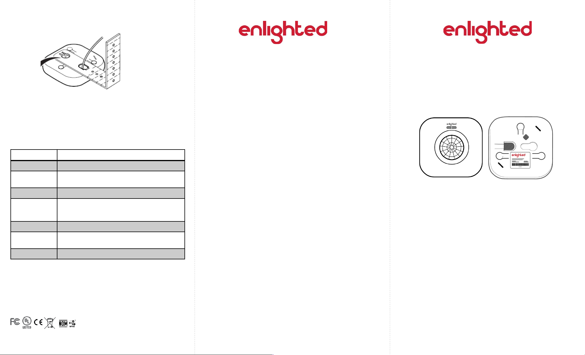
LED Status Description/Solution
LED not on Check power and wiring.
Purple solid All LEDs are on during boot time for 5-6
seconds.
Green blinking Sensor commissioned and working
Red blinking Incompatibility between LED driver and sensor
– Replace LED driver and if not resolved,
replace sensor.
Red solid Faulty sensor – replace sensor.
Green solid Sensor installed, initialized, and
uncommissioned –waiting for discovery.
Blue solid Image being upgraded.
LED Description
Step 4:Slide the Smart Sensor onto the head of the
mounting bracket. See Figure 8.
Figure 8
Front Rear
Step 6: Switch on the circuit breaker to turn the power on.
Step 5: Secure the sensor cable to the bracket or fixture
using cable ties, electrical tape, clips, etc., as appropriate
for the installation.
Page 2 Page 3 Page 4
Installation
Figure 1
Caution
Installation and maintenance must be performed by a qualified
electrician in accordance with local, state, and national electrical
codes (NEC) and requirements.
Step 1: Turn off all power to the light fixture by switching off
the circuit breaker.
Step 2: Mount the Control Unit (CU) in a UL approved
enclosure. Refer to the Control Unit Installation Guide for
installation and wiring instructions. The sensor cable,
terminating in an RJ12 connector, from the CU will need to
connect to the Smart Sensor.
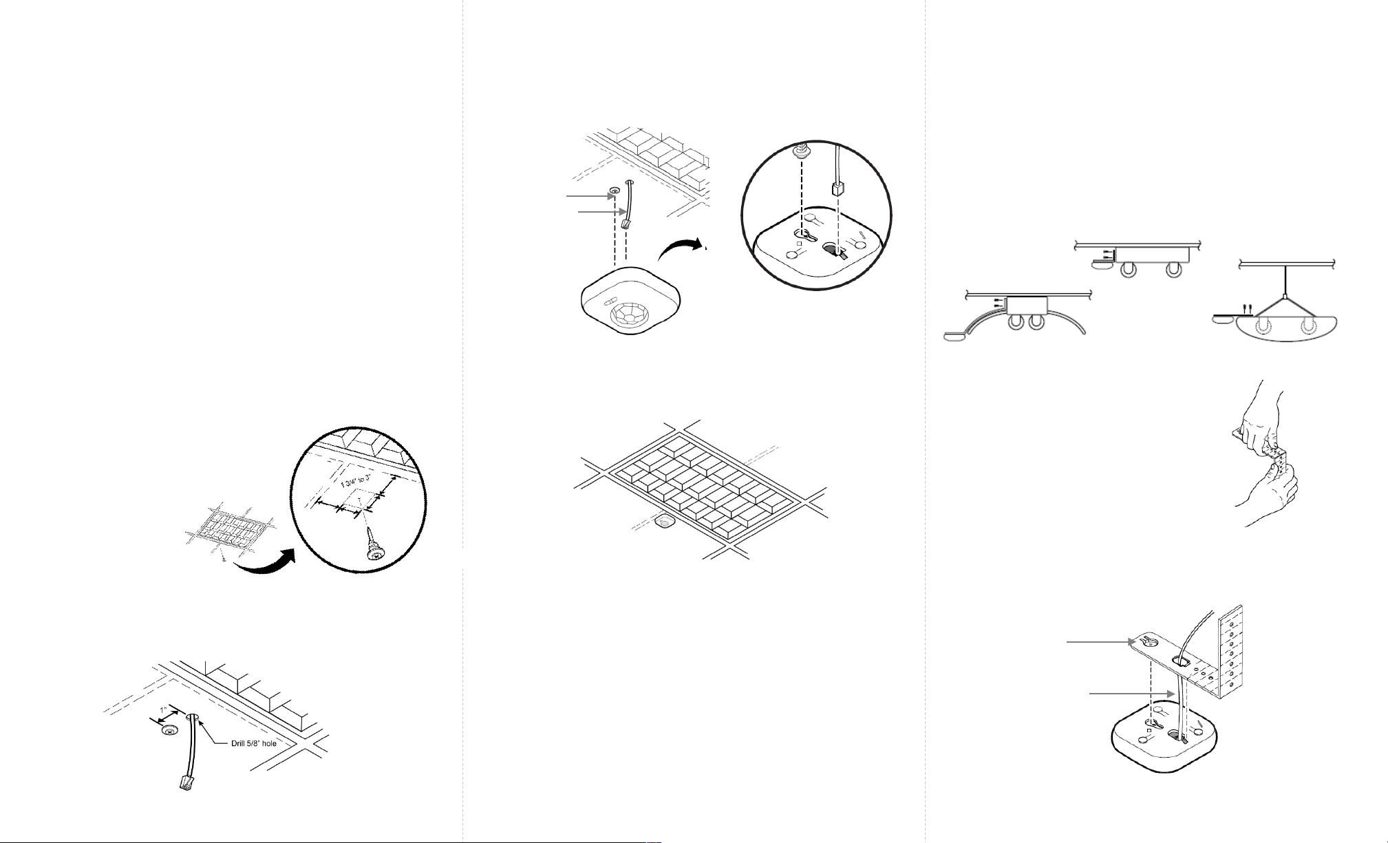
Step 1:Determine the location of
the sensor. Push and rotate the
anchor screw to the tile at that
location.
Step 3: Connect the sensor cable’s RJ12 connector to the
sensor bottom.
Step 4:Align the anchor screw with the slot provided on the
sensor bottom. Slide the Smart Sensor onto the screw head.
Step 5:Slip the excess sensor cable up into the plenum area
and adjust the ceiling tile to the original position.
Step 6: Switch on the circuit breaker to turn the power on.
Figure 4
Anchor Screw
Sensor Cable
The Smart Sensor (SU-4S) should be mounted to the ceiling
tile within a few inches (between 13/4” to 3”) of the lighting
fixture.
The Smart Sensor can be mounted to ceiling tiles using an
anchor screw or to pendant and industrial fixtures using the
adjustable mounting bracket.
Mounting using an Anchor Screw
Mounting using the Adjustable Mounting Bracket
The Smart Sensor (SU-4S) can be mounted on pendant
and industrial fixtures using the mounting bracket.
Step 1: Determine the mounting location of the sensor on
the fixture. To ensure that the view of the sensor is not
obstructed by the fixture, level the sensor to the bottom of
the fixture and provide enough clearance from the fixture.
See examples below.
Step 2:Bend the adjustable
mounting bracket to the required
shape. Fasten the bracket to the
fixture using two 8” screws.
Figure 5
Figure 6
Figure 7
Step 3:Connect the sensor cable’s RJ12 connector from
the CU to the bottom of the Smart Sensor.
Sensor Cable
Mounting
Bracket Head
Step 2: Select a place near the anchor screw for the RJ12
connector of the sensor cable from the CU to exit. Make a
small cut in the ceiling tile for the cable to exit.
Figure 2
Figure 3

Page 5 Page 6 Page 1
Copyright © 2016 Enlighted Inc. All rights reserved.
All other brand or product names are trademarks of
their respective companies or organizations.
TechnicalSupport
For questions regardingtheinstallation or operation of
this product,contact Enlighted
TechnicalSupport: support@enlightedinc.com
Company Contact Information
Location: 930 Benecia Ave, Sunnyvale, CA 94085
Phone: +1.650.964.1094
Web: enlightedinc.com
FCC and Industry Canada Compliance Information
This equipment has been tested and found to comply with the limits
for a Class A digital device, pursuant to part 15 of the FCC Rules.
These limits are designed to provide reasonable protection against
harmful interference when the equipment is operated in a
commercial environment. This equipment generates, uses, and can
radiate radio frequency energy and, if not installed and used in
accordance with the instruction manual, may cause harmful
interference to radio communications. Operation of this equipment
in a residential area is likely to cause harmful interference in which
case the user will be required to correct the interference at his own
expense.
This device complieswith Part 15 of the FCC Rules and Industry
Canadalicense-exempt RSS standard(s). Operation is subjectto the
following two conditions:
•this devicemay not cause harmful interference, AND
•this device must accept anyinterference received, including
interference that may cause undesiredoperation.
Changes or modifications not expressly approved by Enlighted Inc.
could void the user's authority to operate the equipment.
Le présent appareil est conforme aux CNR d'Industrie Canada
applicables aux appareils radio exempts de licence.L'exploitation
est autoriséeauxdeux conditions suivantes:
•l'appareil ne doit pas produire de brouillage,ET
•l'utilisateur de l'appareildoitaccepter tout brouillage
radioélectriquesubi, même si le brouillage est susceptible d'en
compromettre le fonctionnement.
CE
This device complies with the essential requirements and other
relevant requirements of the R&TTE Directive (1999/5/EC). The
equipment is Class 1 radio equipment which can be placed on the
market and be put into service without restrictions in accordance
with article 1(3) of Commission Decision 2000/299/EC (Version July
2014).
Figure 1: Enlighted Smart Sensor Unit
Smart Sensor Unit
Model SU-2O-00
Installation Instructions
Shipped Components
•Smart Sensor (SU-2O-00) Unit
•Anchor Screw
94-00029-02 Rev05
Model: SU-2O-00
FCC ID: AQQ-SU2
IC: 10138A-SU2
CMIIT ID: 2015DJ5439
Page 2 Page 3 Page 4
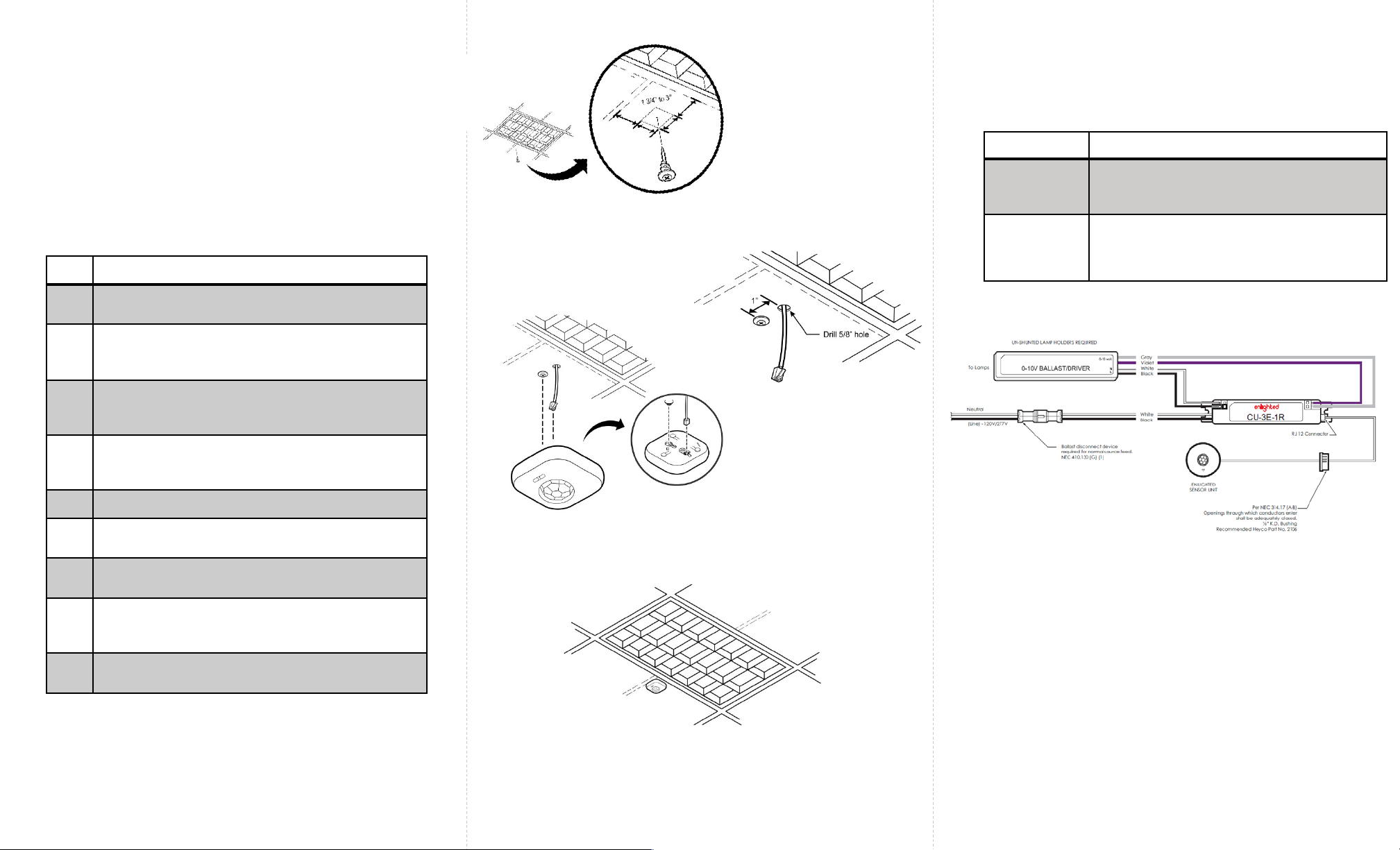
Step Description
1 Turn off all power to the light fixture by switching off
the circuit breaker.
2Mount the Control Unit (CU) in a UL approved
enclosure. Refer to the Control Unit Installation
Guide.
3The Smart Sensor (SU-2O) should be mounted to the
ceiling within a few inches of the lighting fixture and
over the service area of the light. See Figure 2.
4 Select a place for the RJ12 data cable from the CU
to exit and make a small cut in the ceiling tile for
the cable to exit. See Figure 3.
5 Install the Smart Sensor anchor screw (as shown).
6 Connect the RJ12 data cable to the Sensor
(bottom entry). See Figure 4.
7 Slide the Smart Sensor onto the screw head as
shown. See Figure 4.
8 Slip the excess RJ12 data cable up into the plenum
area and adjust the ceiling tile to the original
position.
9 For wiring the sensor to the Control Unit, see Figure
6.
Installation
Figure 6: Wiring Drawing
Caution
•Installation and maintenance must be performed by a
qualified electrician in accordance with local, state, and
national electrical codes (NEC) and requirements.
Troubleshooting
Problem Solution
No green
flashing LED
lights
Verify that the RJ12 cable is plugged into the
Control Unit.
Red, flashing
LED
Possible solutions:
•Replace the RJ12 cable
•Replace the Enlighted Control Unit
To install the Enlighted Smart Sensor Unit, perform the following steps: Figure 2: Sensor Distance from the Fixture
Figure 3: RJ12 Cable Exit
Figure 4: Sensor Connected to Anchor screw
Figure 5: Sensor Installed

Page 5 Page 6 93-02026-01 Rev01 Page 1
Ruggedized Sensor
(SU-5S)
Installation Instructions
Models:
SU-5S-HRW: High Bay, White, Ruggedized Sensor
SU-5S-LRW: Standard Bay, White, Ruggedized Sensor
SU-5S-HRB: High Bay, Bronze, Ruggedized Sensor
SU-5S-LRB: Standard Bay, Bronze, Ruggedized Sensor
FCC ID: AQQ-SU5S
IC: 10138A-SU5S
Ruggedized Sensor (Front and Rear)
Shipped Components
•Enlighted Ruggedized Sensor
•½inch Lock Nut
Supplemental Components
•½inch LB Conduit Body
•½inch Chase Nipple
•Enlighted Control Unit
•Enlighted Sensor Cable
•Cable Coupler: CPL-RJ12
Tools you may Need
•½inch Knock out tool
Copyright ©2018 Enlighted Inc. All rights reserved.
All other brand or product names are trademarks of their
respective companies or organizations.
LED Description
LED Status Description/Solution
LED not on Check power and wiring
Green blinking Sensor is commissioned, working, and has
detected motion. If there is no motion in the
sensor’s field of view, the blinking will stop.
Wave your hands below the sensor to restart
LED blinking.
Red blinking Sensor is not commissioned and has detected
a wiring issue. Check wiring to the Control Unit
(CU) and LED driver.
Red solid Faulty sensor – replace sensor
Green solid Sensor installed, initialized, and not
commissioned –waiting for discovery
Blue solid Sensor received a request to identify itself
FCC and Industry Canada Compliance Information
This equipment has been tested and found to comply with the limits for
a Class A digital device, pursuant to part 15 of the FCC Rules. These
limits are designed to provide reasonable protection against harmful
interference when the equipment is operated in a commercial
environment. This equipment generates, uses, and can radiate radio
frequency energy and, if not installed and used in accordance with
the instruction manual, may cause harmful interference to radio
communications. Operation of this equipment in a residential area is
likely to cause harmful interference in which case the user will be
required to correct the interference at his own expense.
This device complieswith Part 15 of the FCC Rules and Industry Canada
license-exempt RSS standard(s). Operation is subjectto the following two
conditions:
•this devicemay not cause harmful interference, AND
•this device must accept anyinterference received, including
interference that may cause undesiredoperation.
Changes or modifications not expressly approved by Enlighted Inc.
could void the user's authority to operate the equipment.
Le présent appareil est conforme aux CNR d'Industrie Canada
applicables aux appareils radio exempts de licence.L'exploitation
est autoriséeauxdeux conditions suivantes:
•l'appareil ne doit pas produire de brouillage,ET
•l'utilisateur de l'appareildoitaccepter tout brouillage radioélectrique
subi, même si le brouillage est susceptible d'en compromettre le
fonctionnement.
CE
This device complies with the essential requirements and other relevant
requirements of the R&TTE Directive (1999/5/EC) and Radio Equipment
Directive (RED) 2014/53/EU. The equipment is Class 1 radio equipment
which can be placed on the market and be put into service without
restrictions in accordance with article 1(3) of Commission Decision
2000/299/EC (Version July 2014).
Wireless protocol: IEEE802.15.4, Radio Freq: 2400 – 2483.5MHz,
RF TX output power (max): 6dBm
Wireless protocol: IEEE802.15.1, Radio Freq: 2400 – 2483.5MHz,
RF TX output power (max): 6dBm
Company Contact Information
Location: 930 Benecia Ave, Sunnyvale, CA 94085
Phone: +1.650.964.1094
Web: enlightedinc.com
Technical Support: support@enlightedinc.com

Page 2 Page 3 Page 4
The Ruggedized sensor is shipped with the cable
attached to the sensor. The sensor can be mounted to
the fixture using a conduit body and chase nipple or
locknut.
Step 1: De-energize the luminaire.
Step 1: Remove the cover plate of the ½inch LB
conduit body by removing the two screws.
Step 2:Thread the
Ruggedized sensor onto
the LB conduit body.
Step 3: Replace the cover
and two screws on the LB
conduit body.
Chase Nipple
Enlighted
Control Unit
Step 1: Knock out a ½inch hole on the bottom of the
light fixture.
Step 2: Glide the sensor cable through the knockout of
the fixture.
Step 4: Knock out a ½inch hole on the end of the light
fixture.
Step 6:Thread the chase nipple to securely connect
the LB conduit to the fixture.
Caution
Installation and maintenance must be performed by a qualified
electrician in accordance with local, state, and national
electrical codes (NEC) and requirements.
Installation
Mounting using the Conduit Body and Chase
Nipple
Mounting using the Locknut
Step 3: Thread the locknut tightly to secure the sensor to
the fixture.
Step 2: Energize the luminaire and confirm that the
green LED is on solid. Refer to the LED Descriptions on
page 5.
Step 1: Use an RJ45 coupler with an Enlighted Sensor
cable to connect the RJ45 end of the sensor cable to
the connector of the Control Unit (CU).
For wiring connections from the Control Unit to the
sensor, refer to the Control Unit Installation Guide.
Connecting the Sensor Cable to the Control
Unit
Step 5: Mount the Ruggedized Sensor LB Conduit to
the fixture by guiding the sensor cable through the
knock out and chase nipple into the fixture.

Page 5 Page 6 Page 1
Copyright © 2016 Enlighted Inc. All rights reserved.
All other brand or product names are trademarks of
their respective companies or organizations.
TechnicalSupport
For questions regardingtheinstallation or operation of
this product,contact Enlighted
TechnicalSupport: support@enlightedinc.com
Company Contact Information
Location: 930 Benecia Ave, Sunnyvale, CA 94085
Phone: +1.650.964.1094
Web: enlightedinc.com
FCC and Industry Canada Compliance Information
This equipment has been tested and found to comply with the limits
for a Class A digital device, pursuant to part 15 of the FCC Rules.
These limits are designed to provide reasonable protection against
harmful interference when the equipment is operated in a
commercial environment. This equipment generates, uses, and can
radiate radio frequency energy and, if not installed and used in
accordance with the instruction manual, may cause harmful
interference to radio communications. Operation of this equipment
in a residential area is likely to cause harmful interference in which
case the user will be required to correct the interference at his own
expense.
This device complieswith Part 15 of the FCC Rules and Industry
Canadalicense-exempt RSS standard(s). Operation is subjectto the
following two conditions:
•this devicemay not cause harmful interference, AND
•this device must accept anyinterference received, including
interference that may cause undesiredoperation.
Changes or modifications not expressly approved by Enlighted Inc.
could void the user's authority to operate the equipment.
Le présent appareil est conforme aux CNR d'Industrie Canada
applicables aux appareils radio exempts de licence.L'exploitation
est autoriséeauxdeux conditions suivantes:
•l'appareil ne doit pas produire de brouillage,ET
•l'utilisateur de l'appareildoitaccepter tout brouillage
radioélectriquesubi, même si le brouillage est susceptible d'en
compromettre le fonctionnement.
Figure 1: Plug Load Controller, Locknut, and Sticker
Plug Load Controller
Model PC-01-20
Installation Instructions
Shipped Components
•Plug load controller (and ½inch locknut)
•MAC address sticker
Tools You May Need
•Wire stripper
Supplies You May Need
•Wire nuts (or connectors)
•Junction box (j-box)
•Two Conductor plus ground 12 AWG solid wire cable
•Three Conductor plus ground 12 AWG solid wire cable
•Clamps
93-01142-01 Rev05
Model: PC-01-20
FCC ID: AQQ-PC-01-20
IC: 10138A-PC0120
Troubleshooting
Page 2 Page 3 Page 4
Caution
•Installation and maintenance must be performed by a
qualified electrician in accordance with local, state, and
national electrical codes (NEC) and requirements.
Problem Solution
LED is not on when
the device is
powered
1) Check to see that power is present
from the circuit panel.
2) Check the wiring, if LED does not
come on, then replace the
device.
Step Description
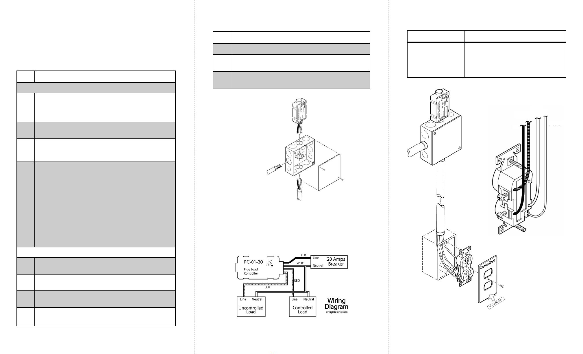
J-box Install (see Figure 2)
1Punch out a ½inch knock out from the j-box and
insert the threaded end of the plug load controller.
Secure the plug load controller to the j-box with the
supplied locknut.
2(Main Feed) Feed the j-box with (3) 12 AWG
conductors. (Hot, Neutral, and Ground)
3Connect the j-box with (4) 12 AWG conductors that
run from the j-box to the receptacle wall box.
(Hot, Switched Hot, Neutral, and Ground)
4Using wire nuts (or wire connectors):
a) Connect the hot wire from the main feed to the
black wire of the plug load controller.
b) Connect the neutral wire from the main feed to
the white wire of the plug load controller and the
neutral wire that feeds through to the receptacle.
c) Connect the red wire of the plug load controller
to the switched hot wire that feeds through to the
receptacle.
d) Connect the blue wire of the plug load controller
to the hot wire that feeds through to the
receptacle.
e) Connect all ground wires to the j-box.
Receptacle Install (see Figure 4)
5Break the connection on the “hot side” of the
receptacle between the two outlets.
6 Connect the neutral wire to the neutral connection
on the receptacle.
7Connect the switched hot wire to the hot side of the
“controlled outlet”.
8Connect the hot wire to the hot connection of the
“uncontrolled outlet” (always powered).
Installation Steps
Installation Steps (Continued)
Step Description
9 Install the receptacle in the wall box
10 Attach a receptacle faceplate that distinguishes the
controlled outlet.
11 Attach the included MAC address sticker on the
faceplate.
Figure 2: J-box with plug load controller, showing main
feed and wiring to receptacle.
Figure 3: Wiring Diagram
Figure 4: Receptacle wiring
Main feed:
•Hot
•Neutral
•Ground
Receptacle feed:
•Hot
•Switched Hot
•Neutral
•Ground
Hot
Neutral
Switched
Hot
Ground

Page 5 Page 6 Page 1
Copyright © 2016 Enlighted Inc. All rights reserved.
All other brand or product names are trademarks of
their respective companies or organizations.
TechnicalSupport
For questions regardingtheinstallation or operation of
this product,contact Enlighted
TechnicalSupport: support@enlightedinc.com
Company Contact Information
Location: 930 Benecia Ave, Sunnyvale, CA 94085
Phone: +1.650.964.1094
Web: enlightedinc.com
FCC and Canada Compliance Information
This device complies with Part 15 of the FCC Rules and with Industry
Canada license-exempt RSS standards. Operation is subject to the
following two conditions: (1) this device may not cause harmful
interference, and (2) this device must accept any interference received,
including interference that may cause undesired operation. Changes or
modifications not expressly approved by Enlighted Inc. could void the user's
authority to operate the equipment. This equipment generates, uses, and
can radiate radio frequency energy and, if not installed and used in
accordance with the instruction manual, may cause harmful interference
to radio communications. Operation of this equipment in a residential area
is likely to cause harmful interference in which case the user will be required
to correct the interference at his own expense.
Le présent appareil est conforme aux CNR d'Industrie Canada applicables
aux appareils radio exempts de licence. L'exploitation est autorisée aux
deux conditions suivantes : (1) l'appareil ne doit pas produire de brouillage,
et (2) l'utilisateur de l'appareil doit accepter tout brouillage radioélectrique
subi, même si le brouillage est susceptible d'en compromettre le
fonctionnement.
Under Industry Canada regulations, this radio transmitter may only operate
using an antenna of a type and maximum (or lesser) gain approved for the
transmitter by Industry Canada. To reduce potential radio interference to
other users, the antenna type and its gain should be so chosen that the
equivalent isotropically radiated power (e.i.r.p.) is not more than that
necessary for successful communication.
Conformément à la réglementation d'Industrie Canada, le présent émetteur radio
peut fonctionner avec une antenne d'un type et d'un gain maximal (ou inférieur)
approuvé pour l'émetteur par Industrie Canada. Dans le but de réduire les risques de
brouillage radioélectrique à l'intention des autres utilisateurs, il faut choisir le type
d'antenne et son gain de sorte que la puissance isotrope rayonnée équivalente
(p.i.r.e.) ne dépasse pas l'intensité nécessaire à l'établissement d'une communication
satisfaisante.
This radio transmitter IC: 10138A-GW2 has been approved by Industry
Canada to operate with the antenna types listed below with the maximum
permissible gain and required antenna impedance for each antenna type
indicated. Antenna types not included in this list, having a gain greater
than the maximum gain indicated for that type, are strictly prohibited for
use with this device.
Le présent émetteur radio IC: 10138A-GW2 a été approuvé par Industrie Canada pour
fonctionner avec les types d'antenne énumérés ci-dessous et ayant un gain admissible
maximal et l'impédance requise pour chaque type d'antenne. Les types d'antenne
non inclus dans cette liste, ou dont le gain est supérieur au gain maximal indiqué, sont
strictement interdits pour l'exploitation de l'émetteur.
CE
This device complies with the essential requirements and other relevant
requirements of the R&TTE Directive (1999/5/EC). The product is compliant
with the following standards and/or other normative documents - EN 62479,
ETSI EN 301 489-1-17, EN 300 328 and EN 60950-1
•The equipment is Class 1 radio equipment which can be placed on the
market and be put into service without restrictions in accordance with
article 1(3) of Commission Decision 2000/299/EC (Version July 2014).
Gateway (GW)
Model GW-2-01
Installation Instructions
Figure 1: Gateway Unit (front and back)
Shipped Components
•EnlightedGateway
•Two #6 - 1” screws with standoffs
•Antenna: Nearson S151AH-07826 2.4GHz Swivel
Antenna with 5dBi, 50 Ohm
Tools You May Need
•#2 Philips screwdriver
Supplies You May Need
•Cat-5e or Cat-6 data cable with RJ45 (conforming to
TIA/EIA 568-B) connectors between the gateway
(GW) and PoE Ethernet switch
Model: GW-2-01
FCC ID: AQQ-GW2
IC: 10138A-GW2
CMIIT ID: 2015DJ5440
93-01246-01-01 Rev05

Page 2 Page 3 Page 4
Caution
•Disconnect all power before installation or service.
•Installation and maintenance must be performed by a qualified
electrician in accordance with local, state, and national electrical
codes (NEC) and requirements.
Problem Solution
No LED on the
Gateway (GW) is
on or blinking.
•Verify the Cat-6 cable
betweenthe PoEport on
theEthernet switch and
the Enlighted Gateway
has not been damaged.
•Check that the RJ45
connectors on each end
of the Cat-6 cable are
completely inserted.
•Verify that the PoE
Ethernet switchis powered
and functioning properly.
RedLED on the GW
is on continuously.
Replace the Gateway.
Red LED on the
GW is blinkingat
a slow rate and
thegreen LED is
off.
This is the expected blink
pattern before the
Energy Manager is
connected to the PoE
Ethernet Switch and
made operational.
Red LED on the GW
is off and the green
LED is blinking
rapidly.
This is the expected blink
pattern after the Energy
Manager is connected to
the PoE Ethernet Switch
and made operational,
and before the GW is
commissioned.
Troubleshooting
Figure 2: Attach the unit to the wall on screws
with the antenna pointing up
Figure 4: Wiring Diagram for PoE switch and GW
Step Description
1Determine a location for the GW. The Cat-5e
or Cat-6 data cable from the PoE Ethernet
switch MUST be less than 300 feet. Ideally, the
GW will be at the same elevation as the
sensors it communicates with. It MUST be
visible so that it’s LEDs can be seen for
troubleshooting. Because it uses wireless
communication with sensors, it SHOULD be
placed to maximize the number of sensors
that are near it.
2Select a location for the RJ45 connector
(conforming to TIA/EIA 568-B) of the data
cable to exitthewall or ceiling. Make a small
circular cut(roughly 11/16th of an inch in
diameter) in thewall or ceiling for the RJ45
connector.
3Install the two #6, 1” screws two inches apart.
4Slide the GW onto the screws as shown in
Figures 2 and 3.
5If on the wall, point the antenna straight up.
If on the ceiling, point antenna straight down.
6Insert the RJ45 connector on one end of the
data cable into the GW.
7 Routethedata cable to the PoEEthernet
switch and insert the RJ45 connector into a
powered PoE port (see Figure 4).
8Power on the PoE Ethernet switch and check
for the “PoE Active” LED to be green for the
port connecting the GW.
Installation Steps (both wall & ceiling mounts)
Note: After a Gateway has been commissioned, the red
LED is off and the green LED blinks at a slow rate.
Figure 3: Attach the unit to the ceiling on screws
with the antenna pointing down
PoE Active
LEDs

Page 5 Page 6 Page 1
Copyright © 2016 Enlighted Inc. All rights reserved.
All other brand or product names are trademarks of
their respective companies or organizations.
TechnicalSupport
For questions regardingtheinstallation or operation of
this product,contact Enlighted
TechnicalSupport: support@enlightedinc.com
Company Contact Information
Location: 930 Benecia Ave, Sunnyvale, CA 94085
Phone: +1.650.964.1094
Web: enlightedinc.com
FCC and Industry Canada Compliance Information
This equipment has been tested and found to comply with the limits
for a Class A digital device, pursuant to part 15 of the FCC Rules.
These limits are designed to provide reasonable protection against
harmful interference when the equipment is operated in a
commercial environment. This equipment generates, uses, and can
radiate radio frequency energy and, if not installed and used in
accordance with the instruction manual, may cause harmful
interference to radio communications. Operation of this equipment
in a residential area is likely to cause harmful interference in which
case the user will be required to correct the interference at his own
expense.
This device complieswith Part 15 of the FCC Rules and Industry
Canadalicense-exempt RSS standard(s). Operation is subjectto the
following two conditions:
•this devicemay not cause harmful interference, AND
•this device must accept anyinterference received, including
interference that may cause undesiredoperation.
Changes or modifications not expressly approved by Enlighted Inc.
could void the user's authority to operate the equipment.
Le présent appareil est conforme aux CNR d'Industrie Canada
applicables aux appareils radio exempts de licence.L'exploitation
est autoriséeauxdeux conditions suivantes:
•l'appareil ne doit pas produire de brouillage,ET
•l'utilisateur de l'appareildoitaccepter tout brouillage
radioélectriquesubi, même si le brouillage est susceptible d'en
compromettre le fonctionnement.
CE
This device complies with the essential requirements and other
relevant requirements of the R&TTE Directive (1999/5/EC. The
equipment is Class 1 radio equipment which can be placed on the
market and be put into service without restrictions in accordance
with article 1(3) of Commission Decision 2000/299/EC (Version July
2014).
Two-wire Fixture Mount Sensor (FSD22)
Two-wire Fixture Mount
Sensor (FSD22)
Installation Instructions
Shipped Components
•Enlighted fixture mount sensor
Tools You May Need
•Wire stripper
Supplies You May Need
•18 AWG solid copper wire, rated >= 300V
93-01144-02 Rev08
Model: FS-D22
FCC ID: AQQ-CS-D2
IC: 10138A-CSD2

Page 2 Page 3 Page 4
Installation
LED Description
Figure 4
Note: For any reason, if you need to remove the two wires,
push down on the tabs of the sensor with a pointed device,
and remove the wires while continuing to hold the tab down.
Sensor Antenna
To Enlighted
sensor To
lamps
Figure 1
Figure 2
LED Status Description/Solution
LED not on Check power and wiring
Purple solid All LEDs are on during boot time for 5-6 seconds
Green
blinking
Sensor commissioned and working
Red blinking Incompatibility between LED driver and sensor –
Replace LED driver and if not resolved, replace
sensor.
Red solid Faulty sensor – replace sensor
Green solid Sensor installed, initialized, and
uncommissioned –waiting for discovery.
Blue solid Image being upgraded.
Figure 3 Figure 5
From Mains
The two-wire Fixture Mount sensor is designed to mount in a ½
inch trade size knockout. All parts of the sensor are inside the
lighting fixture except for the outer ring. (See Figure 4). This
sensor is for use with the Philips XSR driver.
Step 1: Switch off the circuit breaker supplying power to the
light fixture.
Step 2: Determine the location for the sensor in the fixture.
Step 3: Remove an existing ½inch knockout or cut a hole in
the fixture.
Step 4: Measure the distance between the sensor’s installation
location and the LED XSR driver.
Caution
Installation and maintenance must be performed by a qualified
electrician in accordance with local, state, and national electrical
codes (NEC) and requirements.
Step 5: Cut two lengths of 18 AWG solid wire that are at least
this measured length plus one inch. Strip each end of the two
wires leaving 3/8 inch of exposed wire.
Step 6: Insert one end of the pair of wires into the LED XSR
driver’s connections wire holes. See Figure 2.
Step 7: Remove the outer ring
from the sensor by unthreading
it. Keep the spring washer and
inner ring on the sensor.
Step 9: Close the light fixture and restore power to the fixture.
Step 8: Insert the sensor assembly into the knockout that was
cut out of the light fixture. Thread the outer ring back on the
sensor. Tighten firmly, but do no over tighten. If you have a
thick fixture, do not use the inner ring.
Note: Make sure that the sensor antenna passes through the
knock out and does not get caught in the rings or assembly.
LED Driver
Sensor Antenna
Page 5 Page 6 Page 1
Copyright © 2016 Enlighted Inc. All rights reserved.
All other brand or product names are trademarks of
their respective companies or organizations.
TechnicalSupport
For questions regardingtheinstallation or operation of
this product,contact Enlighted
TechnicalSupport: support@enlightedinc.com
Company Contact Information
Location: 930 Benecia Ave, Sunnyvale, CA 94085
Phone: +1.650.964.1094
Web: enlightedinc.com
FCC and Industry Canada Compliance Information
This equipment has been tested and found to comply with the limits
for a Class A digital device, pursuant to part 15 of the FCC Rules.
These limits are designed to provide reasonable protection against
harmful interference when the equipment is operated in a
commercial environment. This equipment generates, uses, and can
radiate radio frequency energy and, if not installed and used in
accordance with the instruction manual, may cause harmful
interference to radio communications. Operation of this equipment
in a residential area is likely to cause harmful interference in which
case the user will be required to correct the interference at his own
expense.
This device complieswith Part 15 of the FCC Rules and Industry
Canadalicense-exempt RSS standard(s). Operation is subjectto the
following two conditions:
•this devicemay not cause harmful interference, AND
•this device must accept anyinterference received, including
interference that may cause undesiredoperation.
Changes or modifications not expressly approved by Enlighted Inc.
could void the user's authority to operate the equipment.
Le présent appareil est conforme aux CNR d'Industrie Canada
applicables aux appareils radio exempts de licence.L'exploitation
est autoriséeauxdeux conditions suivantes:
•l'appareil ne doit pas produire de brouillage,ET
•l'utilisateur de l'appareildoitaccepter tout brouillage
radioélectriquesubi, même si le brouillage est susceptible d'en
compromettre le fonctionnement.
CE
This device complies with the essential requirements and other
relevant requirements of the R&TTE Directive (1999/5/EC). The
equipment is Class 1 radio equipment which can be placed on the
market and be put into service without restrictions in accordance
with article 1(3) of Commission Decision 2000/299/EC (Version July
2014).
Figure 1: Enlighted Room Control (ERC2)
Room Control (ERC)
Model WS-2-00
Installation Instructions
Shipped Components
•Enlighted Room Control version 2 (ERC2)
•Usage card
•Back plate (with captive screws in place)
•Cover plate
•Two tapping screws
•Two 6-32 machine screws
Tools You May Need
•Phillips screw driver
•Flat head screw driver
93-01140-01 Rev06
Model: WS-2-00
FCC ID: AQQ-WS-2-00
IC: 10138A-WS200
CMIIT ID: 2015DJ5479
Troubleshooting
Page 2 Page 3 Page 4
Caution
Installation and maintenance must be performed by a
qualified electrician in accordance with state, local, and
national electrical codes (NEC) and requirements.
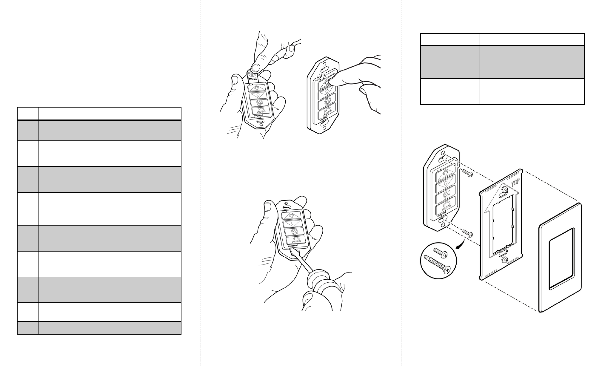
Figure 5: Mounting Sequence
Problem Solution
LEDs do not flash
when a is button
pressed
The energy in the battery may
have drained. Check, and if
needed, replace the battery
(see Figure 4)
Buttons do not
easily move
when pressed
Return unit for replacement
Figure 4: Opening the ERC2’s case to access the battery
Step Description
1 Separate, if needed, the cover and back
plates.
2Remove the plastic pull tab from ERC2 to
allow the battery to come in contact with the
terminals. (See figure 2)
3 Press each button and verify that both the
green and red LEDs flash and that the button
moves smoothly. (See figure 3)
4 If the LEDs do not flash when a button is
pressed, then check, and if needed, replace
the battery. The battery is accessed after
opening the case as shown in figure 4.
5Position the ERC2 on either the wall or on a
junction box with the LEDs on the top and the
Enlighted logo on the bottom. (See Figure 5)
6 Use the provided tapping screws (or machine
screws for a junction box) to attach the ERC2
to the wall.
7Align the back plate (with the arrow pointing
up) to the ERC2. Affix the back plate to the
ERC2 by firmly tightening both captive screws.
8Snap on the cover plate with the arrow (on its
back side) pointing up.
9 Save usage card for room occupants.
Installation Steps
Both Wall and Junction Box Mounting
Figure 2: Remove plastic
tab to allow battery to
power unit
Figure 3: Press each
button to verify operation
and that LEDs flash
Page 5 Page 6 93-01219-02 Rev01 Page 1
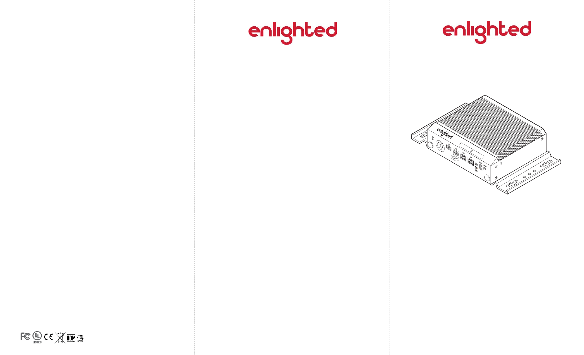
Energy Manager
Installation Instructions
Energy Manager
Shipped Components
•Enlighted Energy Manager Server
Items you may Need
•Phillips Screwdriver
FCC and Industry Canada Compliance Information
This equipment has been tested and found to comply with the limits
for a Class A digital device, pursuant to part 15 of the FCC Rules.
These limits are designed to provide reasonable protection against
harmful interference when the equipment is operated in a
commercial environment. This equipment generates, uses, and can
radiate radio frequency energy and, if not installed and used in
accordance with the instruction manual, may cause harmful
interference to radio communications. Operation of this equipment
in a residential area is likely to cause harmful interference in which
case the user will be required to correct the interference at his own
expense.
Copyright © 2016 Enlighted Inc. All rights reserved.
All other brand or product names are trademarks of
their respective companies or organizations.
TechnicalSupport
For questions regardingtheinstallation or operation of
this product,contact Enlighted
TechnicalSupport: support@enlightedinc.com
Company Contact Information
Location: 930 Benecia Ave, Sunnyvale, CA 94085
Phone: +1.650.964.1094
Web: enlightedinc.com
Page 2 Page 3 Page 4
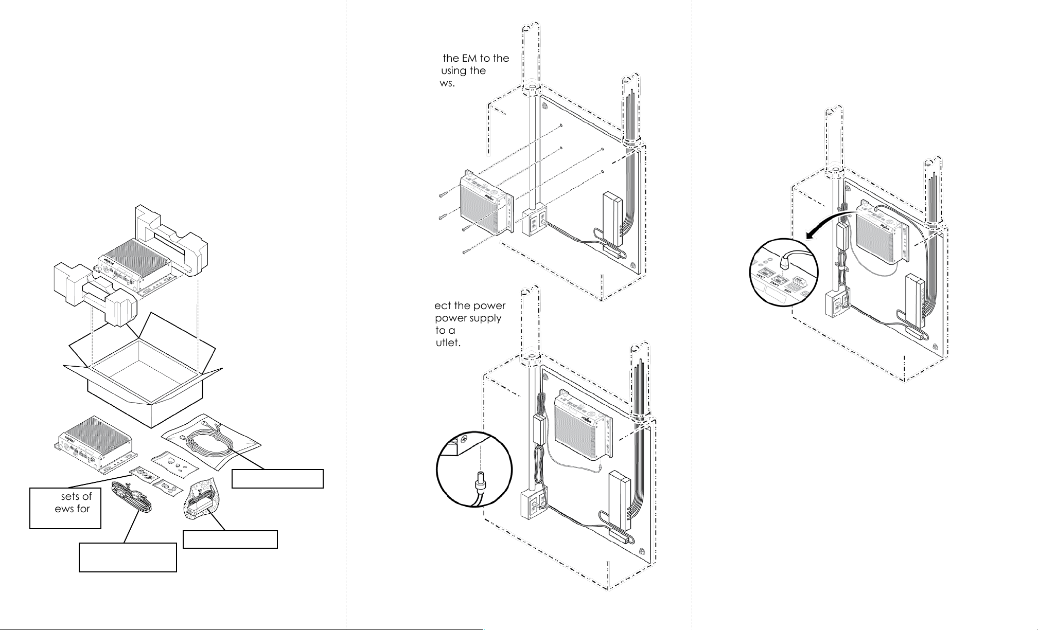
The procedure below shows how to install the Energy Manager.
The Energy Manager (EM) can be installed on a backer board,
which can be inside or outside of an enclosure.
Step 1: Unbox the Energy Manager (EM).
Caution
Installation and maintenance must be performed by a
qualified electrician in accordance with local, state, and
national electrical codes (NEC) and requirements.
Step 2: Attach the EM to the
backer board using the
mounting screws.
Step 3: Connect the power
cable to the power supply
and plug it into a
receptacle outlet.
Step 4: Use an Ethernet cable to connect LAN2 port on the
EM to a standard port on the PoE switch.
Step 5: Tie the extra-length of the cables using tie wraps
and/or hold downs.
Power supply
Power cable for
power supply
Two sets of
screws for
mounting
Ethernet cable

Page 5 Page 6 Page 1
Copyright © 2018 Enlighted,Inc. All rights reserved.
All other brand or product names are trademarks of
their respective companies or organizations.
TechnicalSupport
For questions regardingtheinstallation or operation of
this product,contact Enlighted
TechnicalSupport: support@enlightedinc.com
Company Contact Information
Location: 930 Benecia Ave, Sunnyvale, CA 94085
Phone: +1.650.964.1094
Web: enlightedinc.com
Fixture Mount Control Unit
Model CU-4E
Installation Instructions
Shipped Components
•Enlighted Fixture Mount Control Unit
Items you will Need
•Two mounting screws, as appropriate for mounting
the Control Unit to the inside of the luminaire
93-02297-01 Rev.03
FCC and Industry Canada Compliance Information
This equipment has been tested and found to comply with the limits
for a Class A digital device, pursuant to part 15 of the FCC Rules.
These limits are designed to provide reasonable protection against
harmful interference when the equipment is operated in a
commercial environment. This equipment generates, uses, and can
radiate radio frequency energy and, if not installed and used in
accordance with the instruction manual, may cause harmful
interference to radio communications. Operation of this equipment
in a residential area is likely to cause harmful interference in which
case the user will be required to correct the interference at his own
expense.
CAN ICES-003 (A)/NMB-003 (A)
CE
This device complies with the essential requirements and other
relevant requirements of CISPR 24, CSIPR 32 in the EMC Directive
2004/108/EMC and is compliant with the following standards:
EN61000-6-2, EN61000-6-4. In addition the device is compliant with
the IEC 61347-2-11 safety standard for Lamp Control gear.
Models: CU-4E-FM,
CU-4E-FMH
Open Energy
Mgt. Eqp t.
3WG4

Page 2 Page 3 Page 4
Installation Steps
Step 1: Switch off the circuit breaker supplying power to
the light fixture.
Step 2: Open the fixture cover and remove the cover for
the ballast cavity. The ballast and its wiring should now be
visible.
Step 3:Utilizing a voltmeter, verify that power is off to the
ballast. If power is present, stop work, identify, and switch
off the circuit breaker.
Step 4: Place the Control Unit (CU) in the desired location
and secure it with mounting screws. If desired, the CU
mounting tab can be shortened by snapping off the tab
at the notch on the AC input side of the CU.
Step 5: Disconnect the “Hot” wire (Line) of the ballast
from the power input wire.
Step 6: Connect the power input “Hot” wire (Line) to the
Control Unit black Wago Lin (Line In) connector.
Step 7: Connect the ballast power input “Hot” wire to the
Control Unit red Wago Lout (Line Out) connector.
Step 8: Connect the power input (Neutral) wire to either one
of the two white Wago N(Neutral) connectors on the CU.
Step 9: Connect the ballast (Neutral) wire to either one of
the two white Wago N(Neutral) connectors on the CU.
Step 10: Bend wires into place such that the ballast cover
can easily be reattached.
Step 11: Install the RJ45 sensor cable between the Control Unit
and the Enlighted sensor. Do not use RJ12 cable as it may
damage the sensor port. Refer to the corresponding Sensor
Installation Guide for connecting the cable between the
sensor and the Control Unit (CU).
Completing the Installation
Step 2: Connect the gray wire (-) from the dimming ballast to
channel A gray Wago terminal on the Control Unit. Repeat for
channel B if required.
Step 1: Connect the violet wire (+) from the dimming ballast to
channel A violet Wago terminal on the Control Unit. Repeat for
channel B if required.
Step 1: If the sensor is mounted outside of the luminaire, use
a snap bushing in the knockout hole on the lighting fixture to
route and protect the sensor cable. If the sensor is mounted
within the luminaire, then bushing is not needed.
Step 2: Install the cover for the ballast cavity and apply
power to the newly wired lighting fixture.
Step 3: The lights should turn on to full bright state, and then
may cycle or dim based on the sensor commissioning status
or programming.
The Control Unit (CU-4E) can connect to two dimming
ballasts on two separate channels (channels A and B) for
“Tunable White” applications. If using both dimming
channels, gently break the tab above channel B. For single
channel dimming, use channel A terminals only. For multiple
dimming drivers on the same channel the dimming wires may
be connected in parallel (violet to violet and grey to grey) for
all drivers on that channel.
Installation and maintenance must be performed by a
qualified electrician in accordance with state, local, and
National Electrical Codes (NEC) and requirements.
The Fixture Mount Control Unit must be installed in a UL-
rated fixture or enclosure rated for this application.
Caution
Additional Installation Instructions for Use with a
Dimming Ballast
This manual suits for next models
13
Table of contents


