PilotAware OGN-R User manual

Upgrading an Existing OGN Ground Station to Rebroadcast Glider Locations on 869.5MHz.
December 2019.
1
Introduction
Why should you upgrade an existing OGN Ground station to Rebroadcast Glider Locations
on 869.5MHz? When upgraded the Ground Station is termed an OGN-R Station. -R signifying
data rebroadcast
In upgrading to OGN-R you will be helping the gliding and General Aviation Communities
(Foot-launched, Gliding, Microlights and Powered Aircraft) in Europe and the UK to improve
the interoperability of the various Electronic Conspicuity systems available today. These are
ADSB, FLARM, PilotAware, Mode- S and Mode-C. By installing an OGN-R station at your
location (Club or House) you will be contributing to the ground network that will assist the
interoperability between systems by up-linking situational awareness data to PilotAware
equipped aircraft.
In addition as part of the installation you will get a real time, on site Virtual RADAR station
that can be displayed on a computer, monitor or TV screen. This will via the OGN-R upgrade
show all GA aircraft equipped with Flarm, PilotAware and ADSB in real time and also Mode-S
equipped aircraft with a small MLAT† delay. †Note this is currently operational in the UK
where we have sufficient MLAT data available from 360RADAR. In mainland Europe we are
growing the capability.
We don’t expect you to do it all alone. Whilst stocks last PilotAware will provide you with
the Radio Bridge and software free of charge and will also provide a Pi2B, free of charge, if
you are currently running an earlier model. You will need to provide the rest, as described
in this document, which you can do for less than £150.
An OGN-R ground based station will provide about a 30-40Km area of coverage to help
aviation safety around your site.
You can do everything yourself or we will help. ogn@pilotaware.com
Interested? Let’s go!

Upgrading an Existing OGN Ground Station to Rebroadcast Glider Locations on 869.5MHz.
December 2019.
2
Table of Contents Click in the link.
Introduction .................................................................................................................... 1
OGN-R PilotAware Uplink ................................................................................................ 2
What Parts are Required.................................................................................................. 3
Installation High Level Diagram........................................................................................ 4
Upgrade .......................................................................................................................... 4
Location for the Electronics.............................................................................................. 4
Location for the 2 new antennas (PiotAware Tx Rx and 109MHz Rx) ................................. 5
Making up the Co-Axial Cables......................................................................................... 5
Connecting the Electronics............................................................................................... 6
Locating and Naming your Site .................................................................................................7
Location Information ...............................................................................................................7
Downloading and installing OGN-R Software.................................................................... 8
Configuring the Software for your Specific Location. ........................................................ 8
Shellinabox..............................................................................................................................8
Possible Problems...........................................................................................................11
Testing to see if Your Station is Working.................................................................................11
Checking for captured real time data......................................................................................12
Checks to show that your OGN-R station is Working OK.......................................................... 13
Other Apps to show that the OGN-R is working ...................................................................... 14
For Advanced users ........................................................................................................14
Updating the Software on Your OGN-R Installation .........................................................14
The PilotAware 360Radar Virtual RADAR Station.............................................................15
Introduction .......................................................................................................................... 15
Connecting to PilotAware Radar360 Virtual RADAR ................................................................15
Addendum .....................................................................................................................17
Parts Required to build an OGN-R uplink.........................................................................17
OGN-R PilotAware Uplink
Thank you for offering to help to expand the OGN-R Network to provide additional safety
for powered aircraft and gliders alike by up-linking FLARM and Mode-S equipped aircraft co-
ordinates to PilotAware equipped aircraft. Thereby making gliders more visible at low cost.

Upgrading an Existing OGN Ground Station to Rebroadcast Glider Locations on 869.5MHz.
December 2019.
3
To help you with the costs of upgrading or installing a new OGN-R uplink, PilotAware Ltd
will, whilst stocks last, provide a PilotAware Radio Bridge and software FREE OF CHARGE.
This is available to supporters who want to increase the OGN-R network both in the UK and
mainland Europe. In addition, if required, PilotAware will load and configure the software
to make it even easier for you. If you want to know more contact us at
mailto:OGN@pilotaware.com and apply for your free stuff.
Upgrading an existing OGN station to OGN-R functionality does not require a high level of
technical knowledge. The OGN-R is a technical innovation but the highly technical parts do
not need to be understood by the installer or host. These step by step instructions are
provided. We will of course be available on line to help. Most of all, you will be making
history and its fun.
What Parts are Required
1. A Raspberry Pi Single Board Computer (Pi 2B) Provided Free of Charge if required
2. A PilotAware Radio Bridge Provided Free of Charge
3. An SD Memory Card
4. A n 869.5MHz PilotAware Antenna
5. A 1090MHz Antenna
6. Coaxial cables to connect the antennas to the electronics.
7. An RTLSDR software defined Radio for the 1090MHz reception and detection.
8. A Raspberry Pi Mains-to 5.2V, 2.1A, power supply
9. A simple mechanical timer to turn off the power once a day between 0200 - 0300
10. A Pigtail to connect the Co-Axial cable to the 1090MHz RTL-SDR
11. Antenna mounts to support the antennas
1. The PilotAware Antenna. This is used to transmit and receive data to aircraft
fitted with PilotAware units operating at 869.5MHz. The PilotAware antenna is
connected to the PilotAware Radio Bridge mounted on the Raspberry pi via a co-axial
cable and an SMA connector.
2. A 1090MHz receive only Antenna is also used for the OGN-R station. This antenna
collects 1090MHz transmitted data ie ADSB and Mode-S transmissions for use by
360RADAR to contribute to their network and provide Mode-S data for use in
PilotAware Mode-S/3D reception. All data collected is also used to provide a feed for
a local Virtual RADAR screen which will show local PilotAware, FLARM, ADSB traffic
in real time and Mode-S traffic with MLAT delay.
The feed from the 1090MHz Antenna, is connected to the Raspberry Pi via a software
defined receiver (SDR). This can be inserted in any of the USB slots but by convention is
located in the bottom left hand USB slot on the raspberry Pi unit with the Ethernet socket to
the left. The location chosen is then configured in the set up as described later on.
*Note using the latest software the location of the 2 RTLSDRs can be chosen to be located in any slot at
the configuration stage. This is because some RTLSDR’s are larger than others and this allows easier
mechanical fitment. However the slot used must be chosen in the configuration.

Upgrading an Existing OGN Ground Station to Rebroadcast Glider Locations on 869.5MHz.
December 2019.
4
A list of equipment and suppliers is available at the end of this document any queries
mailto:OGN@pilotaware.com.
Installation High Level Diagram
The above diagram is provided as a visualisation of the hardware installation which can be modified for
your specific installation. The Raspberry Pi, the Antenna 3 (Flarm 868MHZ Rx), the cable and the Flarm
RTLSDR will already be installed in your existing OGN-R Station.
Upgrade
The upgrade of the OGN consists of
1. Selecting a dry location for the electronics with access to 240V and Internet. †
1. Installing the additional external antennas at a suitable location.
2. Making up and running the additional 2 low loss coaxial cable from the antennas to
the electronics location.
3. Connecting the parts together
4. Installing and configuring the software for your specific site. (Location, Site Name
Password and Email Address)
5. Power up and test.
Location for the Electronics
•The location for the electronics should be as close to the antennas as practically
possible. As short a distance as possible is preferred but up to 10 metres is OK. This
is to minimise the losses in the Co-Axial cable. Note up to 16 metres has been shown
to work using the recommended HDF 400 or equivalent 50 ohm coaxial cable.
OGN-RRaspberryPi
andPilotAwareRadio
BridgeCombination
Antenna1
PilotAwareTx/Rx
869.5MHz
HDF400Coax
HDF400Coax
HDF400Coax
N-Type
Connector
N-Type
Connector
N-Type
Connector
N-Type
Connector
N-Type
Connector
Pigtail†
Pigtail†
Pigtail†SMAtoMCX
N-Typeto
SMA
converter
N-Typeto
SMA
converter
Antenna2
1090MHzRx
Antenna3
FLARM 868MHzRx
RTLSDRRPi
TopLeftSMA
socket
RTLSDRRPi
BottomLeft
SMAsocket
N-Typeto
SMA
converter
N-Type
Connector
PilotAware
Bridge
SMA
connector
RJ45
Connector
EthernetCable Router
Power5.2V1.2A
TypicalOGN-R
InstallationDiagram.
(individualinstallations
mayvary) Voltage
Converter
240VAC

Upgrading an Existing OGN Ground Station to Rebroadcast Glider Locations on 869.5MHz.
December 2019.
5
•Mains power is required within 2 metres of the Raspberry Pi for the Raspberry Pi
mains to 5.2v 2.5A power supply.
•The mains power supply to the Raspberry Pi power converter should be via a
switched mechanical timer set to turn the power off during the night.. (Please
choose a random time around 23:00 to 0400) This will ensure a timely daily reboot
of the system. 30 minutes downtime is enough From January 2019, the OGN-R
software includes an automatic check for and download of available new software.
Be aware that if you suffer regular power failures the timing of the mechanical timer
will drift by the time of the power outage so a periodic check on the timers is
advisable.
•An Ethernet cable is required to connect the Raspberry Pi to the router. This can
generally be as long as required. Max 100 metres
•If the installation is a long way from the router or it is not easy to run a direct link
ethernet cable, then the LAN can be extended over the mains using a power line
carrier device such as devolo which has been used successfully on several locations.
https://www.devolo.co.uk
Location for the 2 new antennas (PiotAware Tx Rx and 109MHz Rx)
•The antennas should be positioned vertically and as high as possible avoiding
obstacles that would get in the way of line of sight transmission and reception, such
as walls. The antennas should be a minimum of 30cm apart. Further away the better.
Only the PilotAware antenna is transmitting. (It transmits at 869.5MHz so will not
affect or be affected by local VHF voice antennas)
•Each and every installation will be bespoke. A wide variety of antenna mounts are
commercially available from Screw fix, Tool Station and other suppliers in the UK. A
list of typical mounts is supplied at the end of these instructions.
•The recommended antennas are supplied with Female N-Type connectors.
Making up the Co-Axial Cables
•HDF 400 (double shielded low loss coaxial cable) or equivalent and N-Type
connectors should be used for all antennas for maximum efficiency. Although a
smaller cable like RG8X or LM240 can be used for short reaches.
•HDF400 cable is fairly thick and will require a suitable Crimp tool to make off the
connectors. If you are just doing the one installation, it may be cheaper to have
these cables made up commercially. A crimp tool is about £15.
•One Male and One Female N-Type connector is required for each cable.
•The Male N-type connector on the Co-Axial cable should be offered to the Female N-
Type connector on the antenna and the connectors screwed firmly together. The
joint should be weather-proofed using self-amalgamating tape.
•This should be repeated for the second antenna.
•The Co-Axial cables should then be dressed to the location of the electronics which
should be as close as practically possible. (Take care that you know which cable goes
to which antenna by labelling the loose ends.)
•A suitable short pigtail may be required to connect the N-type connector to the RTL-
SDR dongle. This will either be a male SMA or Mcx connector depending on the
RTLSDR chosen.

Upgrading an Existing OGN Ground Station to Rebroadcast Glider Locations on 869.5MHz.
December 2019.
6
Connecting the Electronics
A good tip is to mount the electronic onto a small wall board or box to secure the units
without putting stress onto the components or cables. The cables can then be secured with
cleats.
The electronics are connected to the following interfaces.
The diagram below is representative only. Your installation may change depending on the
RTL-SDR’s and connector types used. The following instructions therefore will not be the
same for all installations.
1. An N Type to SMA Converter is screwed firmly into the Female N-Type connector of
each Coaxial cable.
2. The coaxial cable connected to the PilotAware (869.5MHz) Antenna (shown on the
left of the following diagram) is connected firmly to the SMA connector on the
PilotAware Bridge mounted as a Hat on top of the Raspberry Pi via the PIO
connector.
3. You will already have a Coaxial cable connected to the FLARM Antenna which is
connected to an existing RTL-SDR. For convention this is connected in the top left
hand USB slot when seen with the ethernet slot on the left hand side .
4. The Coaxial cable connected to the 1090MHz Antenna is connected to the RTL-SDR
in the bottom left hand USB slot.
5. The Ethernet cable is connected to the Ethernet port of the Raspberry Pi, with the
other end connected to a free port on the local router.
6. The Raspberry Pi power supply is connected to the mains supply via the mechanical
timer set to provide power during daylight hours.
7. DO NOT AT THIS POINT TURN THE POWER ON.
8. Make sure that the complete set up is located firmly and that there is no bending
moments or other stress on any of the components.
9. Cable cleats and other fixtures should be used to affect a neat installation.
10. The hardware is now set up.

Upgrading an Existing OGN Ground Station to Rebroadcast Glider Locations on 869.5MHz.
December 2019.
7
†Note the above picture uses low power RTLSDR dongles available from Stratux as these
easily fit the available space. Others may be used if suitable. The RTL-SDR used to connect to
your existing Flarm antenna will probably be larger than this as it will have an in built
temperature controlled oscillator. The RTL-SDR used for the detection of 1090MHz does not
necessarily need a temperature controlled oscillator. If the RTL-SDR’s available are larger
they can be configured to be inserted in other USB sots in the configuration program
described later. If necessary external aluminium enclosures provided with the dongles
should be removed.
Locating and Naming your Site
Location Information
You will need to have the existing unique location information for your station to hand.
This will include
The station name
The Latitude
The Longitude
The Geoidsepar
RadioBridge
RaspberryPi
Case
DC5.2V2.1A
Power
Coaxial
Cableto
PAW869.5
Antenna
NoteTheFLARMantennaMUST
beconnectedtotheRTL-SDR
connectedtotheTOPLEFT
HANDUSBSOCKETandiffitted
the1090MHzantennaMUSTbe
connectedtotheBOTTOMLEFT
HANDUSBSOCKETwiththe
Ethernetcabletotheleft
Ethernetcableto
Router
Coaxial
Cableto
FLARM
Antenna
Coaxial
Cableto
1090MHz
Antenna
RTL-SDR
TopFLARM
Bottom
1090MHz

Upgrading an Existing OGN Ground Station to Rebroadcast Glider Locations on 869.5MHz.
December 2019.
8
Downloading and installing OGN-R Software.
To make the installation of the OGN-R as easy as possible new software has been
produced that steps you through the installation process.
You will need to note your existing station name its latitude, longitude and the height of the
antenna above mean sea level. These will be required to configure the OGN-R software.
1. Download the latest disk image for the combined OGN/PAW software from
http://pilotaware.lode.co.uk/downloads/OGN/PilotAware-OGN.latest.zip
2. This will download a zip file with a name similar to PilotAware-OGN.20190713 into
the downloads folder of your computer. The numbers after the ‘.’ Indicate the
version date.
3. Place all the individual unzipped contents of this file (not the folder) into a
formatted Micro SD Card. This will require the use of an SD card holder to fit the
Micro SD card into the SD slot on your computer.
4. The root of the SD card should contain the following folders
- defaults
- os
- overlays
and many other files.
5. When you have downloaded all the files, eject the card from your computer and load
the SD card into SD card holder at the end of the Raspberry Pi card, power up and
leave for about 20 minutes to allow the files to unpack and self-configure.
6. Whilst the software is unpacking, there will be a permanent red light (Power) and a
flashing green light (Disc access) on the raspberry pi. DO NOT INTERUPT THE POWER
SUPPLY AS THIS WILL CORRUPT THE SOFTWARE.
7. You can watch the unpacking progress by attaching a TV or a monitor to the Pi via an
HDMI cable. When it has finished the prompt, ‘pi’will be seen. The software has now
downloaded and has unpacked successfully.
Configuring the Software for your Specific Location.
Shellinabox
The OGN-R software has been developed to make the installation as simple as possible.
There are 3 ways to connect to the software to configure the program for your unique
location.
1. The most direct way to input the required data is to connect a monitor and keyboard
to the Pi. This is done by connecting the Monitor to the HDMI port and the keyboard
to any USB port.

Upgrading an Existing OGN Ground Station to Rebroadcast Glider Locations on 869.5MHz.
December 2019.
9
2. Alternatively, connect a computer to the specific IP address allocated locally by
your router to your OGN-R unit. To locate the specific ip address allocated by your
router to the raspberry pi (host name ognpaw) connect to the router via a wired
Ethernet or WiFi connection. Connect to the router by typing in 192.168.0.1 into
your browser. Note this may differ depending on your broadband provider.
3. Once connected to your router you need to locate the IP address that has been
allocated to the Raspberry Pi (host name ognpaw) of your OGN-R. To get the actual
IP address allocated to the Raspberry Pi you may have to use an advanced menu that
is password protected. See your local router instructions. For example, a UK Sky
network router generic log in is ‘admin’ and the password is ‘sky’. Others will differ.
Then choose LAN IP Set Up. For example, if the IP address allocated for your unit
with the default hostname ‘ognpaw’is 192.168.0.200 then you will connect via
192.168.0.20.The allocated address (in this case 192.168.0.20) will vary from router
to router.
Also, please note if the router is powered down it may allocate a different IP address.
This is called dynamic IP allocation. This can be overcome by giving the OGN-R a fixed
IP address.
4. Additionally, the OGN-R software has been developed so that you can run a shell
from within a web browser. Google Chrome or Firefox is recommended.
When connected on the same network as the Pi, navigate to http://ognpaw.local
Note this is NOT https://. You will probably get a prompt to say that this sites is
insecure - ignore this and continue to the address. Not all routers allow you to do
this as they do not resolve the allocated IP address to the default host name of
ognpaw.local. In this case you will have to revert to using the allocated ip address as
shown in the previous paragraph 3.
With each connection type, when connected correctly, you will see the following
prompts. Your response is the characters in red
login: pi (Ensure this is pi NOT PI or Pi)
password: 12345678 (This is the default Password. It is strongly recommended to change it
during the configuration). (Note the password will not appear in the command
line as you are typing it.)
pi@ognpaw: $ cd rtlsdr-ogn (changes the directory to where the required files are located)
pi@ognpaw: /rtlsdr-ogn ./PilotAware-OGN.config.sh (this runs the configuration program)
Note please make sure that the syntax is correct if it is not you will be prompted that there
is an error.
You may get the message sudo: unable to resolve host ognpaw–ignore
this.
Wait a while and if the RTLSDR’s are connected you will see Found 2 SDR’s and you will
be told in which of the four USB slots they are located.
The first SDR is required for FLARM 868MHz detection. By convention this is put in the top
left hand USB slot with the RJ45 Ethernet socket to the left. The second SDR is for the

Upgrading an Existing OGN Ground Station to Rebroadcast Glider Locations on 869.5MHz.
December 2019.
10
1090MHz detection. This is used to provide a 1090MHz feed to 360Radar and the virtual
RADAR server.
The screen will look something like this though this may change with later revisions of SW
which is dynamic.
(15:18:48) FILESYS : Mount RW
Stopping Services
Do not plug in or remove any SDR dongles whilst this configuration script is running.
It is strongly advised to have the SDR's plugged in and then reboot the Pi before running this configuration
script.
Found 2 SDR's:
Raspberry Pi 2 Model B Rev 1.1
USB Port Top Left : dongle ID=1and is currently allocated to OGN/FLARM reception on 868Mhz
USB Port Bottom Left : dongle ID=0and is currently allocated to ADS-B reception on 1090Mhz
USB Port Top Right : SDR detected
USB Port Bottom Right: SDR detected
1 dongle is currently configured for OGN and the other is configured for ADS-B reception
Do you wish to change the dongle configuration [y/n]:
[Note if you want to move from convention (say because the dongles are too big), then you
can put the dongles in other slots but you will have to re-boot the system. You will then
have to declare which dongle you want to be allocated to which frequency 868Mhz for
Flarm or 1090MHz for ADSB and Mode-C/S]. You must then also ensure that correct
antennas are connected to the correctly tuned RTL-SDR. The Flarm antenna will be your
existing one.
Check that the dongles are in the right place (FLARM in top left and 1090MHz in bottom left
with the Ethernet cable to the left) or where you have re-allocated them, then answer (n)
Now continue to follow the instructions. You will be prompted to provide a new Password
please do this so no one else can hack your system –they will. Record your password, it
can’t be recovered by you or us. Consequently a complexly new manual upgrade will be
required
You will be prompted to change the host name from (ognpaw). Do not change this unless
absolutely necessary and you know what you are doing, otherwise answer (n)
You will be prompted to provide a new Name for your ground station Answer (y) and
replace it with in your existing OGN name 7 letters max).
You may have seen that OGN uplinks are prefixed with PW i.e. PWEBGW. You do NOT need
to prefix your name with PW this is done automatically.
The program will require you to input the Latitude, Longitude, Altitude, Height AMSL and
Geoid of your location.
Using the values for your existing site.
Provide Station Latitude (change default value to the value of your station) Return
Provide Station Longitude (change default value to the value of your station). Return
Upgrading an Existing OGN Ground Station to Rebroadcast Glider Locations on 869.5MHz.
December 2019.
11
Provide Station Height AMSL (change default value to the value of your station). Return
Provide Geoid Return
Note the PilotAware Configuration program will calculate the GEOID and suggest what it
is. Use this unless you have a more accurate GEOID figure
The software will then install and calibrate the RTLSDR FLARM radio receiver.
This will take about 90 seconds and it will step through 0dB to +50dB. Stages
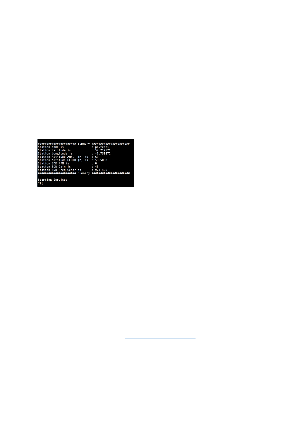
If all is well a banner will then be shown with your configuration as shown below.
Following this and after up to 10 minutes to connect to the server it will show Starting
Services. The OGN-R station is now up and running.
pi@ognpaw:~/rtlsdr-ogn
Possible Problems
a) If the SW cannot see the FLARM antenna through the RTL-SDR dongle the software
program proceeds through the calibration very quickly, This, means that there is no
physical connection from the RTLSDR dongle to the FLARM antenna. Suspect the co-axial
cable, pigtail or RTLSDR connection. Make sure all connections are secure and that the
inner pins of the Co-axial cable connectors are mating properly. If you have an SWR
meter available the impedance should be 40-60 ohms and the VSWR between 1 and 2
b) The calibration routine searches for GSM signals for the antenna and RTLSDR calibration.
Therefore, you may have difficulty in capturing data in low GSM signal strength areas. So
long as some data (Say 6-10 sites) is collected this is OK. This part of the setup is only
used to calculate the frequency offset to be used for the particular antenna.
c) If after a successful calibration the program states that it cannot “start service”, this may
be that it cannot get through your broadband router to the internet and hence to the
OGN servers. If this is the case suspect your router or internet connection.
When connected to the OGN servers via the internet, it can take up to 10 minutes for the
station to appear on the OGN map http://ognrange.unseen.org
Testing to see if Your Station is Working
Once your station has registered with the OGN servers it will be displayed on the OGN map.

Upgrading an Existing OGN Ground Station to Rebroadcast Glider Locations on 869.5MHz.
December 2019.
12
To check this, connect to the internet and navigate to http://ognrange.unseen.org
When connected, to can locate your site type in PWName (where Name is the first 7 digits
of your OGN-R Station Name), into the Box “Showing All Choose”. Navigate to the
approximate area in Europe where your station is located and your site should show up on
the map. As the days’ progress, you will see all of the targets that you have captured build.
Choosing PWName, will show the PilotAware units captured.
Choosing Name (without PW at the Front) will show the FLARM units captured.
Capturing targets at 50Km+ for PWName and 60Km+ for Name is normal. Unless you are on
a geographic flat plane this will not be symmetrical due to local obstructions etc. It will take
several weeks to capture enough data to determine the range of your station.
There is a second useful URL https://www.dropbox.com/s/0n5emkw4nm85sw1/ogn-
r.txt?dl=0
This can be accessed to see if your station is up or down, what software it is running and the
last time it received a response to poll for its status.
Note the OGN-R software will auto update. The best way of doing this is to install a simple
mechanical timer (the type used to turn standard lamps on and off) between the mains and
the RPi power supply, so that the Raspberry pi is powered down between midnight and
0400 hrs. ON powering up it will install the new software if available.
Checking for captured real time data.
Whilst connected to the same network as the pi using a modern browser such as Chrome or
Safari type in the allocated ip address. This will be something like 192.168.0.14, BUT WILL BE
SPECIFIC TO YOUR INSTALLATION.
A matrix screen similar to this should appear.

Upgrading an Existing OGN Ground Station to Rebroadcast Glider Locations on 869.5MHz.
December 2019.
13
The instantaneous, cumulative number and type of aircraft detected will be recorded
Key
OK
Number of confirmed targets recorded.
NG
Targets Rejected due to not meeting defined requirements.
ICAO
The ICAO of the aircraft being detected
Type
Ogn - PilotAware - MLAT
Age*
Age of MLAT data in seconds
AMB*
RND = Rounded ACT = Actual
Distance (KM)
Distance from the OGN-R station
Altitude
Altitude in feet.
Uplink
What is triggering the uplink.
•Only provided in the UK in Mode-S/3D trial areas
Checks to show that your OGN-R station is Working OK.
To check that the OGN-R station is working, power up a PilotAware unit in the immediate
location and from the PilotAware unit you should see:
1. The OGN-R station will be recorded in the top right hand of the PilotAware RADAR
Screen.
2. The OGN-R station will be shown as an ICON in the centre of the RADAR screen. (You
must have selected show ground stations on your PilotAware unit using the latest SW
release 20190721)
3. The OGN-R station will appear in the list in the Rosetta Traffic Page
4. The PilotAware with ICAO number, Altitude and Distance will be recorded on the
OGN-R Virtual RADAR Screen.

Upgrading an Existing OGN Ground Station to Rebroadcast Glider Locations on 869.5MHz.
December 2019.
14
5. FLARM equipped targets will be shown on PilotAware RADAR and also on EasyVFR
SkyDemon etc. if the Flight Bag is connected.
6. For the advanced user. There are 3 main processes running.
(i) ogn-rf
(ii) ogn-decode
(iii) pilotaware
each of these provide logging which can be used for diagnosis. They are accessed in
the following way
Note To see logging from ogn-rf, use the following command. $ nc localhost 50000
If there ae no error reports then all is good. Error reports will indicate faults.
Note To see logging from ogn-decode use the following command. $ nc localhost 50001
This will display captured data from FLARM
Note To see logging from Pilotaware, Display Flarm, P3i & MLAT $ nc localhost 50002
Other Apps to show that the OGN-R is working
There are several Apps that can be used to show historical and real time data from your
OGN-R site. On each site zoom into your local area and check your site progress.
The Open Glider Network at http://ognrange.onglide.com
Spot the Gliders at http://live.glidernet.org
Advice is also available at forum.pilotaware.com
For Advanced users
The disk image is operated in a safe mode, which means it cannot normally be over written
In order to gain write access type.
$ sudo /root/mount rw.bash
To write protect type.
$ sudo /root/mount ro.bash
The software is running as a service to start/stop the service
$ sudo service rtlsdr-ogn stop
$ sudo service rtlsdr-ogn start
Updating the Software on Your OGN-R Installation
Note onec you have installed the latest software then software and operating system
updating is done automatically.

Upgrading an Existing OGN Ground Station to Rebroadcast Glider Locations on 869.5MHz.
December 2019.
15
If, however you want for force a software update then use the following script.
pi@ognpaw:~ $ cd rtlsdr-ogn
pi@ognpaw:~/rtlsdr-ogn $
pi@ognpaw:~/rtlsdr-ogn $ ./PilotAware-OGN.update.sh
The PilotAware 360Radar Virtual RADAR Station.
Introduction
If you have installed all 3 antennas PilotAware, FLARM and 1090MHz then you will be able
to use a browser equipped computer or tablet to drive a Virtual RADAR display for your
clubhouse or any other location. This display can be a computer itself, a monitor or large TV.
The PilotAware 360Radar Virtual RADAR station is for entertainment only and currently
cannot be used for air traffic control or any form of guidance. PilotAware 360 Radar, will
give you real time data (negligible delay) of all PilotAware, FLARM and ADSB equipped
aircraft in your region. This will be typically 30-60Km for PilotAware and FLARM equipped
aircraft and 40- 100Km for ADSB equipped aircraft depending on the height of the target
aircraft. In addition, Mode-S aircraft that are being interrogated by Secondary Surveillance
Radar (SSR) will also be shown on the screen with the normal limitations of multilateration
(MLAT). These are
(i) The target Mode-S aircraft must have been interrogated by Primary RADAR. This
may not happen below 800ft.
(ii) There will be a delay of between 1 and 10 seconds for the MLAT trace to be
refreshed.
To gain access to PilotAware 360Radar Virtual Radar you will need to have OGN-R software
revision 20190210 or later. If you have software that is earlier than this, you will need to
undertake a full manual software download in to ensure that the correct Operating System
is being used.
Connecting to PilotAware Radar360 Virtual RADAR
•If you have maintained the recommended hostname of ognpaw, using a modern
Browser Safari, Chrome, Firefox etc connect to the same local network (LAN) as the
ground station and in the browser search bar type in ognpaw.local. You should get a
screen that looks something like the following screenshot. There may be more rows
indicating more local MLAT aircraft but this is not important.
(Note if your router or cable modem does not resolve ognpaw.local to the IP address
allocated to the host ognpaw then you will have to type in the allocated IP address. This will
be something like 192.168.0.40. Of course the 192.168.0.40 bit will be specific to your
router and will be different. Log into your router admin maintenance to find out what it is.
Upgrading an Existing OGN Ground Station to Rebroadcast Glider Locations on 869.5MHz.
December 2019.
16
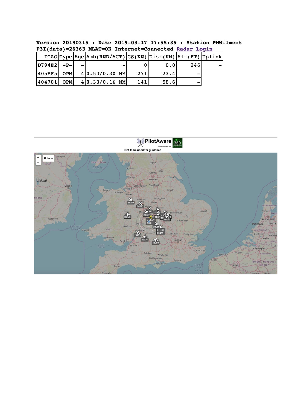
On the second row, a URL entitled Radar will be seen. Click on this to activate PilotAware
360 Radar Virtual RADAR.
After about 10 –20 seconds, a screen resembling this will appear.
At the top left corner, there is a menu which when activated allows configuration of the
screen. The menu has several options.
It is not intended to go through each menu here as they are self-explanatory. However, at
the high level they are:
General
This allows the user to configure the centre of the map on your current or other location
and chose the units for the heights speeds etc.
Map
Allows the user to apply distance rings choose colours etc

Upgrading an Existing OGN Ground Station to Rebroadcast Glider Locations on 869.5MHz.
December 2019.
17
Aircraft
This allows a multitude of parameters to be set for the target aircraft detected.
List
This allows the aircraft list to be configured
Filters
The filters page allows the user to generate a range of filters for customising the display.
Full operating instructions are available at as
http://www.virtualradarserver.co.uk
Please remember as good as PilotAware VRS is this must not be used for air traffic
management, control or guidance.
Addendum
Parts Required to build an OGN-R uplink
The parts below are recommended but can be substituted for other suitable parts.
Part
Supplier
Raspberry Pi 2B
P3i Radio Bridge
Case
RTLSDR 2 required
(1) for FLARM
(2) for 1090
These are available from
https://www.ebay.co.uk/itm/UK-Software-Defined-Radio-Receiver-RTL-SDR-with-RTL2832-
ADC-Chip-SMA-F-

Upgrading an Existing OGN Ground Station to Rebroadcast Glider Locations on 869.5MHz.
December 2019.
18
Connector/163855712001?_trkparms=aid=111001%26algo=REC.SEED%26ao=1%26asc=201607
27114228%26meid=736d88f47ccb4272835157f1628c2282%26pid=100h
https://www.amazon.co.uk/Nooelec-NESDR-SMArt-SDR-R820T2-
Based/dp/B01HA642SW/ref=sr_1_2?crid=I9MZD3SVNOHB&keywords=nooelec+sdr+dongle&qi
d=1569836681&sprefix=Nooelec%2Caps%2C141&sr=8-2
Please note that you will have to remove the aluminium enclosures for both of these to fit into
the Pi this is OK. Other RTL-SDR’s are available however you MUST choose one that uses the
RTL2832U & R820T2 chipsets.
Pigtail. You can
choose to use a
pigtail to connect
between the Co-Ax
cable and the RTL-
SDR. Make sure the
end connections are
correct for the
RT:SDR you have
chosen
https://www.amazon.co.uk/Bewinner-Connection-Military-Applications-Antennas-
default/dp/B07PGPYY6R/ref=sr_1_fkmr0_2?keywords=Ntype+to+SMA+pigtail+RG316&qid=156
9837131&sr=8-2-fkmr0
CoAx Cable
https://www.wifi-antennas.co.uk/hdf400-coaxial-cable-per-metre.html
N-Type
Connector Male
https://www.wifi-antennas.co.uk/n-type-male-crimp-connector-hdf400.html
N-Type Connector
Female
https://www.wifi-antennas.co.uk/n-type-female-crimp-connector-hdf400.html
N-type Male to
SMA
https://www.wifi-antennas.co.uk/sma-male-to-n-type-male-adaptor.html
HDF 400 Crimp
tool
https://www.wifi-antennas.co.uk/catalogsearch/result/?q=crimp+tool+HDF+400
SD Card
https://www.amazon.co.uk/SanDisk-MicroSDHC-Memory-Label-
Change/dp/B001D0ROGO/ref=asc_df_B001D0ROGO/?tag=googshopuk-
21&linkCode=df0&hvadid=309924738384&hvpos=1o1&hvnetw=g&hvrand=455651977643598
2955&hvpone=&hvptwo=&hvqmt=&hvdev=c&hvdvcmdl=&hvlocint=&hvlocphy=1007082&hvta
rgid=pla-309497947842&psc=1
RPi Charger
https://www.amazon.co.uk/Raspberry-Pi-Power-adapter-
UK/dp/B01CCR5P8U/ref=sr_1_5?s=computers&ie=UTF8&qid=1533245620&sr=1-
5&keywords=Raspberry+Pi+charger
Ethernet cable
https://www.amazon.co.uk/CSL-Ethernet-Gigabit-1000Mbit-
compatible/dp/B00J3UYNII/ref=sr_1_6?s=computers&ie=UTF8&qid=1533245968&sr=1-
6&keywords=Ethernet+cable
Mechanical timer
https://www.amazon.co.uk/PowerMaster-438242-Plug-Mechanical-
Timer/dp/B007OUQB48/ref=sr_1_29?ie=UTF8&qid=1533246329&sr=8-
29&keywords=mechanical+timer
FLARM Antenna
or https://fjhuahong.manufacturer.globalsources.com/si/6008806990472/pdtl/Omni-
antenna/1130137384/868MHz-9dBi-omni-base-antenna-fiberglass-antenna-N.htm
PilotAware
Antenna
or https://fjhuahong.manufacturer.globalsources.com/si/6008806990472/pdtl/Omni-
antenna/1130172675/868MHz-7-dBi-Omni-Antenna-fiberglasss-antenna-N-F.htm

Upgrading an Existing OGN Ground Station to Rebroadcast Glider Locations on 869.5MHz.
December 2019.
19
1090Mhz antenna
or https://fjhuahong.manufacturer.globalsources.com/si/6008806990472/pdtl/Omni-
antenna/1130172675/1090MHz-7-dBi-Omni-Antenna-fiberglasss-antenna-N-F.htm
There are several inexpensive commercially available antennae mounts available here are
just a few examples. Others are available on line to meet your specific application.
https://www.screwfix.com/p/labgear-tv-aerial-stand-off-bracket-9-
/90874?tc=HB3&ds_kid=92700024374092992&ds_rl=1248154&ds_rl=1245250&ds_rl=1247
848&gclid=Cj0KCQiAw9nUBRCTARIsAG11eic35MmxwVB1JF2d8v2ONaZ0cGs15lNBii4W0G6
m0JDnaeCaNCIDrSYaAqukEALw_wcB&gclsrc=aw.ds&dclid=CImVw422ydkCFY6u7QodGlIC5w
https://www.screwfix.com/p/labgear-29935lab-tv-l-cranked-mast/21470
https://www.toolstation.com/shop/Electrical/d190/TV+%26+Satellite/sd3084/TV+Aerial+%
26+Satellite+Dish+Pole/p39913
https://www.toolstation.com/shop/p69098
https://www.wifi-antennas.co.uk/antenna-wall-mount-kit-with-z-bend-stand-off.html
https://www.screwfix.com/p/labgear-29924lab-3m-aerial-mast/32094
End of Document
Table of contents


