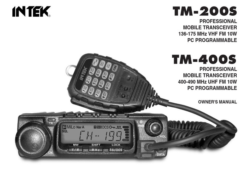
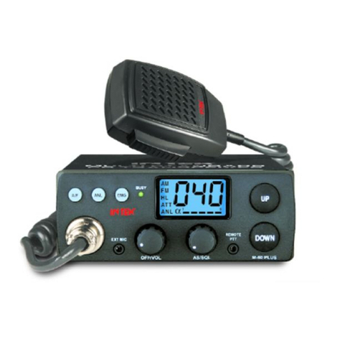
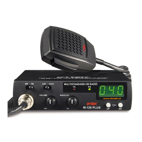
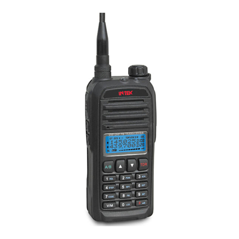
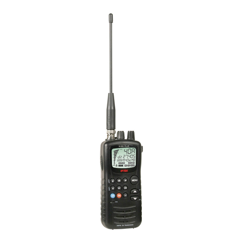
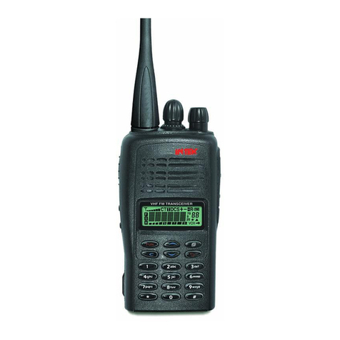
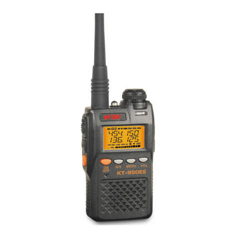
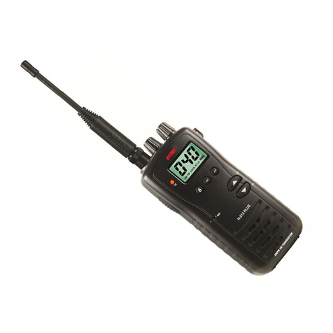
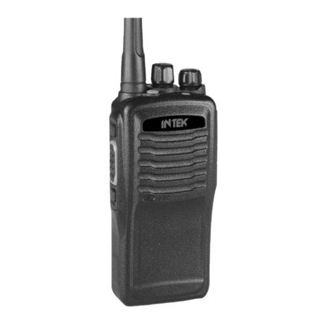
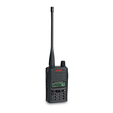
Intek KT-355EE User manual

KT-355Ek
‘:
VHF FM HANDHELD’TRANSCEIVER
1
RICETRASMETTITORE VHF FM
1
PORTATILE
!
IINSTRUCTION
MANUAL
MANUALE
DI
ISTRUZIONI
(versione lingua inglese)


Before
USing
fhe
Unit
(Observe the Following Precautions)
n Never
tauch
the unit’s cores or
trimmers
They are already adjusted
for
Optimum
Performance
The unit will not operate
on a 24 V power
suPPlY-
n The unit’s operatlng
voltage range
1s
6 0
. 160V
Never connect the
unit to an extemal
power supply
out-
side of this range
Doing
so
could
Cause
-
16V
unit
Batteries
H
Make sure the
j
+
;
and
/
)
ends of the battertes are ori-
ented correc!ly
n Never
use
new and
old
batteries together
9
Never expose
old
batteries to an open flame
Suitable batteries
n SUM-3 magnestum batterles
H
AlkalIne batteries
E
Nickel-cadmium batterles
(Same
types are not compatible
1
2

Setup
7
Attaching the antenna
2 Battery insertion .

3 Switching power on and
1
adjusting the volume
/
‘,
1’
Turn the volume knob
clockwlse’
Turn the volume knob
further
Tuntöl
it
cllcks
to
swltch
power
on,
clockwse
to
~ncrease
the volume
4
Squelch
adjustment
, n How to
eliminate
background
‘Turn the
squelch
knob
clockwlse
iunt~l background
hiss
1s
no
longerl
,audible
I
Stop
turning
the knob as
soo”
as
background
hiss
IS
inaudible
m
It may be difhcult
to
recerve
weak sfgnals ff the squelch
knob is turned too far
clockwfse
4

5
Settinn
the frequencv
n There are three
ways
to
set the frequency
setting
while
the
new
one
IS
bein
e
numeric
keys uency
keys
Setting the frequency
to
145.06 MHz
1) Press the
151
key
to
Input the 1 MHz column
SAVE
a-j
u
111’5.;
-
!
Flashes
2) Press
the
[0] key
to
Input the 100 kHz
colum”
SET/%
a-i
1
:95.E?
j
Y
FI%hEZ
3) Press the
[6]
key
to
Input the 10 kHz column
When settlng is
compiete.
a
lang high pltched
beep (peep) Sounds
Turmng the rotary channel selector
causes
the frequency
to
rise
or
fall
m
tuning steps
of the
preset
size
See page 46 for an explanat~on of tumng
Steps
Frequency r!ses Frequency falls
Rotary channel selector
Turnlng the rotary channel selector
wth
the FUNC key held down
causes
the fre-
quency
to
rise
or
fall
I”
100 kHz tumng
Steps
Press the
A
key
to
rase
the frequency
setting and the
V
key to
lower
It
The
amount the frequency settlng changes
wth
each press depends on the tuning
step
sett1ng
5

6
Transmitting
. After setting the frequency and making sure that no
other statlons are broadcastlng
on
It.
press the PTT
switch
to transmIt
.
H
A wide range of accessorles
1s
avatlable to enable
you
to enjoy the unit
an
many different ways.
nducafor
hghts
during
een
Indicator
Itghts
g
recelve
Status
6

Functions
and
ODeration
1.
Terminology
3
1
VFO mode
In the VFO mode the frequency settlng
IS
displayed and the
M, C and DUAL Indlcations are not displayed
The VFO mode
IS
actlve when the
untt
1s
flrst turned on
(the factory
setting)
Vorurne
knob
2 Memory mode
In the memory mode the frequency settlng and the memory
address number are displayed.
In the VFO mode, press the
B
VIM ENT key
to
swltch to the
memory mode. (See pages 29-33 )
5
Memory
(M)
Me’mory
address number
6
Paging mode
Cal1
mode
In the
cal1
mode the C indication
IS
displayed
(See page 40
)
Carl
IrequUlcy
@*pqyq
Set mode
In the set mode the SE Indlcatlon
IS
displayed
(See pages
10
and 48-50
.)
Set
mode
Extra mode
In the extra mode the EA Indlcatlon
IS
dlsplayed
(See pages 54-55
)
Set mode
In the paglng mode the PAG Indication
1s
displayed
(See pages 21-26
.)
7

2.
1)
basic
functions
Functions accessed by pushlng keys
directly
l-3
QY
Function
O-Q
1
Numeric
Input 15
1
LAMP 01splay
illumination
ONIOFF
l
-
1
SQL OFF Squelch
control
ONIOFF
-
VIM
VFOimemory
mode toggle
31
v
Frequency or address number down,
5
/
A
(
Frequency
or
address
#
CL PS Cancel mode
-
1
MS Memory scan ON/OFF
(
36
l
CALL
Cal1
up
ca11
frequency
,
401
2) Functions accessed by holding down the FUNC key
and pressing another key
.x F
+
means
“wth
the FUNC key held down
”
(See pages 45-47
)
Functions printed
it.
hght
blue
I
F
*
PO
F +DUAL
/
Dua,
,,,,,:L-
-=
Switch
tral-ismt
power
level
F
+
SFT Memory shltt mode ONIOFF
33
F + STEP
I
Tuning step settlng 146
_--M-
F
+
SAVE
Save
ONfOFF
l
F+F L Frequency leck ON/OFF 47
F
+
T SQIDM
1
Tone
squelchitone
encoder
toggle
)
28
)
F
+
REV,HSC cies
,n
repeater
mode
~-.
Ft
L LAMP
F
+
PAG
i
Paging,code squelch ONIOFF
F+MS
M
F
+
PS
i
Scan
ONIOFF-
I
35
F +
C&LL>
P L PTT
swtch
leck ON OFF 47
~F+ DTMF M
I
DTMF
memory
mode
’
43
i
~~
1-

3) Functions accessed by
presslng
numeric
keys in the
set mode.
The following functions are accessed by switching
to
the
set mode and presslng the keys Indlcated
(See pages 48-50
)
z
SE
+
means “press the following key while
an
the set
mode
”
n
While
holding down the FUNC key. press the 0
SET/%
key
The frequency
Indicatton
dlsappears from the display
The [SE] (SET MODE) indication
IS
displayed. showing that
the set mode
1s
actlve
K~Y
, v-Y*
SE
+
0
Beep
ONIOFF
1
48
SE
+
1
Leil
gth
of
paglng
beep
li5 toggle
l
48
1
cc
1
/
1 kHz
column
input
from
nuneric
YL
-
L
: keys
enableidisable
toggle
48
j
SE
+
3
Repeater
+
PAG
transmissmn
delay
time
49
SE -4
Squelch
pop
no~se
reductlon 49
SE
+
5
APO (Auto Power Off) ONIOFF 49
SE
-
6
Enabie
encoder
even
,n
frequency
leck
status 50
SE
+7
CTCSS
frequencv
settIna
mode
(CTN160
tone
frequency-selectlon)
.n
IY
SE
+
8
1
Repeater offset frequency
settlng
/
19
SE
+
9
(Display
mdlcations
appear
normally.
but
no
tones
are
produced
Internally
)
4) Functions accessed in the set mode by holding
down the FUNC key and pressing another key.
(See pages 51-53
.)
SETISB
0. 1. 3
-
9
EJ
keys
~+~+~+Qq
\
/
Set mode
channel
sele lurned
wlth
th
Id down
between
100
9

5).
Functions
accessed by pressing keys in the extra
mode
s
EA
+
means
“press the following key
whlle
in the extra
mode.”
(See pages 54-55
.)
Set mode
i
Extra mode
Numeric key
R
Select mterval for save
functlon
Reduce DTMF transmlsslon
Speed
Gong
medium
pltched
beep
(boo)
(no
functlon)
Long medlum
pitched
beep
(boo)
(no
functlon)
Enable
frequency Input from 100 MHz
column
Long medium
pitched
beep
(boo)
(no
tunctmn)
Lang
medlum
pltched
beep
(boo)
(no
functlon)
10

Operation and Functions of Parts
Top View
Be”
c’ip
I
Waterproolcap
.I
MIC
(extemal
microphone jack)
Jack for connectlng an Optional
mlcrophone-speaker
1
//
combmatlon
(CMP111 or CMP115). headset
wth
PTT
swltch
(CHPlll)
or
tlepm mtcrophone (CMP113)
SP
(extemal
speaker
jack)
Jack for connectmg an
optional
rmcrophone-
speaker
comblnatlon
(CMP111
or
CMP115)
or
headset with PTT
swtch
(CHPlll)
This
jack
allows
connectlon
of an
extemal
speaker
or
earphone
wth
a
Load
impedance
of
8
ohms
No
wund
6s”es
from the
“nlt’s
mternal
speaket
when aplug
IS
inserted
into this ]ack
VOLUME (power
switch/volume
knob)
Turn this knob
to
adlust the
volume
Alwa
squelch off by holdlng down the SQL OFF
turning the SQL knob all the
way
counterc
before adfustmg the
volume
SQL (squelch knob)
CHANNEL
(rotary
channel
selector
knob)
Thls knob
IS
used
to
Change
the
transmrt/recewe
frequency It
IS
also used
to
Change
the tone
frequency, tunmg
Step
size
and
memory
address
number
Turn
clockwse
to
~ncrease, and
counterciockwse
to
reduce, the frequency settlng
The
mitial
tunmg step settlng
IS
10 kHz The tunmg
step setbng
tan
be changed
11
deslred
to
5. 12 5.
20. 25. 50, 75
or
100
kHz,
for
a
total of
eight
set-
t1ngs
(7)
Adpsf
fhis hnob
to
ellmmate
audlble
h1.w
durmg
scan
dual
watch.
SBYB,
pag,ng
or
Code
squelch
operafron.
(2)
Tune
IO
an
unused
channei
before
ad/usfmg
fhe
squelch
CALL/P.L
(cal1
buiton)
This button
IS
used for
prlortty
call-up of the
cal1
frequency
Presslng It while the FUNC button
IS
held down
toggles the PTT leck functlon on and off
11

Front View
FUNCTION (function)
A
vamty
of
special
functlons ca” be
accessed by holding down this key and
press,ng another key 1
PTT switch
Swtches
between
transmlttlng
and
recelwng
SQL OFF (squelch oll button)
Squelch
IS
dlsabled for as lang
as
this button is held
down,
regardless
of the sett,ng of the squelch knob
lt has the same effect as turning the squelch knob all
the way
counterclockwise
Presslng the SQL OFF button while the PTT
switch
is
held down causes
a
DTMF
signal
to
be
transmltted
Front control Panel
(keys)
2 DUAL
A LAMP L.LMP
SQL
0FFIDTMF.M
_
DC IN
(extemal
power supply connector jack)
Plug
the lopt~onal) power supply
Cord
~nto
thls
jack
The umt swltches automat~cally fram the battery
pack
to
the extern.3 power supply when the
plug
is
‘nserted
m
Center
pl”
is
negative
Aiways
turn :he power
swltch
off
before
unpiugging
he
power supply cable Jhe
unit
s
operaling
Vollage
range
:.5
6
0
, 16
0
V
Neer
connect
11
10
an
exlernai
power supply
oufside
of Ibis
range
CALL1P.L
3 SFT
D
A
CODE
C
V
PAG
6
F.L
B
V/M ENT
0 SETISB

Memory scan memory address nurnber rndication
Paglng
funct~on
decode mark rndrcation
Protect mode
jmemory
writeloverwrlte
prohtbrted
Memory
cal1
tm~k~i_,,,,,1~~
Shift frequency
+/-
direction
rndicatton
Code address number mdrcatron
l--
L
SE Set mode Indrcatron
CH Tuning
Step
settrng rndrcatron
OF Offset frequency sethng rndrcatron
EA Extra mode rndicatron
IF
Internal tone frequency settrng
indication
CF CTCSS tone frequency setttng rndication
%Flequires optronal CTCSS unit
SA Save
~nterval
settrng rndrcatron
CP Individual code address rndrcatron
C Code settrng mode indrcatron
CO
-
C6
+ CP Code address rndrcatron
il
-
u
:
DTMF memory block rndrcation
Code squelch
operahon
rndrcatron
l
L
Dual
watch
Operation
mdication
UHF band
irequency
display
(VHF
ior
C166)
Tome
encoder
operahon
rndrcahon
Tone squelch operatron rndrcatron
Auto power off
indicatron
PTT leck indication
Frequency leck indication
1 kHz/100 Hz column indrcatron
Busy scan
operabon
rndrcatron
Save
operatron
mdrcatron
1 kHz
level
Input enabled
Signal strength
meter
during receptron
Transmlssron output level meter during fransmss~on
100 MHz
level
rnput
enabled
Drsplayed when all reset enabled
(When drsplayed reset
rs
powble
)
Lower
power transmrssron output rndication
Mrddle power transmrssron output mdrcahon
High power
transmission
output rndrcatron
‘-
Battery rndrcator
(Flashes when batterres
arc
low
)
13

n On
thts
and the pages
which
follow, the functions of
each
key are descrrbed
rn
the foilowtng
Order
1) Key pressed drrectly
Function
printed
I”
~vory
2) Key pressed
wrth
FUNC key held down
Function prlnted
,n
3) Key pressed
rn
set mode
SET/SB
Other key
m+@*q
4) Key pressed
tn
set mode with FUNC key held down
J-
(except for 0
SETISB)
r
w
5) Key pressed
fn
extra mode
:
-
6)
Numeric,
A.
B,
C.
D.
Jt-
or
#key pressed
wth
PTT
swdch
held
down
1PO
+
1) Inputs the numeral 1
-
2) Swttches transmrssron output
+
3) Sets length of pagtng beep
(one or five
trmes.)
--.
4) All reset.
(restores factory settmgs
)
4
5)
High
Speed
scan
on/off
-.-.+
6) Transmtts DTMF
Signal
1
14

Beep indications
When you press the control buttons of the
unit,
beeps
inform you of the
Status
of the Operation being performed
The
pftch
and durahon of the beeps dlffers as descrlbed
below
Pip
Operation
button pressed
regtstered
correctly
Peep
\
(Lang high
pltched
beep)
Operation
successfully completed.
(Exampk
Frequency
successfully
entered
In
memory
)
/
.
Boo
(Lang
medlum
pltched
beep)
Operation button pressed
not
reglstered
correctly
or
mvalld
button pressed.
/
Pip-pip-pip-pip
lhpeated
high
pltched beeps,
!
Indlcates auto power otf
operation
or
a
transmtswx
recelved
an
the paging mode
Pilala-pilala-pilala
Transmission sent
an
the paglng mode
/
\
Puff
\
Wort
lOW
pltched
beep,
Functlon
canceled
or
mtial
settmgs
reatored
I
15

Repea ter Operation
n About repeater Operation
n Conventional Operation
This
term refers to radle communication
via
a ‘repeater
statlon”
(a relay Statton)
Since
a repeater Station IS
requlred,
the repeater function
IS
generally only used to
communxate
wth
locations
too
far away to communicate
wth
dlrectly
Transmittang
and receiving
via
the repeater
statlon
takes
place on different
frequencles
(The sending frequency IS 600 KHz (VHF),
lower
than the
receiving frequency
)
This
unit automatically sets the
sending
frequency GOOKHz
(VHF). lower than the receiving frequency when the
repeater functlon is
turned
on.
(TX
RX 145 240 MHz) (TX RX
145
240
MHz)
n
Repeater Operation
Repeater station
(Tx
145
‘O” MHz
RX 1451800 MHz
TX 145 800 MHz
RX 145 200
MHz
16

Repeater Operation
Canceling the repeater
function
Set the frequency to
match
that of the repeater
Station
1)
Hold down the FUNC key and press the 6 RPT key
When you press the PTT
swrtch
the
Signal
IS
transmrtted
at a frequency -600 KHz lower than the frequency shown
on the drsplay
(+600KHz
offset).
(To transmit with a
600
KHz offset, hold down the FUNC
key and press the 8 RPT key
agarn.)
2)
3)
While transmitting, press
CALL/P.L
key to access the
repeater Station. (The 1.750 KHz burst Signal is
trans-
mitted only while the
CALL/P.L
key is depressed.)
Hold down the FUNC key and press the 8 RPT key.
A [
-1
appears on the display. indicating -600
KHZ
offset
Status.
Hold down the FUNC key and press the
6
RPT key once
again. A [ +
]
appears on the display, indicating
dO0
KHz offset
Status.
Hold down the FUNC key and press the 8 RPT key a
third
ttme.
The
[
+
]
indication disappears from the dis-
play and the repeater mode is canceled.
17

Reversing the repeater sendlreceive
frequencies
n
Thrs
function allows you to communrcate drrectly
wrth
another
Station
(wrthout using the repeater
Station)
It
IS
called reverse (REV) operahon.
1) Hold down the FUNC key and press the 9
REV/HSC
key
The [
-
]
or
[
+
]
rndrcatron
on the drsplay flashes on and
off to
rndrcate
that the sendrng and recervrng frequen-
cies have been reversed
2) To cancel
thrs
functron,
hold down the FUNC key and
press the 9
REVIHSC
key
agarn
(1)
If.
after step 1) above
IS
performed. you succeed
rn
commu-
nrcatrng
wrth
the other
Station.
you may be able to
contmue
to communrcate wrthout
usrng
the repeater functton at all
If drrect contact has been establrshed. try
communrcatrng
wrthout
usrng
the repeater funchon
(srmplex
Operation)
(2)
Usrng
srmplex Operation means that more other
People
tan
use the repeater
statron
It is therefore desrrable to use
srmplex operatron whenever
possrble
(as a courtesy to
other users of the repeater
Station)

Setting the CTCSS tone frequency
n
Thrs
functron
IS
avarlable
rf
the optional CTCSS unit
(tone
squelch) has been
rnstalled.
There are 38 tone
squelch frequencres to
choose
from.
-
1)
Swatch
to the set mode.
2) Press the 7
T.SQ/DM
key.
The current CTCSS tone frequency settrng appears on
the drsplay.
The CF
tndrcatron
also appears. showrng that the
unrt
IS
tn
the CTCSS tone frequency sethng mode.
(CF
Stands
for CTCSS FREQUENCY
)
3) Select the tone frequency of your
chorce
usrng
the
V
/A
keys or the rotary channel selector
During
frequency setttng. a puff (short low
prtched
beep)
Sounds
at 88.5 Hz.
4) After settrng the desired frequency. press the #CL PS
W
Changing the offset frequency
n The factory settrng for the offset frequency
IS
600 KHz.
Follow the procedure below to set a new offset frequency
1)
Swatch
to the set mode
2) Press the 8 RPT key
The current offset frequency settrng appears on the dis-
play The [OF]
tndrcatron
also appears.
showrng
that the
unrt
IS
In
the offset frequency settrng mode
(OF Stands for OFFSET FREQUENCY )
3) Set the new offset freduency
usrng
the 0
-
9 keys, the
A
iV
keys. or the rotary channel selector
4) After setting the desrred frequency. press the # CL PS
key
19
Table of contents
Other Intek Transceiver manuals

Intek
Intek MT-5050 User manual

Intek
Intek seatec-5 User manual

Intek
Intek HR-200S User manual

Intek
Intek KT-370EE User manual

Intek
Intek KT-380EE User manual

Intek
Intek M-130 PLUS User manual

Intek
Intek H-520 PLUS User manual

Intek
Intek M-130 PLUS User manual

Intek
Intek M-899 VOX User manual

Intek
Intek H-510 PLUS User manual

Intek
Intek MT-174W10 User manual

Intek
Intek DRS-5070 User manual

Intek
Intek KT-980HP User manual

Intek
Intek T100WP User manual

Intek
Intek M-60 Plus User manual

Intek
Intek MT-4040 User manual

Intek
Intek M-799 PLUS User manual

Intek
Intek MT-3030 User manual
Intek
Intek M-550 Power User manual
Intek
Intek M-100 PLUS User manual