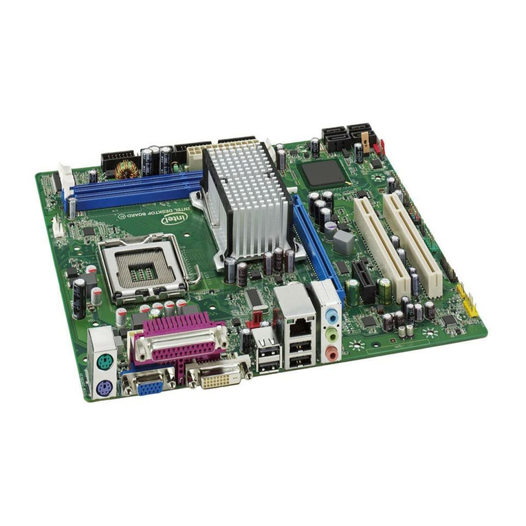
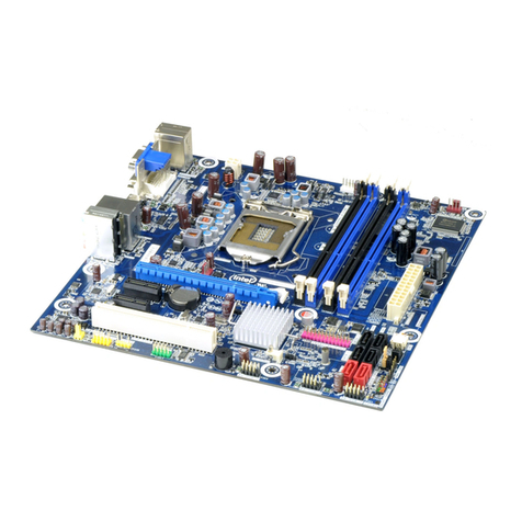
Intel AL440LX User manual

AL440LX
Motherboard
Product Guide
Order Number: 680701-001

Revision History
Revision Revision History Date
-001 First release of the AL440LX Motherboard Product Guide. July 1997
Intel Corporation (Intel) makes no warranty of any kind with regard to this material, including, but not limited
to, the implied warranties of merchantability and fitness for a particular purpose. Intel assumes no
responsibility for any errors that may appear in this document. Intel makes no commitment to update nor to
keep current the information contained in this document. No part of this document may be copied or
reproduced in any form or by any means without prior written consent of Intel.
†Third-party brands and names are the property of their respective owners.
Copyright Intel Corporation, 1997. All Rights Reserved.

iii
Contents
1 Product Description
Features................................................................................................................................7
Components..........................................................................................................................8
Back Panel I/O Connectors...................................................................................................9
2 Installing the Motherboard
Before You Begin................................................................................................................11
Installing a Processor..........................................................................................................12
Installing the Retention Mechanism............................................................................12
Installing the Processor..............................................................................................13
Setting the Processor Speed......................................................................................14
Upgrading to a Boxed Pentium®II Processor.....................................................................14
Removing the Installed Processor..............................................................................15
Removing the Heatsink Support Base........................................................................16
Upgrading the Processor............................................................................................18
Installing Memory................................................................................................................19
Removing Memory..............................................................................................................20
Replacing the Battery..........................................................................................................21
Installing and Removing the Motherboard ..........................................................................23
3 Configuring the Motherboard
Before You Begin................................................................................................................25
Configuration Modes...........................................................................................................26
Setting the Processor Speed..............................................................................................27
Clearing the Passwords......................................................................................................28
4 Using the Setup Program
Setup Menus.......................................................................................................................29
Function Keys.....................................................................................................................30
Maintenance Menu .............................................................................................................30
Main Menu..........................................................................................................................31
Floppy Options Submenu...........................................................................................32
IDE Device Configuration Submenus.........................................................................33
Advanced Menu..................................................................................................................34
Resource Configuration Submenu .............................................................................35
Peripheral Configuration Submenu ............................................................................36
Keyboard Features Submenu ....................................................................................37
Video Configuration Submenu ...................................................................................37
DMI Event Logging Submenu ....................................................................................37
Security Menu.....................................................................................................................38
Power Menu........................................................................................................................38
Boot Menu ..........................................................................................................................39
Hard Drive Submenu..................................................................................................40
Removable Devices Submenu...................................................................................40
Exit Menu............................................................................................................................40

Contents
iv
5 Upgrading the BIOS
Preparing for the Upgrade ..................................................................................................41
Obtaining the Upgrade Utility .....................................................................................41
Recording the Current BIOS Settings.........................................................................41
Creating a Bootable Floppy Diskette..........................................................................42
Creating the BIOS Upgrade Floppy Diskette..............................................................42
Upgrading the BIOS............................................................................................................42
Recovering the BIOS..........................................................................................................43
Changing the BIOS Language............................................................................................44
6 Technical Reference
Motherboard Connectors ....................................................................................................45
Front Panel Connectors......................................................................................................48
Motherboard Resources......................................................................................................49
Memory Map ..............................................................................................................49
DMA Channels...........................................................................................................49
I/O Map .....................................................................................................................50
PCI Configuration Space Map....................................................................................52
Interrupts....................................................................................................................52
A Error Messages
BIOS Beep Codes...............................................................................................................53
BIOS Error Messages.........................................................................................................53
B Regulatory and Integration Information
Regulatory Requirements ...................................................................................................55
Safety Standards........................................................................................................55
Electromagnetic Compatibility (EMC) Regulations.....................................................56
Product Certification Markings....................................................................................56
Installation Precautions.......................................................................................................57
Installation Instructions .......................................................................................................57
Ensure Electromagnetic Compatibility (EMC).............................................................58
Ensure Host Computer and Accessory Module Certifications....................................58
Prevent Power Supply Overload ................................................................................59
Place Battery Marking on the Computer.....................................................................59
Use Only for Intended Applications............................................................................59

AL440LX Motherboard Product Guide
v
Figures
1. Motherboard Components............................................................................................8
2. Back Panel I/O Connectors..........................................................................................9
3. Installing the Processor Retention Mechanism ..........................................................12
4. Installing the Processor..............................................................................................13
5. Installing the Heatsink Support Top Bar.....................................................................14
6. Removing the Heatsink Support Top Bar and the Processor.....................................15
7. Removing the Heatsink Support Retention Pins ........................................................16
8. Placing the Heatsink Support Base Removal Tool on the Retention Pins..................17
9. Using the Heatsink Support Base Removal Tool .......................................................18
10. Location of DIMM Sockets .........................................................................................19
11. Installing a DIMM........................................................................................................20
12. Replacing the Battery.................................................................................................22
13. Mounting Screw Holes ...............................................................................................23
14. Configuration Header.................................................................................................26
15. Motherboard Connectors............................................................................................45
Tables
1. Jumper Settings for the Setup Program.....................................................................27
2. Setup Menu Bar.........................................................................................................29
3. Setup Function Keys..................................................................................................30
4. Maintenance Menu.....................................................................................................30
5. Main Menu .................................................................................................................31
6. Floppy Options Submenu...........................................................................................32
7. IDE Device Configuration Submenus.........................................................................33
8. Advanced Menu.........................................................................................................34
9. Resource Configuration Submenu.............................................................................35
10. Peripheral Configuration Submenu............................................................................36
11. Keyboard Features Submenu ....................................................................................37
12. Video Configuration Submenu ...................................................................................37
13. DMI Event Logging Submenu ....................................................................................37
14. Security Menu............................................................................................................38
15. Power Menu...............................................................................................................38
16. Boot Menu..................................................................................................................39
17. Hard Drive Submenu..................................................................................................40
18. Removable Devices Submenu...................................................................................40
19. Exit Menu...................................................................................................................40
20. Chassis Security Header (J2B1) ................................................................................45
21. Wake on LAN Header (J1C1).....................................................................................46
22. ATAPI CD Audio Connector (J1F1)............................................................................46
23. ATAPI Telephony Connector (J2F1) ..........................................................................46
24. ATAPI Line In Connector (J2F2)................................................................................46
25. Fan 1 Header (J8M1).................................................................................................46
26. Fan 2 Header (J3F1)..................................................................................................47
27. Fan 3 Header (J5L1) (Active Heatsink Fan)...............................................................47
28. SCSI Hard Drive LED Input Header (J8B1)................................................................47
29. Wake on Ring Header (J8A1) ....................................................................................47
Contents
vi
30. Front Panel Connectors .............................................................................................48
31. Memory Map ..............................................................................................................49
32. DMA Channels...........................................................................................................49
33. I/O Map ......................................................................................................................50
34. PCI Configuration Space Map....................................................................................52
35. Interrupts....................................................................................................................52
36. Beep Codes ...............................................................................................................53
37. BIOS Error Messages ................................................................................................53

7
1 Product Description
This chapter gives an overview of the AL440LX motherboard, including:
• Features
• Components
• Back panel I/O connectors
Features
The motherboard has these features:
• Support for one 233, 266, or 300 MHz Intel Pentium®II processor with a 512 KB second-level
cache integrated in the Single Edge Contact (S.E.C.) cartridge
• Support for up to 384 MB of 66 MHz synchronous DRAM (SDRAM) using three DIMM
sockets with 168-pin DIMM modules and 3.3 V memory
• Intel 440LX AGPset that includes a high-speed processor interface controller, a DRAM
controller, the Accelerated Graphics Port (A.G.P.) interface, a Universal Serial Bus (USB)
controller, a fully synchronous PCI bus interface, the real-time clock, and support for power
management and system management mode
• National Semiconductor PC97307 I/O component that includes the floppy-drive interface, one
multimode parallel port, two FIFO serial ports, keyboard and mouse controller, and an IrDA†-
compatible interface
• Intel/Phoenix BIOS that supports power management, Plug and Play, advanced IDE features,
and password security
• Five expansion slots: one 16-bit ISA/AT†-compatible slot, three PCI-compatible expansion
slots, and one combination slot for either a PCI or an ISA card
• Two USB connectors
• Onboard connector that supports add-in A.G.P. boards
• Optional onboard audio subsystem based on the Yamaha OPL†family of single-chip audio
controllers (YM 715)
• Optional onboard Yamaha YM 704 wavetable synthesizer
• Optional hardware monitor that integrates a temperature sensor, fan speed sensors, power
supply voltage monitor, support for Intel LANDeskClient Manager, and support for chassis
security
✏NOTE
Information about Intel motherboards including technical product specifications, BIOS upgrades,
and device drivers is available under “Product Info” at the Intel World Wide Web site:
http://www.intel.com/

Product Description
8
Components
Figure 1 shows the components on the motherboard.
OM06239
BCDFEGA
H
K
J
I
L
MONSR P
T
U
W
V
Q
Figure 1. Motherboard Components
A Optional chassis security header M Floppy drive connector
B Optional Wake on LAN†header N IDE connectors
C Battery O Front panel header
D Optional Line In connector P Accelerated Graphics Port (A.G.P.) connector
E Optional CD-ROM audio connector Q Configuration header
F Optional telephony connector R Optional SCSI hard disk LED header
G Back-panel I/O connectors S Wake on Ring header
H Slot 1 connector T Speaker
I Fan 3 header (for the active heatsink fan) U Fan 2 header
J DIMM sockets V PCI connectors
K Primary power connector W ISA connectors
L Fan 1 header
✏NOTE
Components labeled optional do not come on all AL440LX motherboards.

AL440LX Motherboard Product Guide
9
Back Panel I/O Connectors
Figure 2 shows the back panel connectors on the motherboard.
OM06235
DF
C
H
J
A
G
I
B
E
Figure 2. Back Panel I/O Connectors
A PS/2†connector (mouse or keyboard) F Serial port 1 connector
B Parallel port connector G Serial port 2 connector
C MIDI/game port connector (optional) H Audio Line Out jack (optional)
D PS/2 connector (mouse or keyboard) I Audio Line In jack (optional)
E USB connectors J Audio Mic In jack (optional)

Product Description
10

11
2 Installing the Motherboard
This chapter describes the following:
• Installing a processor
• Preparing the motherboard for installing a boxed Pentium II processor
• Installing and removing memory
• Replacing the battery
• Installing and removing the motherboard
Before You Begin
CAUTION
Before you install this motherboard in a chassis, see Appendix Bfor regulatory requirements and
precautions.
• Always follow the steps in each procedure in the correct order.
• Set up a log to record information about your computer, such as model, serial numbers,
installed options, and configuration information.
• Use an antistatic wrist strap and a conductive foam pad when working on the motherboard.
WARNINGS
The procedures in this chapter assume familiarity with the general terminology associated with
personal computers and with the safety practices and regulatory compliance required for using
and modifying electronic equipment.
Disconnect the computer from its power source and from any telecommunications links,
networks, or modems before performing any of the procedures described in this chapter.
Failure to disconnect power, telecommunications links, networks, or modems before you open
the computer or perform any procedures can result in personal injury or equipment damage.
Some circuitry on the motherboard can continue to operate even though the front panel power
button is off.
CAUTION
Electrostatic discharge (ESD) can damage components. Perform the procedures described in this
chapter only at an ESD workstation. If such a station is not available, you can provide some ESD
protection by wearing an antistatic wrist strap and attaching it to a metal part of the computer
chassis.

Installing the Motherboard
12
Installing a Processor
To install a processor, you must:
1. Install the retention mechanism.
2. Install the processor.
3. Set the processor speed.
Detailed instructions for each of these procedures follow.
✏NOTE
If you are installing a boxed Intel Pentium II processor, see the instructions on page 14.
Installing the Retention Mechanism
✏NOTE
To install the retention mechanism, you need a Phillips (#2 bit) manual torque screwdriver
capable of a 6.0 in.-lb.
±
1.0 in.-lb. (0.678 N-m
±
0.113 N-m) setting. The screwdriver also must
have a shaft longer than 2 inches.
To install the retention mechanism, follow these steps:
1. Observe the precautions in “Before You Begin” (see page 11).
2. Locate Slot 1 (A in Figure 3) and the four attachment studs (B) on the motherboard.
OM06225
E
D
B
C
A
Figure 3. Installing the Processor Retention Mechanism
3. To position the mechanism (C), orient it as shown in Figure 3. The tab (D) on the connector
fits into a notch in the base of the mechanism. When properly seated, the base of the
mechanism is flush with the motherboard.

AL440LX Motherboard Product Guide
13
CAUTION
Overtightening the captive nuts on the retention mechanism can damage the motherboard. Tighten
the captive nuts (E in Figure 3) to no more than 6.0 in.-lb.
±
1.0 in.-lb. (0.678 N-m
±
0.113 N-m).
4. Finger tighten all four captive nuts to make sure they start correctly on the threads of the
attachment studs.
5. To secure the mechanism, tighten the captive nuts with the torque screwdriver to no more than
6.0 in.-lb. ±1.0 in.-lb. (0.678 N-m ±0.113 N-m).
Installing the Processor
To install the processor, follow these steps:
1. Insert the processor in the retention mechanism (A in Figure 4).
2. Press down on the processor until it is firmly seated in the Slot 1 connector and the latches (B)
on the processor lock into place.
OM06228
A
B
B
Figure 4. Installing the Processor

Installing the Motherboard
14
3. Slide the top heatsink support bar (A) onto the retaining pins (B) of the support’s base as
shown in Figure 5.
OM06229
B
A
Figure 5. Installing the Heatsink Support Top Bar
Setting the Processor Speed
After you install the processor and install the motherboard, set the processor speed by using the
Setup program. See Chapter 3 to set processor speed.
Upgrading to a Boxed Pentium®II Processor
Use the instructions in this section to prepare the motherboard for a boxed Pentium II processor
upgrade.
To prepare for a boxed Pentium II processor upgrade, you must:
1. Remove the heatsink support top bar and the installed processor.
2. Remove the heatsink support base.
3. Upgrade the processor.
Detailed instructions for each of these procedures follow.

AL440LX Motherboard Product Guide
15
Removing the Installed Processor
To remove the installed processor, follow these steps:
1. Observe the precautions in “Before You Begin” (see page 11).
2. Turn off all peripheral devices connected to the computer. Turn off the computer.
3. Remove the computer cover.
4. Remove the motherboard from the computer chassis. Refer to “ Installing and Removing the
Motherboard” on page 23.
5. Place the motherboard on a flat work surface and remove any components that block access to
the installed processor.
6. Remove the top bar of the heatsink support from the base as shown in Figure 6. Press in on the
latches (A) to release the top bar.
OM06230
B
B
A
Figure 6. Removing the Heatsink Support Top Bar and the Processor
CAUTION
Pressing on the motherboard or components while removing the processor can cause damage. If
necessary, you can safely press on the motherboard’s plastic connectors to gain leverage while
removing the processor.
7. Remove the processor by pressing in on the latches (B) and pulling the processor straight up as
shown in Figure 6. Place the processor aside.

Installing the Motherboard
16
Removing the Heatsink Support Base
✏NOTE
To remove the heatsink support base from the motherboard, you need a special removal tool
(MID #58982) that is available from Dexter Design (call 503-648-7000 for ordering information).
To remove the heatsink support base follow these steps:
1. With your fingers, remove the two retention pins (A) from the heatsink support base (B) as
shown in Figure 7.
OM06231
A
B
A
Figure 7. Removing the Heatsink Support Retention Pins

AL440LX Motherboard Product Guide
17
2. Place the heatsink support removal tool (A) over the two outside posts of the heatsink support
base (B) as shown in Figure 8. Make sure the tool completely engages the posts.
OM06232
B
A
Figure 8. Placing the Heatsink Support Base Removal Tool on the Retention Pins

Installing the Motherboard
18
3. Carefully rock the tool back and forth until the heatsink support base disengages from the holes
in the motherboard (Figure 9). There is an audible click when the base disengages from the
motherboard.
OM06233
Figure 9. Using the Heatsink Support Base Removal Tool
4. Remove the tool and the heatsink support base from the motherboard.
Upgrading the Processor
Refer to the boxed Intel Pentium II processor documentation for installation instructions.

AL440LX Motherboard Product Guide
19
Installing Memory
You can install from 8 MB to 384 MB of memory in the motherboard DIMM sockets. The board
has DIMM sockets arranged as banks 0, 1, and 2. The motherboard supports the following
memory features:
• 168-pin 3.3 V DIMMs with gold-plated contacts
• 66 MHz unbuffered SDRAM
• Non-ECC (64-bit) or ECC (72-bit) memory
• 8 MB, 16 MB, 32 MB, 64 MB, and 128 MB modules
When adding memory, follow these guidelines:
• You can install DIMMs in any of the three banks.
• You can use different size DIMMs in different banks.
• The BIOS detects the size and type of installed memory.
• For ECC operation to be available, all installed memory must be ECC and you must enable the
ECC Configuration feature in the Setup program (see page 34).
✏NOTE
DIMMs must meet the Intel specifications for either 64-bit or 72-bit SDRAM. For information
about vendors that support these specifications refer to the Intel World Wide Web site:
http://www.intel.com/
Figure 10 shows the location of the DIMM sockets.
0
1
2
Figure 10. Location of DIMM Sockets
To install DIMMs, follow these steps:
1. Observe the precautions in “Before You Begin” (see page 11).
2. Turn off all peripheral devices connected to the computer. Turn off the computer.
3. Remove the computer cover and locate the DIMM sockets.
4. Holding the DIMM by the edges, remove it from its antistatic package.
5. Make sure the clips at either end of the socket are pushed away from the socket.

Installing the Motherboard
20
6. Position the DIMM above the socket. Align the two small notches in the bottom edge of the
DIMM with the keys in the socket.
7. Insert the bottom edge of the DIMM into the socket.
8. When the DIMM is seated, push down on the top edge of the DIMM until the retaining clips at
the ends of the socket snap into place. Make sure the clips are firmly in place.
9. Replace the computer cover.
10. If you installed a DIMM with ECC memory, start the computer and use the ECC Configuration
feature in Setup to enable the use of ECC.
OM06224
Figure 11. Installing a DIMM
Removing Memory
To remove a DIMM, follow these steps:
1. Observe the precautions in "Before You Begin" (see page 11).
2. Turn off all peripheral devices connected to the computer. Turn off the computer.
3. Remove the computer cover.
4. Gently spread the retaining clips at each end of the socket. The DIMM pops out of the socket.
5. Hold the DIMM by the edges, lift it away from the socket, and store it in an antistatic package.
6. Reinstall and reconnect any parts you removed or disconnected to reach the DIMM sockets.
Table of contents
Other Intel Motherboard manuals

Intel
Intel DG965MQ User manual

Intel
Intel DP965LT User manual

Intel
Intel D945PLRN User manual

Intel
Intel S1200BTL User manual

Intel
Intel D34010WYB Technical manual

Intel
Intel BOXD2700DC User manual

Intel
Intel BOXD915PGN User manual

Intel
Intel iSBC 80 Quick user guide

Intel
Intel DB65AL User manual

Intel
Intel BLKDG41WV Configuration guide

Intel
Intel P35 User manual

Intel
Intel D845PESV Technical manual

Intel
Intel DZ77SL-50K User manual

Intel
Intel DQ57TM User manual

Intel
Intel DG965SS User manual

Intel
Intel DG41KR User manual

Intel
Intel D845PT User manual

Intel
Intel 815EG Guide

Intel
Intel DH55TC User manual

Intel
Intel BLKDP55KG - LG1156 MAX-16 GB DDR3 ATX... Configuration guide