UM0897 System overview
Doc ID 17012 Rev 1 9/25
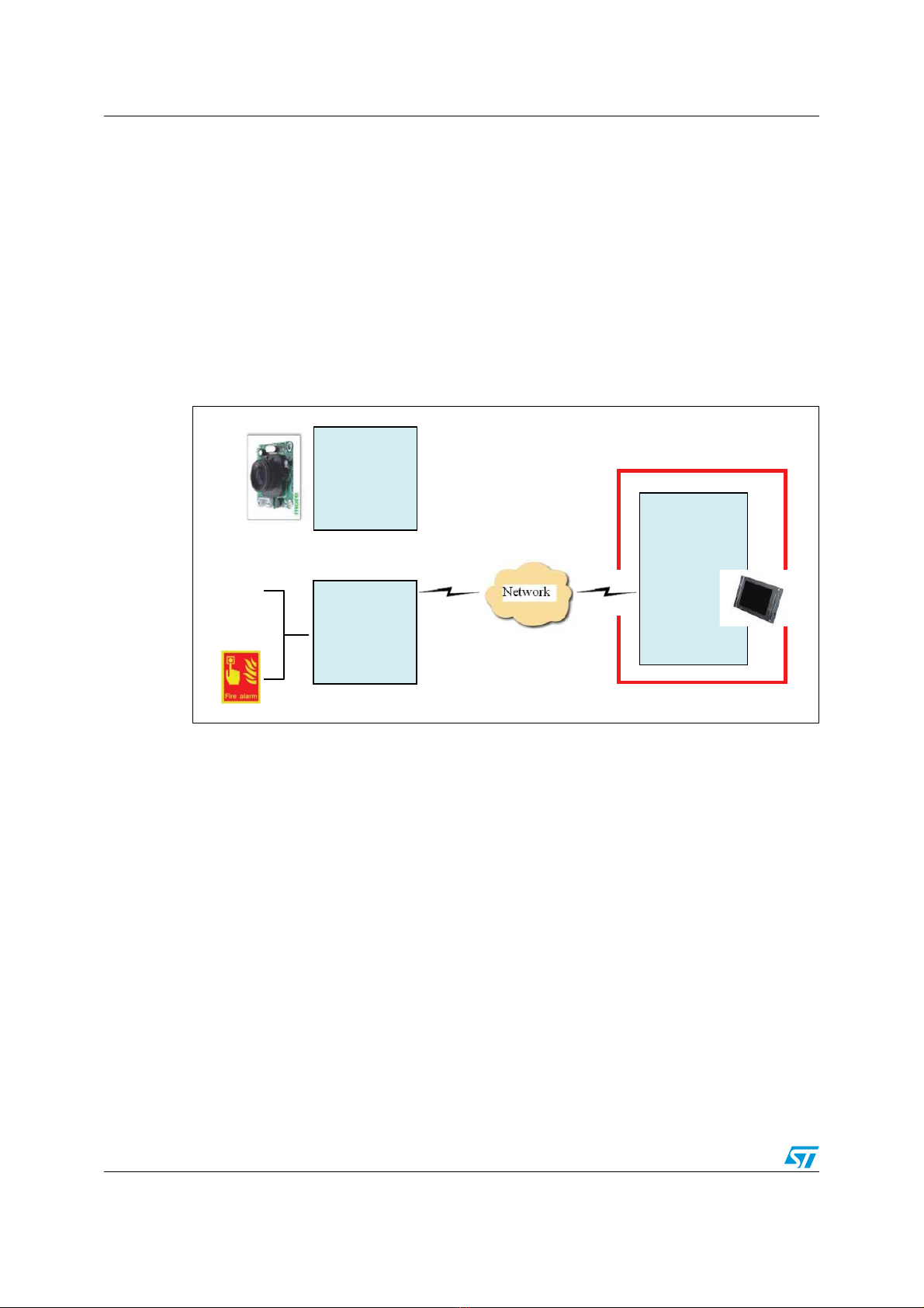
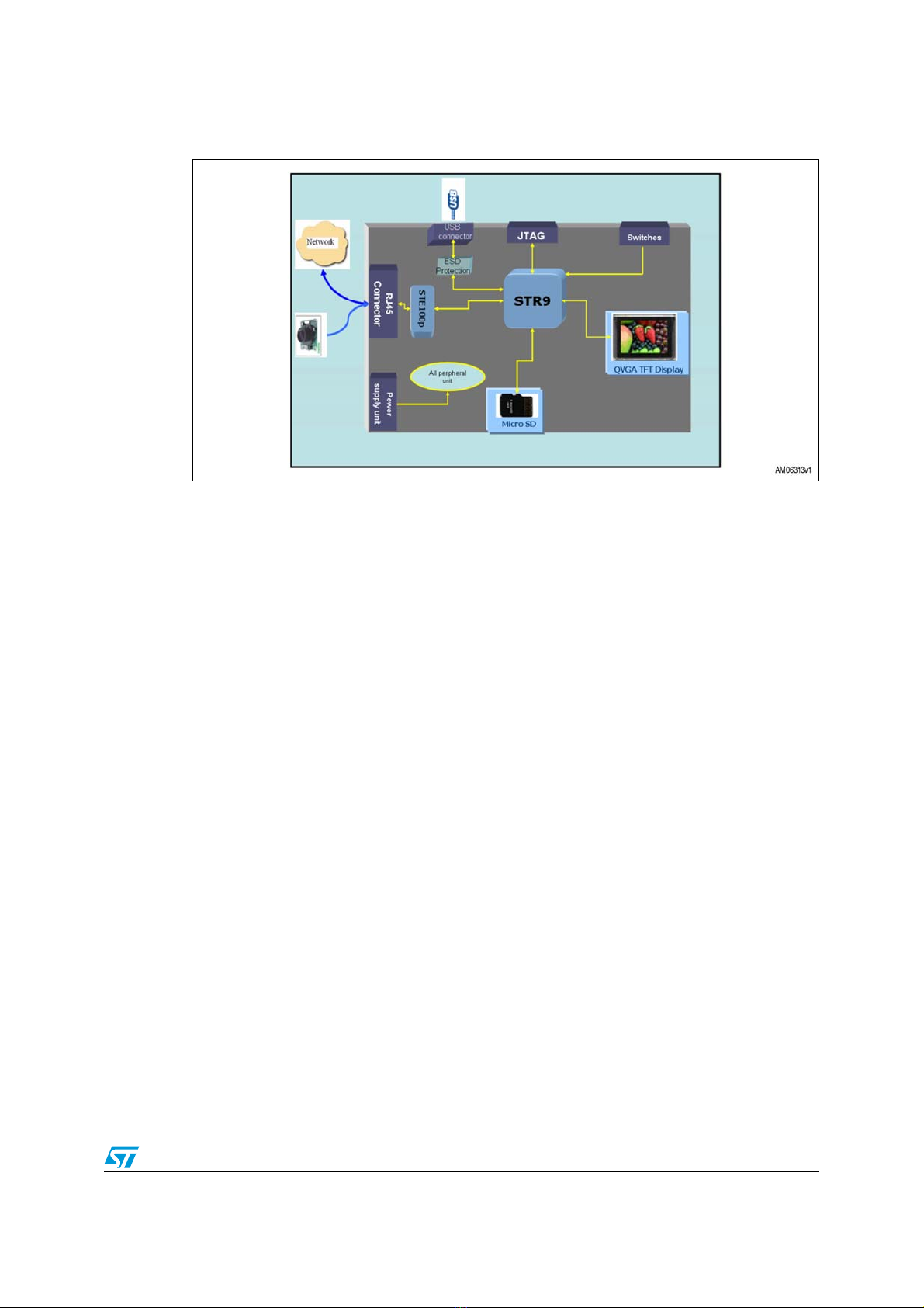
Figure 6. Web-client architecture
The individual parts of the system are described in the following sections.
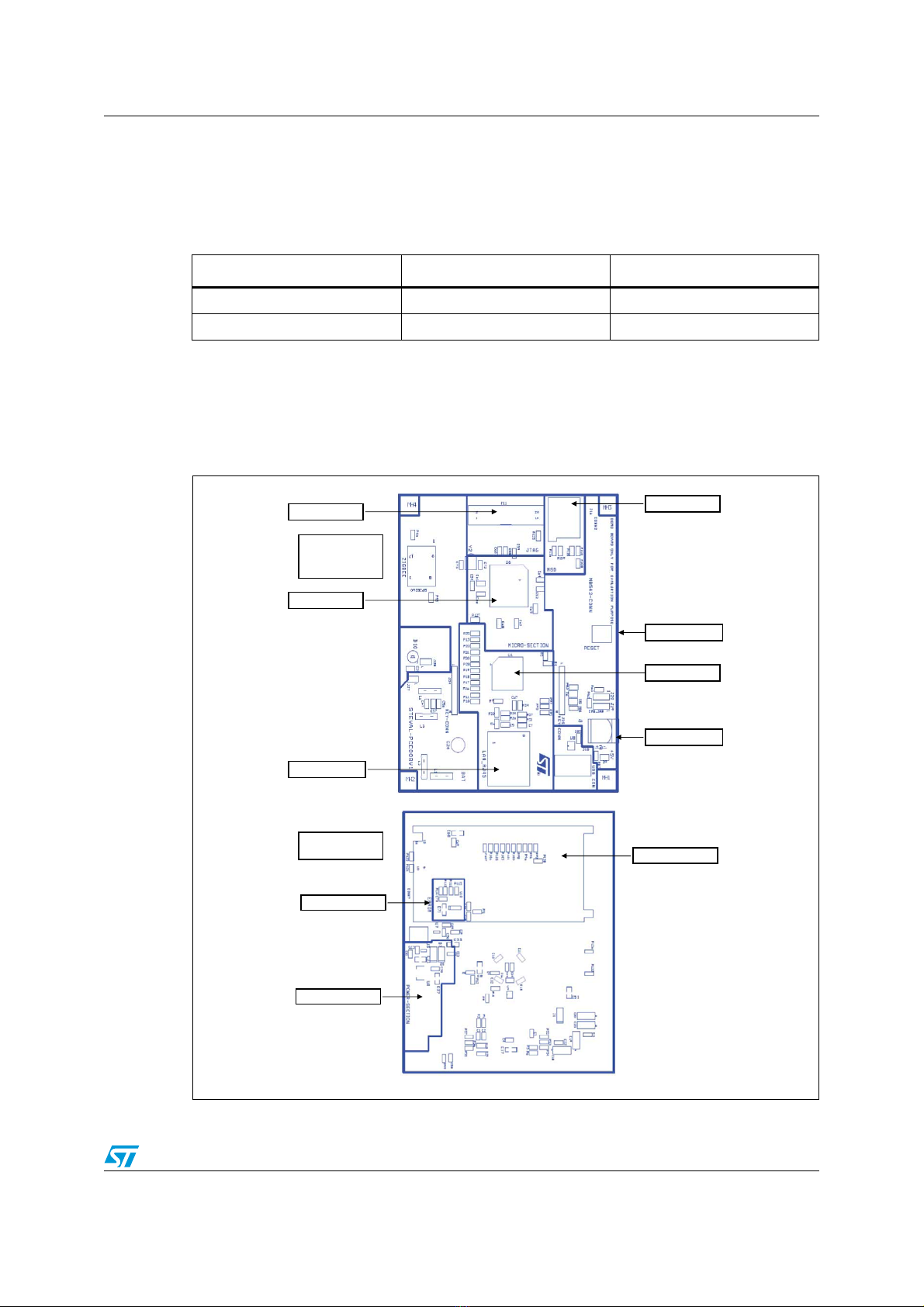
2.2.1 STR9 microcontroller
The system is based on the STR912FAW44X6 microcontroller. The STR9 is a 16/32-bit
96 MHz ARM9E-based MCU having a RISC core, 5-stage pipeline, and tightly coupled
memories. The STR912FAW44X6 has 512 kbytes of main Flash and 96 kbytes of SRAM. It
has many communication interfaces. For more details refer to
http://www.st.com/mcu/inchtml-pages-str9.html.
Note: The STR9 has two SPI channels. In the demonstration board one SPI is allocated to U2,
where a ZigBee®module can be put, while another SPI is shared between the micro-SD
card and the TFT display.
2.2.2 E-STE100P - single port fast Ethernet transceiver
The E-STE100P, also referred to as the STEPHY1, is a high-performance fast Ethernet
physical layer interface for 10BASE-T and 100BASE-TX applications. It was designed with
advanced CMOS technology to provide a media independent interface (MII) for easy
attachment to 10/100 media access controllers (MAC) and a physical media interface for
100BASE-TX and 10BASE-T. For more details refer to
http://www.st.com/stonline/products/families/communication/wireline/ethernet/ethernet.htm.
2.2.3 TFT: MB542B (AM-240320L8TNQW00H)
The TFT module is based on the TFT from Ampire Co. The resolution of this TFT is QVGA
(320 x 240) resolution. It is diagonally 2.4" in size. The TFT has an amorphous,
transmissive, normally white display format. It has one backlight with 4 ultra-bright white
LEDs.
It has real 262 K color display and supports 5-6-5 and 6-6-6 RGB mode. We are using the
5-6-5 RGB mode means it takes 5, 6, 5 most significant bits for red, green and blue
respectively to form one pixel of data. The internal TFT controller is ILI9320. The TFT
internal RAM capacity is 172,800 bytes to display direct data. Please refer to the detailed
datasheet of the TFT for further details.