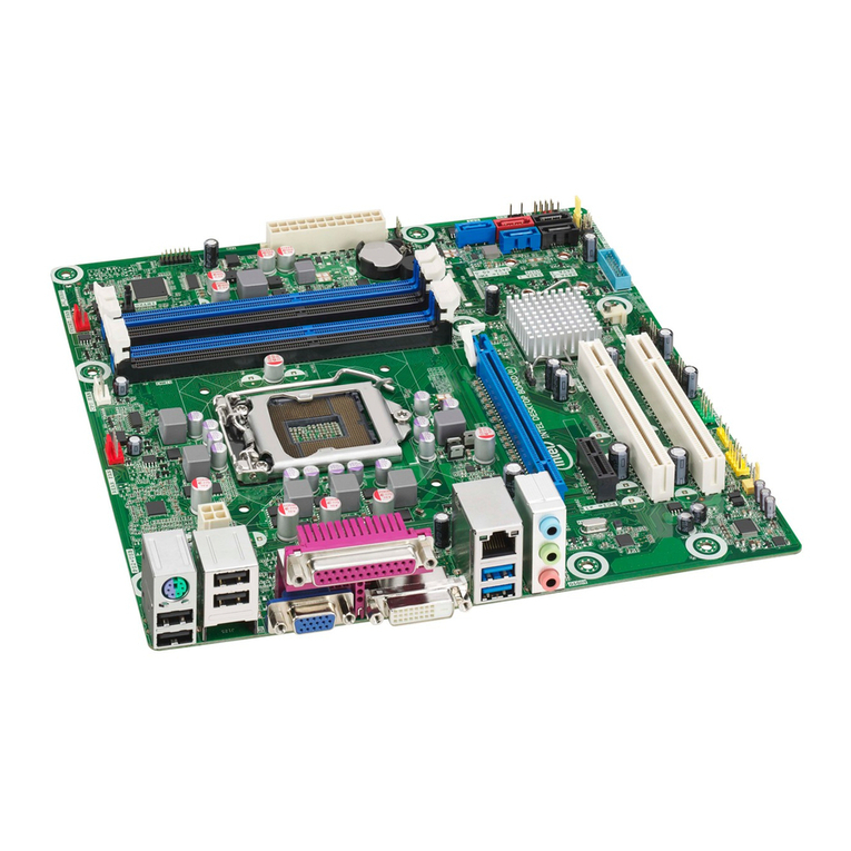
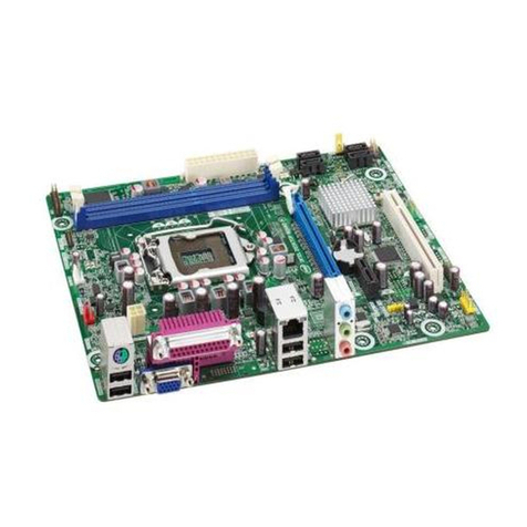
Intel R440LX User manual

R440LX
Server Motherboard
Product Guide

2
Copyright © 1997 Intel Corporation. All rights reserved. No part of this document
may be copied or reproduced in any form, or by any means, without prior written
consent of Intel.
Intel Corporation (Intel) makes no warranty of any kind with regard to this material,
including, but not limited to, the implied warranties of merchantability and fitness
for a particular purpose. Intel assumes no responsibility for any errors that may
appear in this document. Intel makes no commitment to update nor to keep current
the information contained in this document.
This equipment has been tested and verified to Class B limits when in a compatible
host computer, pursuant to Part 15 of the FCC Rules. These limits are designed to
provide reasonable protection against harmful interference in a residential
installation. This equipment generates, uses, and can radiate radio frequency
energy and, if not installed and used in accordance with the instructions, may cause
harmful interference to radio communications. However, there is no guarantee that
interference will not occur in a particular installation. If this equipment does cause
harmful interference to radio or television reception, which can be determined by
turning the equipment off and on, the user is encouraged to try to correct the
interference by one or more of the following measures:
• Reorient or relocate the receiving antenna
• Increase the separation between the equipment and receiver
• Connect the equipment into an outlet on a circuit different from that to which
the receiver is connected
• Consult the dealer or an experienced radio/TV technician for help.
† Third party trademarks are the property of their respective owners.

System Product Guide 3
Contents
1 Motherboard Description
Introduction.............................................................................................. 9
Motheroard Features............................................................................... 9
Motherboard Connector and Component Locations............................ 10
Back Panel Connectors ..................................................................... 11
Microprocessor ........................................................................................ 12
Memory .................................................................................................... 14
Peripherals................................................................................................ 16
Super I/O Chip: Compatibility I/O Controller.............................. 16
Serial Ports......................................................................................... 16
Parallel Port....................................................................................... 16
Diskette Port...................................................................................... 16
Add-in Board Slots .................................................................................. 17
Video......................................................................................................... 18
SCSI Controller ........................................................................................ 18
IDE Controller.......................................................................................... 19
Network Controller................................................................................. 19
Keyboard and Mouse .............................................................................. 20
Server Management................................................................................. 20
System Security........................................................................................ 21
2 Configuring the System
Using the SCU.......................................................................................... 25
Where the SCU Gets Information.................................................... 25
When to Run the SCU....................................................................... 26
Record Your SCU Settings ............................................................... 26
How to Enter and Start the SCU...................................................... 26
Boot from CD and Copy Configuration Software to Diskettes..... 28
Other Tasks You Can Do from the CD Menu.......................... 29
Access the R440LX Server Motherboard Product Guide.............. 29
Six Steps in Using the SCU............................................................... 30
About System Configuration ........................................................... 31
Add and Remove Boards................................................................. 32
Define an ISA Board .................................................................. 33

4Contents
Change Configuration Settings........................................................ 34
Advanced Options ..................................................................... 35
Save Configuration............................................................................ 35
View Switch/Jumper Settings.......................................................... 36
Exit...................................................................................................... 36
SCU Utilities...................................................................................... 36
Configuration Settings for the Motherboard .................................. 38
Server Management.......................................................................... 47
Using Setup .............................................................................................. 48
Record Your Setup Settings.............................................................. 48
If You Cannot Access Setup ............................................................. 49
How to Enter and Start Setup.......................................................... 49
Press <F2> Key to Enter Setup: Prompt Does Not Display.......... 50
Enable <F2> Prompt by Using SCU.......................................... 50
Enable <F2> Prompt by Changing a Jumper and Using SCU 51
Setup Menus...................................................................................... 52
Main Menu......................................................................................... 54
Primary IDE Master and Slave.................................................. 55
Secondary Master and Slave ..................................................... 56
Keyboard Features ..................................................................... 56
Advanced Menu................................................................................ 57
PCI Configuration ...................................................................... 58
Integrated Peripheral Configuration......................................... 60
Security Menu.................................................................................... 62
Server Menu ...................................................................................... 64
System Management.................................................................. 65
Console Redirection ................................................................... 67
Boot Menu.......................................................................................... 68
Boot Device Priority................................................................... 68
Hard Drive.................................................................................. 69
Exit Menu........................................................................................... 69
Using SCSISelect....................................................................................... 70
How to Enter and Start SCSISelect................................................... 70
Main Menu, SCSISelect...................................................................... 71
Configuration Menu, SCSISelect................................................ 72
Boot Device Options, SCSISelect................................................ 73
SCSI Device Configuration, SCSISelect..................................... 74
Advanced Configuration Options, SCSISelect.......................... 76
SCSI Disk Utilities Menu, SCSISelect ........................................ 78
Exit Menu, SCSISelect................................................................. 78
Installing Video Drivers .......................................................................... 79
Configuring the Network Controller...................................................... 79
System Product Guide 5
3 Integrating and Upgrading Hardware
Tools and Supplies Needed .................................................................... 81
Cautions.................................................................................................... 81
Memory, Installing DIMMs .................................................................... 82
Memory, Removing DIMMs................................................................... 83
Drive Cabling Considerations ................................................................ 84
IDE Requirements............................................................................. 84
SCSI Requirements............................................................................ 85
Motherboard, Removing......................................................................... 86
Back-up Battery........................................................................................ 88
Processor, Installing................................................................................. 90
Processor, Removing............................................................................... 94
4 Configuring the Motherboard
Warnings and Cautions........................................................................... 97
Tools and Supplies Needed .................................................................... 98
General Procedure to Change Jumper Setting....................................... 99
Motherboard Jumpers............................................................................. 100
CMOS Clear Jumper......................................................................... 102
Password Clear Jumper.................................................................... 102
Recovery Boot Jumper...................................................................... 103
Boot Block Write Protect Jumper..................................................... 104
Clock Enable Jumper ........................................................................ 104
FRB Timer Enable Jumper................................................................ 105
Chassis Intrusion Detection Jumper................................................ 105
Host Bus In-order Queue Jumper.................................................... 106
5 Updating Flash Memory
System BIOS............................................................................................. 107
Contents of BIOS Update................................................................. 107
User Flash Block................................................................................ 108
Normal BIOS Update Procedure............................................................ 108
Recovery Procedure................................................................................. 109

6Contents
6 Hardware Technical Reference
Terms and Abbreviations........................................................................ 113
Motherboard Environmental Specifications.......................................... 114
System I/O Addresses............................................................................. 115
DOS Compatibility Region...................................................................... 121
Extended Memory Region....................................................................... 121
Interrupts.................................................................................................. 122
Video Modes ............................................................................................ 124
Standard VGA Modes....................................................................... 124
Extended VGA Modes...................................................................... 125
Connectors................................................................................................ 126
Back Panel Connectors............................................................... 128
ATX Power ........................................................................................ 129
Main Power........................................................................................ 129
Auxiliary Power (non-ATX Connector) .......................................... 130
Peripheral Power Connectors........................................................... 131
Diskette Drive.................................................................................... 131
Hard Disk Drive Activity LED ........................................................ 132
Front Panel Connector...................................................................... 132
Fan Interface ...................................................................................... 133
Server Management.......................................................................... 134
IMB..................................................................................................... 135
VGA Video Port ................................................................................ 135
Keyboard and Mouse........................................................................ 136
Parallel Port ....................................................................................... 136
Serial Ports A and B.......................................................................... 137
RJ-45 Network................................................................................... 138
68-Pin Wide/Fast 16-Bit SCSI........................................................... 139
IDE...................................................................................................... 140
ISA...................................................................................................... 141
PCI...................................................................................................... 142
ATX Interface..................................................................................... 143
Declaration of the Manufacturer or Importer........................................ 144
Safety Compliance ................................................................................... 144
Electromagnetic Compatibility (EMC)................................................... 144
Electromagnetic Compatibility Notice (USA)................................. 145
FCC Declaration of Conformity................................................ 146
International Electromagnetic Compatibility Notices.................... 147

System Product Guide 7
7 Information for Computer Integrators
Regulatory Requirements........................................................................ 149
Safety Standards................................................................................ 149
UL 1950 - CSA 950-95, 3rd Edition, July 28, 1995...................... 149
CSA C22.2 No. 950-95, 3rd Edition, July 28, 1995...................... 149
EN 60 950, 2nd Edition, 1992 (with Amendments 1, 2, and 3) . 149
IEC 950, 2nd edition, 1991 (with Amendments 1, 2, 3 and 4)... 149
EMKO-TSE (74-SEC) 207/94..................................................... 149
EMC Regulations .............................................................................. 150
FCC Class B ................................................................................ 150
CISPR 22, 2nd Edition, 1993, Amendment 1, 1995 .................... 150
EN 55 022, 1995........................................................................... 150
EN 50 082-1, 1992 ....................................................................... 150
VCCI Class B (ITE)..................................................................... 150
ICES-003, Issue 2 ........................................................................ 150
Spectrum Management Agency (SMA) — Australian C-Tick
Compliance.............................................................................. 150
New Zealand Ministry of Commerce....................................... 150
Product Certification Markings ....................................................... 151
Installation Instructions........................................................................... 152
Ensure EMC....................................................................................... 152
Ensure Host Computer and Accessory Module Certfications...... 153
Prevent Power Supply Overload..................................................... 154
Place Battery Marking on Computer............................................... 154
Use Only for Intended Applications ............................................... 154
Installation Precautions........................................................................... 155
Index ................................................................................................................... 157

This is a blank page

R440LX Server Motherboard Product Guide 9
Motherboard Description 1
Introduction
The R440LX motherboard provides an entry-level path to server/client
performance based on the Pentium®II processor. The motherboard is
designed to let you upgrade the processor, add RAM, add boards (four PCI,
one ISA), and has standard AT†form factor.
Motherboard Features
Feature Description
Processor Up to two Pentium II processors, packaged in single edge contact
(S.E.C.) cartridges and installed in 242-pin Slot 1 processor
connectors, operating at 1.8 V to 3.5 V. The motherboard's voltage
regulator is automatically programmed by the processor's VID pins
to provide the required voltage.
Memory,
dynamic random
access (DRAM)
Four 72-bit sockets (a total of 32 to 512 MB can be installed) for
SDRAM dual inline memory modules (DIMM)
Video memory
(DRAM) Installed: 1 MB of 60 ns video memory
Read-only
memory (ROM) 512 KB of flash read-only memory to store BIOS and other
information that must be in nonvolatile memory
PCI bus Four PCI expansion slots for add-in boards. 1x32 bit PCI bus.
Embedded devices: video controller, Network Interface Controller
(NIC), and SCSI controller
ISA bus One ISA expansion slot for add-in boards. Embedded PC-
compatible support (serial, parallel, mouse, keyboard, diskette, and
Plug and Play features)
Server
Management Thermal/voltage monitoring and error handling
Real-time clock/calendar (RTC)
Front panel controls and indicators (LEDs)
System Configuration Utility (SCU)
Basic Input/Output System (BIOS), POST, and Setup stored in
flash memory Continued

10 Chapter 1 - Motherboard Description
Feature Description
Graphics Integrated onboard Cirrus Logic CL-GD5446 super video graphics
array (SVGA) controller; 1 MB video memory
SCSI Adaptec†AIC-7880 Wide, Fast-20, PCI 2.1-compliant SCSI
controller
Network Integrated onboard NIC, an Intel 82557 PCI LAN controller for 10 or
100 Mbps TX Fast Ethernet†networks. RJ-45 Ethernet connector
and indicator LEDs at I/O back panel.
Motherboard Connector and Component Locations
AA F
OM06418b
B EA
C
D
GH
Q
M
J
I
KL
N
OR P
Z
X
W
V
S
T
Y
Sec.
Pri.
U
A Slot 1 secondary connector
B Slot 1 primary connector
C Fan heat sink secondary connector
D Fan heat sink primary connector
E Main power connector (from power supply), 24 pin
F Front panel connector, 16 pin
G AT front panel connector

R440LX Server Motherboard Product Guide 11
H Local IMB connector
I Lithium backup battery
J Diskette drive connector
K System fan 1 connector
L IDE connectors, primary (labeled IDE1) and secondary (labeled IDE2)
M Configuration jumper blocks
N System fan 2 connector
O Server monitor mechanism (SMM) connector
P Wide SCSI connector
Q Hard drive LED connector
R ISA slot for add-in board (one)
S PCI slots for add-in boards (four); slot 1 is closest to ISA slot
T Memory sockets for four DIMM components; socket 4 is closest to PCI slots
U Chassis intrusion switch connector
V RJ-45 network controller*
W Serial port B (COM 2)
X VGA†monitor port*
Y Parallel port*
Z Serial A (COM 1)*
AA Keyboard and Mouse PS/2†compatible connectors (interchangeable)*
* See “Back Panel Connectors,” below.
Back Panel Connectors
OM06705
B
D
F
A
C
E
G
A Network controller LEDs
Activity (top)
Link (middle)
Speed (bottom)
B RJ-45 network connector port
C VGA, 15-pin video connector
D Serial port A, 9-pin connector (COM1)
E PS/2-compatible keyboard port, 6-pin
miniature Deutsche Industrie Norm (DIN)
connector (interchangeable with mouse
port)
F PS/2-compatible mouse port, 6-pin DIN
connector (interchangeable with
keyboard port)
G Parallel port (LPT1), 25-pin connector

12 Chapter 1 - Motherboard Description
Microprocessor
Processors are not included with the R440LX motherboard and must be
purchased separately. The motherboard supports up to two Intel
Pentium II processors. Each processor is packaged in a Single Edge Contact
(S.E.C.) cartridge. The cartridge includes the processor core operating at
233, 266, or 300 MHz with an integrated 32 KB (16 KB data, 16 KB
instruction) primary (L1) cache; the secondary (L2) cache; a thermal plate;
and a back cover. The 300 MHz processor with Error Correcting Code
(ECC) on the L2 cache is recommended for dual processing applications. If
you are installing two processors, make sure they have:
• Identical speeds and second-level cache sizes. The speed and cache size
are printed on the top edge of the processor.
• Identical steppings of not more than one stepping apart. The stepping is
designated by a 5-letter code, i.e., SL28R, printed on the top edge of the
processor.
The S.E.C. cartridges are mounted in a dual-processor retention mechanism,
which is provided with the R440LX motherboard. When you buy a boxed
processor to install on the motherboard, it comes with parts that are not
necessary for installation. The retention mechanism is keyed to ensure
correct orientation and is mounted with four screws, which are also
provided.
Pentium II processors implement the MMX™technology and maintain full
backward compatibility with the 8086, 80286, Intel386™, Intel486™, Pentium,
and Pentium Pro processors. The processor’s numeric coprocessor
significantly increases the speed of floating-point operations and complies
with ANSI/IEEE standard 754-1985.

R440LX Server Motherboard Product Guide 13
The processor external interface (GTL+ Pentium II processor bus) is MP-
ready and operates at 66 MHz. The processor contains a local APIC section
for interrupt handling in MP and UP environments.
The L2 cache is located on the substrate of the S.E.C. cartridge. The cache
includes burst pipelined synchronous static RAM (BSRAM). The L2 cache is
offered in 512 KB configurations only, with ECC that operates at half the
core clock rate.
CAUTION, single-processor configurations
If you install only one processor in a system, it must go in the Slot 1
primary connector (closest to the DIMM sockets and the center of
the motherboard). In a single-processor configuration, you must
install a termination board in the empty Slot 1 secondary connector
(closest to the edge of the motherboard) to ensure proper operation
of your system. A termination board is provided with the R440LX
motherboard. See Chapter 3, “Integrating and Upgrading
Hardware.”
CAUTION, do not overtighten screws
The four screws used to attach the retention mechanism to the
motherboard should not be tightened to more than six inch-pounds
of torque. See Chapter 3, “Integrating and Upgrading Hardware.”

14 Chapter 1 - Motherboard Description
Memory
Only SDRAM is supported by the motherboard. Memory is partitioned as
four banks of SDRAM DIMMs, each providing 72 bits of noninterleaved
memory (64-bit main memory plus ECC):
• Install from 32 MB to 512MB of memory, using up to four single- or
double-banked DIMMs.
Installed DIMMs must be the same speed.
Dual address strobe (RAS) signals are provided for each DIMM. When
single-banked DIMMs are used, one of the RAS lines is connected to both
36-bit “halves” of the DIMM. When double-banked DIMMs are used
(known as Dual RAS), both RAS lines are connected to two 36-bit “quarters”
of the DIMM.
Some operating systems and application programs use base memory—for
example, MS-DOS†, OS/2†, and UNIX†. Other operating systems use both
conventional and extended memory—for example, OS/2 and UNIX.
MS-DOS does not use extended memory; however, some MS-DOS utility
programs such as RAM disks, disk caches, print spoolers, and windowing
environments use extended memory for better performance.
The controller automatically detects, sizes, and initializes the memory array,
depending on the type, size, and speed of the installed DIMMs, and reports
memory size and allocation to the system via configuration registers.

R440LX Server Motherboard Product Guide 15
✏DIMM sizes and compatibility
We do not test every possible combination of DIMM sizes
and vendors. To avoid potential memory problems, use
DIMMs that have been tested for compatibility with the
motherboard. The table below lists some sample size
combinations. Contact your sales representative or dealer
for more information about your system.
Sample DIMM Component Combinations
Bank 0
(slot J1) Bank 1
(slot J2) Bank 2
(slot J3) Bank 3
(slot J4) Total
memory
32 32 MB
32 32 64 MB
32 32 128 192 MB
32 32 128 128 320 MB
32 128 128 128 416 MB
128 128 128 128 512 MB

16 Chapter 1 - Motherboard Description
Peripherals
Super I/O Chip: Compatibility I/O Controller
The National Semiconductor PC87307VUL Super I/O chip (87307) supports
two serial ports, one parallel port, diskette drive, PS/2-compatible keyboard
and mouse, and integrated RTC. The motherboard provides the connector
interface for each port.
Serial Ports
Both serial ports are relocatable. By default, port A appears at the onboard
DB9 connector, port B on the 10-pin header. Each serial port can be set to
one of four different COMx ports and can be enabled separately. When
enabled, each port can be programmed to generate edge- or level-sensitive
interrupts. When disabled, serial port interrupts are available to add-in
boards.
Parallel Port
The 87307 provides one IEEE 1284-compatible 25-pin bidirectional EPP
(supporting levels 1.7 and 1.9). BIOS programming of the 87307 registers
enable the parallel port and determine the port address and interrupt.
When disabled, the interrupt is available to add-in boards.
Diskette Port
The floppy disk controller (FDC) on the 87307 is functionally compatible
with 82077SL, 82077AA, and 8272A diskette drive controllers. The
motherboard provides the 24 MHz clock, termination resistor package, and
chip selects. All other FDC functions are integrated into the 87307,
including PLL separator and 16-byte first-in, first-out (FIFO).

R440LX Server Motherboard Product Guide 17
Add-in Board Slots
The motherboard has one full-length dedicated ISA bus slot, which can have
a bus master in it. ISA features:
• Bus speed up to 8.33 MHz
• 16-bit memory addressing
• Type A transfers at 5.33 Mbps
• Type B transfers at 8 Mbps
• 8- or 16-bit data transfers
• Plug and Play ready
The motherboard also has four dedicated full-length PCI slots. PCI features:
• Bus speed up to 33 MHz
• 32-bit memory addressing
• 5 V signaling environment
• Burst transfers of up to 133 Mbps
• 8-, 16-, or 32-bit data transfers
• Plug and Play ready
• Parity enabled

18 Chapter 1 - Motherboard Description
Video
The onboard, integrated Cirrus Logic CL-GD5446 32-bit VGA contains a
clock generator, an 80 MHz RAMD AC in a 208-pin plastic quad flat pack
(PQFP), and an SVGA controller that is fully compatible with these video
standards: CGA†, EGA†, Hercules†Graphics, MDA†, and VGA. Standard
video memory consists of two 256 K x 16 DRAM chips providing 1 MB of
60 ns video memory. The 5446 supports a variety of modes: up to
1280 x 1024 resolution, and up to 64 K colors.
This SVGA subsystem supports analog VGA monitors, single and multi-
frequency, interlaced and non-interlaced, up to 87 Hz vertical retrace
frequency. The connector is a standard 15 pin VGA connector.
The SVGA controller supports analog VGA monitors (single and multiple
frequency, interlaced and noninterlaced) with a maximum vertical retrace
interlaced frequency of 87 Hz.
You cannot add memory to this motherboard. Depending on the
environment, the controller displays up to 64 K colors in some video
resolutions. It also provides hardware-accelerated bit block transfers
(BITBLT) of data.
SCSI Controller
The motherboard includes an Adaptec AIC-7880 wide/fast-20, SCSI III
compatible controller chip that is integrated as a PCI bus master. The
adapter supports 8- or 16-bit Fast SCSI that provides 10 or 20 MB/sec
throughput, or Fast-20 Wide SCSI that can burst data at 20 or 40 MB/sec.
No logic, termination, or resistor loads are required to connect devices to
the SCSI controller other than termination in the device at the end of the
cable. The SCSI bus is terminated on the motherboard with active
terminators that cannot be disabled. The onboard device must always be at
one end of the bus.

R440LX Server Motherboard Product Guide 19
IDE Controller
IDE is a 16-bit interface for intelligent disk drives with AT disk controller
electronics onboard. The PCI/ISA/IDE Accelerator, also known as PIIX4, is
a multifunction device on the motherboard that acts as a PCI-based Fast IDE
controller. The device controls:
• PIO and IDE DMA/bus master operations
• Mode 4 timings
• Transfer rates up to 22 MB/sec
• Buffering for PCI/IDE burst transfers
• Master/slave IDE mode
• Up to two drives per channel; two channels, IDE0 and IDE1
✏18-inch maximum length of IDE cable on each channel
You can connect an IDE signal cable, up to a maximum of
18 inches each, to each IDE connector on the motherboard.
Each cable can support two devices, one at the end of the
cable and one 6 inches from the end of the cable.
Network Controller
The motherboard includes an integrated NIC, which is the Intel 82557 PCI
LAN Controller for 10 or 100 Mbps TX Fast Ethernet networks. The
network ID is stored in an EEPROM on the motherboard. As a PCI bus
master, the controller can burst data at up to 133 MB/sec. The controller
contains two receive and transmit FIFO buffers that prevent data overruns
or underruns while waiting for access to the PCI bus. The controller has the
following:
• 32-bit PCI bus master interface (direct drive of bus), compatible with
PCI Bus Specification, Revision 2.1
• Chained memory structure with improved dynamic transmit chaining
for enhanced performance
• Programmable transmit threshold for improved bus utilization
• Early receive interrupt for concurrent processing of receive data
• On-chip counters for network management
• Autodetect and autoswitching for 10 or 100 Mbps network speeds
• Support for both 10 Mbps and 100 Mbps networks, capable of full or
half duplex, with back-to-back transmit at 100 Mbps
The network status LEDs on the motherboard indicate:
• Transmit/receive activity on the LAN
• Valid link to the LAN
• 10/100 Mbps transfer mode

20 Chapter 1 - Motherboard Description
Keyboard and Mouse
The keyboard/mouse controller is PS/2-compatible. The system may be
locked automatically if there is no keyboard or mouse activity for a
predefined length of time, if specified through the SCU. Once the inactivity
(lockout) timer has expired, the keyboard or mouse does not respond until
the previously stored password is entered.
Server Management
Server Management features are implemented using three microcontrollers
and one PLD:
• Motherboard Management Controller (BMC)
• Front Panel Controller (FPC)
• Processor Board Controller (PBC)
• Distributed Integrated Server Management Interface Controller
(DISMIC)
BMC—The BMC is an 8051-compatible microcontroller located on the
motherboard. The BMC monitors motherboard power supply and SCSI
termination voltages using an external Analog to Digital Converter (ADC);
the BMC checks the status of the fan failure indicators. The BMC also
monitors system temperature sensors on the intelligent management bus.
When any monitored parameter is outside defined thresholds, the BMC
generates a system management interrupt (SMI). The BMC also provides
general-purpose I/O (GPIO) functions and acts as the primary
communications gateway to the FPC, PBC, and DISMIC by providing
support routines for IMB and ISA communications
An EEPROM associated with the secondary motherboard temperature
sensor contains the values for the chassis ID, motherboard ID, power state,
and motherboard temperature during power-off conditions. The BMC
manages these values via IMB.
FPC—The FPC, located on the motherboard, manages system power on/off
control, system reset, and front panel NMI buttons, along with an external
IMB interface. The +5V standby power supply powers the device so that it
retains power even when system power is off. The FPC controls main
power to the motherboard and is responsible for monitoring all sources of
power control both on and off the motherboard, including the Front Panel,
Server Monitor Mechanism, PIIX4, and RTC power control signals. The
FPC also detects chassis intrusion by monitoring an external switch and
remembers the last power state if AC power is unterrupted.
Table of contents
Other Intel Motherboard manuals

Intel
Intel D945PLRN User manual

Intel
Intel BX80623I52500 User manual

Intel
Intel D945PAW User manual

Intel
Intel D945GNT User manual

Intel
Intel DH67CF User manual

Intel
Intel DQ57TM User manual

Intel
Intel DDR266 (PC2100) User manual

Intel
Intel DH61CR User manual

Intel
Intel DX79SI User manual

Intel
Intel D2500CC User manual

Intel
Intel D955XBK User manual

Intel
Intel D845GVSR - Desktop Board Motherboard User manual

Intel
Intel D845PT User manual

Intel
Intel DQ965WC User manual

Intel
Intel iSBC 80 Quick user guide

Intel
Intel D848PMB User manual

Intel
Intel i865-G User manual

Intel
Intel Celeron 847 User manual

Intel
Intel D945GBO User manual

Intel
Intel VX PENTIUM PCI User manual