manuals.online logo
Brands
  1. Home
  2. •
  3. Brands
  4. •
  5. Intelight
  6. •
  7. Lighting Equipment
  8. •
  9. Intelight STARLET WHITE SO User manual

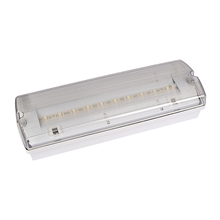
Intelight STARLET WHITE SO User manual

IP20
INSTRUCTION MANUAL
General remarks
1. The installation of this product must be done in accordance to the information enclosed in this
manual and carried out by a qualied electrician
2. Before installation make sure that electrical supply line is isolated.
3. Before operation please check if the voltage of mains supply is same as the input voltage of this
product.
4. This tting is supplied with the Ni-Cd battery pack, not pre-charged.
5. The product needs to be charged for 24 hours before rst emergency operation. If not used regularly,
it should be charged every three months.
6. The battery should be changed after the luminaire no longer meets its rated duration. It is recom-
mended to change it minimum every four years.
7. The product is delivered with an open space lens as a standard. If a corridor lens is needed, a separate
kit consisting of a lens and a lens cover must be ordered for replacement.
Characteristics
Rated voltage: 220-240VAC 50/60 Hz
Light source (non-replaceable): Power LED 3W or 5W
Max power *: 3W - 9W
Luminous ux *: 110lm (for 3W) or 188lm (for 5W)
Battery pack (replaceable) *: Ni-Cd, 3.6V 3Ah HT (for 3W) or 3.6V 4.5Ah HT (for 5W)
Emergency autonomy: min. 3h
Full charge time: max 24h
Ambient temperature: +10°C - +55 °C
Module: Starlet White
Operating modes: SA (M) - maintained or A (NM) - non-maintained
Test functionality: MT - maunual test or AT - autotest
* depending on version
STARLET WHITE
versions: SO & SC; M/NM & NM; 3W & 5W; MT & AT
Pursuant to the Act of 29 July 2005 on
waste electrical and electronic equipment
and the Act of 24 April 2009 on batteries
and accumulators, the presented device,
after use, due to hazardous substances
contained in it, is subject to collection of
waste electrical and electronic
equipment. Detailed information on
WEEE collection can be obtained from
municipal authorities
Handling of obsolete equipment
Intelight Sp. z o.o.
8 Rydygiera str.
01 -793 Warsaw, Poland
LED indicator
The green LED indicator is located on the front surface of the LED lamp head. The LED indicates the
mains supply is ON and is healthy and the battery is charging. It should be always ON when the mains
supply is ON.
When the lamp is in auto-test mode, LED indicator becomes red.
If LED indicator starts ashing red it signals a battery failure. In a case of quick ashing red it informs
about shorter than nominal autonomy time.
Manual test
(Concerns versions with manual test function)
Pressing and keeping the button on lamp head makes it passing into emergency mode. Green LED
indicator stops lighting, LED lamp will light using battery power instead of mains supply. Releasing the
button stops manual testing.
Auto test
(Concerns versions with auto test function.)
After emergency lamp is installed it will perform automatic tests:
1. Function test
It will be conducted once monthly for 10 min. The testing checks if the lamp is healthy and ready for
emergency operation. After 10 min. it will go back to normal operation.
2. Autonomy test
It will be conducted once yearly during nominal lamp autonomy time (e.g. 3 h).This testing checks if the
lamp is healthy and its autonomy time equals to the rated nominal value (e.g. mentioned 3 h). After the
test is nished, the lamp will go back to normal operation.
Function of a manual switch
In auto test versions, the manual switch on the lamp head has two functions:
1. Pressing the button for 1 s initiate timing start.
2. Pressing the button for 3 s lights LED indicator and initiate auto test procedure for 5 min.
KTM 97143 - Instruction Starlet White, EN ver. 20171129
INSTALLATION INSTRUCTION
The installation must be done in accordance to the following points and corresponding
drawings. The battery must not be covered by an insulation or any other material which
might cause it to overheat.
1. Hole in ceiling
Drill an appropriate (Ø70-75mm) hole in the ceiling. The maximum ceiling thickness is 10mm.
2. Terminal cover
Open terminal cover.
3. Terminal connections
Connect the mains supply to the tting according to the information below, the tting must have
a permanent mains supply to keep the battery fully charged.
Terminal LIVE (L) – to be connected to power supply directly (phase L, usually brown or black
wire). Switching power supply on is signalled by lighting of green LED indicator on lamp head.
Switching power supply o implies passing into emergency mode.
Terminal NEUTRAL (N) – to be connected to neutral wire (N, blue wire).
Terminal EARTH (E) – to be connected to protection earth wire (PE, yellow and green wire). Such
basic wiring allows to lamp to work in non-maintained mode (“NM”). Connect a switched life
(marked “Ls”) if the unit is required to operate in the maintained mode (“M”).
Terminal Ls – or Lsw or L1, is used to choose emergency mode: NM-non-maintained or
M-maintained. If lamp should work in NM mode then terminal “Ls” must be left not connected. If
lamp should work in M mode then terminal “Ls” must be connected to terminal “L” (i.e. phase “L”
must be connected also to “Ls”).
4. Connecting tting parts together
Connect both lamp head and battery pack to electronic module using dedicated wired connec-
tors.
5. Hiding electronics and battery
Feed the module and battery through the hole in the ceiling and spread them on the ceiling
evenly.
6. Installing lamp head.
Fix the lamp head in a target position using two spring clips.
7. Connecting mains supply
Switch on the mains supply and check if the green LED is ON (take care not to look directly into
high brightness LED as this could cause a damage to the eyes).

This manual suits for next models

7

Other Intelight Lighting Equipment manuals

Intelight ORION LED 100 User manual

Intelight

Intelight ORION LED 100 User manual

Intelight VELLA User manual

Intelight

Intelight VELLA User manual

Popular Lighting Equipment manuals by other brands

Lighttoys Visual Poi V4 user manual

Lighttoys

Lighttoys Visual Poi V4 user manual

EuroLite LED PFE-10 user manual

EuroLite

EuroLite LED PFE-10 user manual

ETC Express 24/48 user manual

ETC

ETC Express 24/48 user manual

Quoizel RAM8405MBK installation guide

Quoizel

Quoizel RAM8405MBK installation guide

Aeotec ZW098 manual

Aeotec

Aeotec ZW098 manual

LDR Suono f650 plus white operating instructions

LDR

LDR Suono f650 plus white operating instructions

Aspar EVO-15 Technical documentation

Aspar

Aspar EVO-15 Technical documentation

luceco LBM290W11E40 Installation & operating instructions

luceco

luceco LBM290W11E40 Installation & operating instructions

Miboxer Mi-Light FUT105Z quick guide

Miboxer

Miboxer Mi-Light FUT105Z quick guide

Chauvet Maverick MK2 Wash user manual

Chauvet

Chauvet Maverick MK2 Wash user manual

IMG Stage Line SCAN-20LED instruction manual

IMG

IMG Stage Line SCAN-20LED instruction manual

Chauvet Colordash Block user manual

Chauvet

Chauvet Colordash Block user manual

wofi 11557 installation instructions

wofi

wofi 11557 installation instructions

Klus NABU-FIO Mounting instructions

Klus

Klus NABU-FIO Mounting instructions

MELINERA Z31656A Operation and safety notes

MELINERA

MELINERA Z31656A Operation and safety notes

Pond Boss L6MIN instruction sheet

Pond Boss

Pond Boss L6MIN instruction sheet

BiiWheel NaturalShine Half Egg 1500 NG-3 instruction manual

BiiWheel

BiiWheel NaturalShine Half Egg 1500 NG-3 instruction manual

Chauvet Well Flex user manual

Chauvet

Chauvet Well Flex user manual

manuals.online logo
manuals.online logoBrands
  • About & Mission
  • Contact us
  • Privacy Policy
  • Terms and Conditions

Copyright 2025 Manuals.Online. All Rights Reserved.