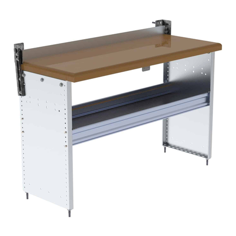
Intelitek JobMaster 00-1800 Series User manual

JobMaster® Mechanical Training Bench
QUICK START GUIDE
For the New 00-1800 Series Benches
Catalog #34-8000-0016 Rev. F

Copyright © 2022 Intelitek Inc.
JobMaster Mechanical Bench Quick Start Guide
Cat. # 34-8000-0016 Rev. F
November 2022
website: http://www.intelitek.com
email: [email protected]
Intelitek software and documentation are available at http://intelitekdownloads.com.
Tel: (603) 625-8600
Fax: (603) 437-2137
All rights reserved. No part of this publication may be stored in a retrieval system, or reproduced in any way,
including but not limited to photocopy, photography, magnetic, or other recording, without the prior agreement and
written permission of the publisher. Program listings may be entered, stored, and executed in a computer system,
but not reproduced for publication.
Every effort has been made to make this book as complete and accurate as possible. However, no warranty of
suitability, purpose, or fitness is made or implied. Intelitek is not liable or responsible to any person or entity for loss
or damage in connection with or stemming from the use of the software, hardware and/or the information
contained in this publication.
Intelitek bears no responsibility for errors that may appear in this publication and retains the right to make changes
to the software, hardware and manual without prior notice.

Table of Contents
1. In This Guide .........................................................................................................................................................4
1.1. Overview ....................................................................................................................................................................... 4
1.2. Version Update: Main Differences ................................................................................................................................ 4
2. List of Accessories .................................................................................................................................................5
3. Mounting and Assembly .......................................................................................................................................6
3.1. Mounting onto a Table.................................................................................................................................................. 6
3.2. Mounting onto the Mobile Bench ................................................................................................................................. 9
3.2.1. Assembling the Mobile Bench........................................................................................................................................................9
3.2.2. Assembling the Shelves..................................................................................................................................................................9
3.2.3. Assembling the Working Surface..................................................................................................................................................10
3.3. Motor Controller and Safety Guard Assembly............................................................................................................. 12
4. Operating the Motor...........................................................................................................................................15
5. Mounting Training Bench Accessories ................................................................................................................19
5.1. Overview ..................................................................................................................................................................... 19
5.2. Map for Assembly Mounting....................................................................................................................................... 20
5.3. Mounting Bearing Kit Accessories ............................................................................................................................... 20
5.4. Mounting Laser Alignment Accessories....................................................................................................................... 22

4
JobMaster® Mechanical Training Bench|In This Guide
© 2022 Intelitek Inc. All rights reserved | 34-8000-0016-F-JM-Mechanical-Bench-QS_v1.1
1. In This Guide
1.1. OVERVIEW
Thank you for purchasing the JobMaster Mechanical Training Bench for use in your classroom or
laboratory. This guide is meant to help you assemble the bench and prepare it for use with the online
learning curriculum.
1.2. VERSION UPDATE: MAIN DIFFERENCES
The main differences between this version of the Mechanical Bench and the previous version (00-ME10
series) are related to:
•Modularity: This version of the Mechanical Bench includes plastic containers with equipment
that can be placed on the shelves of the bench. Different levels of equipment may be purchased,
and containers can be moved, interchanged, or stored elsewhere. For more information about
the different levels of modularity, see Section 2 List of Accessories.
•Safety: With the introduction of a new magnetic key/lock system, the motor can only run when
the plexiglass enclosure is securely in place. See Section 3.3 Motor Controller and Safety Guard
Assembly for more information.
•Motor Controller: The motor controller has been updated. For instructions on its use, see
Section 4 Operating the Motor.
•Materials: The previous version of the Mechanical Bench contained rigid metal racks and an
inflexible working surface. The 00-1800 series is made up of more flexible and user-friendly
materials.

5
JobMaster® Mechanical Training Bench|List of Accessories
© 2022 Intelitek Inc. All rights reserved | 34-8000-0016-F-JM-Mechanical-Bench-QS_v1.1
2. List of Accessories
You may have purchased additional, optional Mechanical Training Bench accessories. You can find a list
of these accessories in this table.
Part
Cat. No.
Level
Working Surface
00-1800-0002
1
Coupling Kit
10-1800-0002
1
Shaft & Bearing Kit
10-1800-0003
1
Accessories Kit 1
10-1800-0004
1
Sheave, Pulley, & Sprocket Kit
10-1800-0005
2
Motor Kit
10-1800-0006
2
Accessories Kit 2
10-1800-0007
2
Gear Kit
10-1800-0008
3
C-Brake/Speed Reducer Kit
10-1800-0009
3
Gearbox Kit
10-1800-0010
3
Tool Set
10-1800-0020
1
Mobile Bench
00-1800-0001
Optional
Shelf Set
10-1800-0001
Optional
Bearing Kit
00-1800-6000
Optional

6
JobMaster® Mechanical Training Bench|Mounting and Assembly
© 2022 Intelitek Inc. All rights reserved | 34-8000-0016-F-JM-Mechanical-Bench-QS_v1.1
3. Mounting and Assembly
The JobMaster Mechanical Training Bench’s working surface (catalog #00-1800-0002) can be mounted
onto a standard table/bench or onto the JobMaster Mechanical Training Bench’s mobile bench (00-
1800-0001). The two sections below (3.1 Mounting onto a Table immediately below and 3.2 Mounting
onto the Mobile Bench on page 9) describe how to mount the working surfaces onto the respective
fixtures.
3.1. MOUNTING ONTO A TABLE
This section provides instruction for attaching the working surface onto an existing table in your work
area. A fully equipped table-mounted working surface is shown in the image below.
For instructions on how to mount the working surface onto the mobile bench, see section 3.2 Mounting
onto the Mobile Bench on page 9.
Warning: The working surface should only be lifted and moved by two
people, one at each side.
Warning: Never drag the working surface, as dragging may damage it
and/or the surface beneath it. Always lift the working surface when moving
it from place to place.

7
JobMaster® Mechanical Training Bench|Mounting and Assembly
© 2022 Intelitek Inc. All rights reserved | 34-8000-0016-F-JM-Mechanical-Bench-QS_v1.1
Warning: Ensure that the table or bench that you intend to use for the
mounting of the working surface is large and sturdy enough to support the
working surface when it is fully loaded with equipment. When fully
equipped, the working surface can collapse the table if it is not wide enough
or sturdy enough to support the weight. Recommended surfaces should be
rated to support at least 100 kg (220 lbs.) and have minimum dimensions of
1500 mm x 500 mm. Surface thickness must be between 20 mm and 40 mm.
Read the mounting instructions in this section before selecting a table.
Additional length and/or width may be required depending on the structure
of the table itself. You may also want to consider the properties of the table
with regard to storage space, ease of access, and mobility. You will be
drilling holes into the table and then securing the working surface with
screws and washers, which are included.
To mount the working surface onto a table or bench:
Note: For detailed diagrams of the assembly and part numbers of the fasteners, see document
101970 (sub-document D00-1800-0002).
1. Choose an appropriately sized (minimum dimensions 1500 mm x 500 mm) and sturdy table.
2. Using a pencil, mark four targets for drilling, as shown in this diagram.
3. Using a power drill with the appropriately sized drill bits, drill four holes, each 12 mm in
diameter, into the targets on the table.
4. Carefully lift the working surface and place it onto the table. Center each of the four legs
(vertical profiles) on top of the four holes.

8
JobMaster® Mechanical Training Bench|Mounting and Assembly
© 2022 Intelitek Inc. All rights reserved | 34-8000-0016-F-JM-Mechanical-Bench-QS_v1.1
5. Use the four M8x50 socket button head cap screws and the flat washers included in the package,
and a hex wrench to secure each of the working surface’s legs to the table. The order of the
assembly, from bottom to top, is screw head, square washer, tabletop, working surface leg
(profile).

9
JobMaster® Mechanical Training Bench|Mounting and Assembly
© 2022 Intelitek Inc. All rights reserved | 34-8000-0016-F-JM-Mechanical-Bench-QS_v1.1
3.2. MOUNTING ONTO THE MOBILE BENCH
The JobMaster Mechanical Training Bench includes two main sections: the main mobile bench (00-1800-
0001) with shelves (10-1800-0001), and the working surface (00-1800-002).
This section provides instruction for assembling the mobile bench (with shelves) and for mounting the
working surface onto the mobile bench. For instructions on how to mount the mobile bench onto a pre-
existing table, see above section 3.1 Mounting onto a Table on page 6.
3.2.1. Assembling the Mobile Bench
Unpack and assemble the mobile bench (00-1800-0001) according to the instructions in document
101969.
3.2.2. Assembling the Shelves
Assemble the shelve set (10-1800-0001) onto the mobile bench according to the instructions in
document 101970.

10
JobMaster® Mechanical Training Bench|Mounting and Assembly
© 2022 Intelitek Inc. All rights reserved | 34-8000-0016-F-JM-Mechanical-Bench-QS_v1.1
3.2.3. Assembling the Working Surface
The working surface must be secured to the top of the mobile bench at all four legs of the working
surface. This section provides basic instructions for the assembly. For more additional technical
instructions, see document 101970.
To assemble the working surface:
1. With the help of at least one other person, place the working surface on top of the mobile bench
with the four legs of the working surface situated at the points indicated by the X’s.
Note: Placement at the points shown above allows for the placement of a second working
surface on top of the mobile bench.
2. Secure each of the legs of the working surface to the mobile bench in the following manner:
a. Slot an M8 nut into the slot of the mobile bench’s profile near the location of one of the legs
of the working surface (on the side of the leg’s circular pocket).

11
JobMaster® Mechanical Training Bench|Mounting and Assembly
© 2022 Intelitek Inc. All rights reserved | 34-8000-0016-F-JM-Mechanical-Bench-QS_v1.1
b. Slide an M8 screw through a leg fastener and tighten the fastener to the nut with an
appropriate hex key. Do not tighten completely.
c. Push the screw/fastener/nut assembly into the circular pocket of the working surface’s leg.
d. Perform steps a-c for all four working surface legs.
3. Tighten all four M8 screws completely using the rounded end of the hex key.

12
JobMaster® Mechanical Training Bench|Mounting and Assembly
© 2022 Intelitek Inc. All rights reserved | 34-8000-0016-F-JM-Mechanical-Bench-QS_v1.1
3.3. MOTOR CONTROLLER AND SAFETY GUARD ASSEMBLY
The safety guard assembly (021216) and motor power controller (26-0000-0003) include a motor lock.
The motor lock is a magnetic lock/key safety device. The lock has two magnetic read heads, one of
which is wired to the controller, and the other is attached to the safety guard assembly. When the two
read heads are separated, the controller is disabled and the motor (021217) cannot run. When the two
read heads are coupled together, the controller is enabled, and the motor can run.
This section contains an overview of how to mount the controller and the safety guard assembly. For
additional details, see document 101970.

13
JobMaster® Mechanical Training Bench|Mounting and Assembly
© 2022 Intelitek Inc. All rights reserved | 34-8000-0016-F-JM-Mechanical-Bench-QS_v1.1
Warning
Ensure that the motor controller is NOT connected to a power source before
starting this procedure.
To assemble the motor power controller and safety guard assembly:
1. Place the controller on the left side of the top shelf.
2. Slide the magnetic read head that is connected to the controller around the top of the mobile
bench and through the corner hole of the working surface.

14
JobMaster® Mechanical Training Bench|Mounting and Assembly
© 2022 Intelitek Inc. All rights reserved | 34-8000-0016-F-JM-Mechanical-Bench-QS_v1.1
3. Secure the read head to the top of the working surface using the included bracket and screws.
Do not completely tighten the read head itself to the bracket at this point, as its height may have
to be adjusted.
4. Place the safety guard assembly on top of the working surface. Ensure that the two read heads
are touching and aligned. If they are not, remove the safety guard and adjust the height of the
read head connected to the controller. Replace the safety guard to confirm alignment.
5. Remove the safety guard and completely fasten the lower magnetic read head to the bracket.
6. Secure the controller with the included M4x12 screws and M4 washers. (See document 101970
for diagrams and details.)

15
JobMaster® Mechanical Training Bench|Operating the Motor
© 2022 Intelitek Inc. All rights reserved | 34-8000-0016-F-JM-Mechanical-Bench-QS_v1.1
4. Operating the Motor
Motor operation is performed via the motor power controller. This section documents the basic
operation of the controller.
Warning: The controller has two voltage options. Ensure that you are using
the correct voltage. To change the controller’s voltage, see document
101976.

16
JobMaster® Mechanical Training Bench|Operating the Motor
© 2022 Intelitek Inc. All rights reserved | 34-8000-0016-F-JM-Mechanical-Bench-QS_v1.1
For basic motor operation, the components labelled below are used:
Label
Component
Function
A
Controller input power switch (INPUT)
Sends single-phase power to the controller unit.
B
Controller power indicator lamp
The controller is powered with single-phase power
when the lamp is illuminated.
C
Output power switch (OUTPUT ON/OFF)
Sends single-phase power brake output (middle) and
motor control (left) sections of the controller.
D
Motor power on/off switch (MOTOR ON/OFF)
Sends single-phase power to the motor driver.
E
Motor power indicator lamp
The motor's driver is powered with single-phase when
the lamp is on.
F
Motor start button (START)
Starts the motor. (Sends 3-phase power to the motor.)
G
Motor speed adjustment knob (MOTOR SPEED)
Adjusts the motor speed. (Adjusts the 3-phase power
amplitude.)
H
Output to brake socket
Connects to the brake plug and powers the brake. The
brake is locked by default. When the brake is powered
(when the output power switch [C] is on), the brake is
released, allowing the motor shaft to run.

17
JobMaster® Mechanical Training Bench|Operating the Motor
© 2022 Intelitek Inc. All rights reserved | 34-8000-0016-F-JM-Mechanical-Bench-QS_v1.1
Warning
Before beginning this procedure, ensure that the controller is properly
secured to the mobile bench or the worktable (depending on your setup),
and that the motor is properly secured to the working surface. For
instructions on how to secure the motor, see course ME05: Belt Drives, Skill
Drill 2 in the online curriculum.
Ensure that the safety guard assembly is in place.
To start the motor:
1. Turn the controller input power switch (A) on. The controller input indicator lamp (B) is
illuminated.
2. Turn the controller output switch (C) on (upwards).
3. Turn the motor on/off switch (D) on (upwards). Power is sent to the motor and the motor power
indicator lamp is illuminated (E).
Ensure that motor speed knob is turned to a low speed.
4. Press START (F) to start the motor.
5. Adjust the motor speed dial (G) as desired.

18
JobMaster® Mechanical Training Bench|Operating the Motor
© 2022 Intelitek Inc. All rights reserved | 34-8000-0016-F-JM-Mechanical-Bench-QS_v1.1
To stop the motor without applying the brake:
•Turn the MOTOR ON/OFF switch (D) off (downwards).
To stop the motor while applying the brake:
•Turn the OUTPUT ON/OFF switch (C) off (downwards).
Note: After stoppage of the motor for any reason (including removal of the safety guard), the
START button (F) must be pressed to restart the motor.

19
JobMaster® Mechanical Training Bench|Mounting Training Bench Accessories
© 2022 Intelitek Inc. All rights reserved | 34-8000-0016-F-JM-Mechanical-Bench-QS_v1.1
5. Mounting Training Bench Accessories
5.1. OVERVIEW
In the ME series skill drills (course lab activities), parts are secured to the working surface by screwing
them onto the top of the surface via the surface’s holes.
Consider this example where the motor and speed reducer are installed on the working surface:
Here is an additional example with pillow blocks, shaft with coupling, and dial indicator:

20
JobMaster® Mechanical Training Bench|Mounting Training Bench Accessories
© 2022 Intelitek Inc. All rights reserved | 34-8000-0016-F-JM-Mechanical-Bench-QS_v1.1
5.2. MAP FOR ASSEMBLY MOUNTING
This high-angle image of the Mechanical Training Bench’s working surface provides a general map for
where to secure various assemblies when performing the skill drills. In general, all skill drills provide the
exact locations of where to mount the devices and assemblies.
5.3. MOUNTING BEARING KIT ACCESSORIES
ME13 skill drills that do not make use of the arbor press require any flat working service of at least 800
mm x 600 mm. The lamp (36-9000-0038) can be clamped onto any edge of the working surface.
Other manuals for JobMaster 00-1800 Series
1
This manual suits for next models
1
Table of contents
Popular Tools Storage manuals by other brands

Vigor
Vigor 1000 operating instructions
ramia
ramia HB-CW Assembly instructions
IAC INDUSTRIES
IAC INDUSTRIES Quick Value AMERICAN Series Assembly instructions

Seville Classics
Seville Classics UltraHD 20213 Assembly instructions

Sealey
Sealey AP850MB instructions

Craftsman
Craftsman 3000 Series Operator's manual
