Intellian MIM 2 User manual
1
”
Continued on the next page.
This guide provides basic installation instructions for the
Intellian MIM 2. The detailed installation and operation user
guide is accessible on our website and in the Partner Portal at
intelliantech.com/partners/. If you need any assistance, please
1 Important Information
2 Planning Installation
3.1 Single Receiver Installation
1. Connect the RF cable from the “RF1” connector on the antenna to
the “ANT.RF” connector on the rear panel of the Antenna Control Unit (ACU).
2. Connect the RF cable from the “RECEIVER” connector on the rear panel of ACU
to the “RF INPUT-RF1” connector on the MIM 2.
3. Connect the RF cable from the “RF2” connector on the antenna to
the “RF INPUT-RF2” connector on the MIM 2.
4. Connect the RS-232C cable from the “PC interface” connector on the rear
panel of the ACU to the “ACU-RS-232C” connector on the MIM 2.
5. Connect the RF cable from any “TO RECEIVER SATELLITE IN” on the rear of
the MIM 2 to the “Satellite In” on the rear panel of the receiver.
6. Push the “Select” button on the front panel of the MIM 2 to setup
the “Master” control receiver. Then the LEDs on the front panel indicate Master
STB when you push the button on the front panel of MIM 2 .
3 Connecting the Cables
Multi-Satellite Interface Module
MIM 2
Scan the QR code to access the full version of the User
Guide. Or enter the following URL directly to download
the User Guide.
https://go.intelliantech.com/MIM_2_User_Manual
Quick Installation Guide
2.1 Installation Location
• Make sure that the MIM2 is mounted in a dry, cool location, avoiding
any wet locations. Yet still be visible and accessible.
• Easily accessible from your main TV viewing area to be able to check
the status LED’s and for manual selection of master receiver. It can
be hidden in a locker or cabinet.
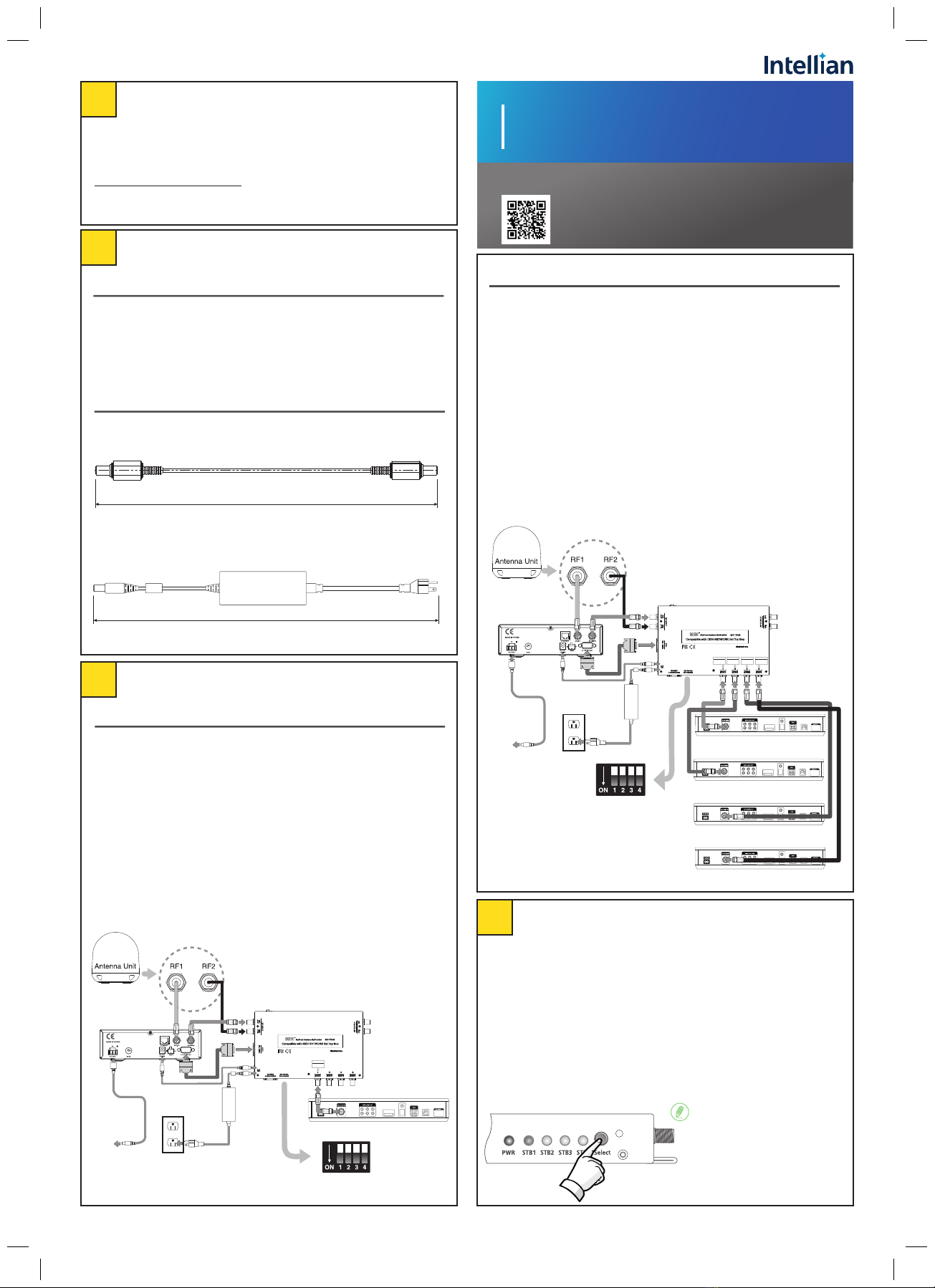
3.2 Multi-Receiver (up to four) Installation
1. Connect the RF cable from the “RF1” connector on the antenna to the
“ANT.RF” connector on the rear panel of the Antenna Control Unit (ACU).
2. Connect the RF cable from the “RECEIVER” connector on the rear panel of the ACU
to the “RF INPUT-RF1” connector on the MIM 2.
3. Connect the RF cable from the “RF2” connector on the antenna to the
“RF INPUT-RF2” connector on the MIM 2.
4. Connect with the RS-232C cable from the “PC Interface” connector on the rear
panel of ACU to the “ACU-RS-232C” connector on the MIM 2.
5. Connect the RF cable from any “TO RECEIVER SATELLITE IN” on the rear of MIM 2
to the “Satellite In” on the rear panel of the receiver.
6. If you have more than one receiver, repeat step 5 to connect RF cables
between the other receivers and the MIM 2 connectors.
7. After completing connections, select one as “Master” by pushing
the “Select” button on the front panel of the MIM 2. Then the LEDs on the front
panel indicate Master STB when you push the button on the front panel of MIM 2.
2.2 Power Requirements
• DC Power Cable: Connect the DC Power Cable to use DC power source from the
i-Series ACU.
1000 mm (39.37”)
• AC-DC Adapter: Connect the AC Adapter if using an AC power source.
(Input 100-240V AC 50/60Hz, Output : 12V DC 3.33A)
350 cm (137.8”)
Dish Wally Receiver #1
DIP Switch setting
for i2/i3/i4/i5/i6 ACU
AC-DC Adapter
(for MIM 2 Unit)
ACU
Antenna Baseplate
DC Power Cable
or
TO RECEIVER
SATELLITE IN
1
DC Power Cable
(for ACU)
Power
source
DIP Switch setting
for i2/i3/i4/i5/i6 ACU
AC-DC Adapter
(for MIM2 unit)
DC Power Cable
Dish Wally Receiver #1
Dish Wally Receiver #3
Dish Wally Receiver #2
Dish Wally Receiver #4
ACU
Antenna Baseplate
or
TO RECEIVER
SATELLITE IN
1
TO RECEIVER
SATELLITE IN
2
TO RECEIVER
SATELLITE IN
3
TO RECEIVER
SATELLITE IN
4
DC Power Cable
(for ACU)
Power
source
4 Select the Master Control Function
1. When you have a receiver connected to “TO RECEIVER SATELLITE IN” number 1
of the MIM 2, the STB1 light turns on when you push the button the first time.
2. If you have other receivers connected, the STB light will move from STB1
through STB4 when the button is pushed. This light means the receiver using
this connection will be the “Master”. You can designate any receiver as the
Master using the “Select” button.
3. When using multiple MIM 2 devices, first select a Master MIM 2. When the
button on the Master MIM 2 is pushed, all lights on the other MIM 2 turns off
because only one MIM 2 can be a Master. Once the Master MIM 2 is selected,
you can select STB1 through STB4 as the Master receiver using the “Select”
button.
NOTE
Please ensure that the Select
button is not accidentally pressed
and switches to another Master
receiver. This can cause loss of
signal message on screen.
NOTE

2
5 Setup the ACU
Doc. No. QG-K00227-V1.0
6 Setup a Single Receiver
5.1 Triple Sat conguration
To Congure the correct set of satellites for MIM 2 to use, ACU needs to
be setup as follows.
6.1 Initial Setup and Mobile Antenna Setup
1. If the receiver is an existing and previously activated receiver, continue with this
guide. For brand new receivers, please us the instructions for
“Setup the Single Receiver - Brand New Receivers” (Refer to the User Guide).
2. After all the cables are connected completely, turn on the power of the ACU. Ensure
that the ACU is tracking “B: DISH110”.
3. After the ACU is tracking “B: DISH110”, power on the Wally Receiver.
When setting up Load Region and Select North America, then select Dish West (even
if you are in the East), this sets the correct Triple Sat sequence automatically.
7 Setup for up to four Wally Receivers
7.1 Setup and Mobile Antenna Setup for 1st Receiver.
1. After all the cables are connected completely, turn on the power of the ACU.
Ensure that the ACU is tracking “B: DISH110”.
2. After the ACU is tracking “B: DISH110”, power on the Wally Receiver.
3. A similar screen to the picture below should appear,
“Install – Test Installation -> Mobile Antenna Setup”.
4. A similar screen to the picture above should appear, “Mobile Antenna Setup”.
5. On the field “Receivers” and select “One”
6. Select mode select Mode type WA 1TV (110,119,129) or Western arc.
7. Select the state that the antenna is located (example: “Southern California”).
8. Click “Scan”, than a menu will pop “Check Switch Status Progress” .
9. Wait for the Check Switch Status Progress to finish.
10. After the test is finished, the receiver will tune in to the last known channel or
channel 103.
11. Check switch status progress bar and Mobile Antenna Setup screen before switch-
ing to view TV.
12. View TV status screen.
Mobile Antenna Setup
Receivers: One
Mode: WA1TV(110,119,129)
State: Southern California
Scan
4
5
6
7
8
6.2 Verifying Triple Satellite Operation
To verify that the receiver is ready for triple satellite operations, please
form the following;
1. Using the remote control, press the “Home” button twice. Select “Settings”->“Diagnostics”.
2. Using the "Down" arrow on the remote
control, Select “Dish”.
Scan
NOTE
If information is missing or an
error is encountered, press
“Test Installation” and
repeat step 8 to step 9 on
“6.1 Initial Setup and Mobile Antenna
Setup”.
NOTE
4. On the field “Receivers” and select “One”.
5. Select Mode select mode type WA 1TV (110,119,129) or Western arc.
6. Select the state that the antenna is located in. (Example: “Southern California”)
7. Click “Scan”, than a menu will pop-up “Check Switch Status Progress”.
8. Verify that all 3 Satellites are present in Tuner 1 (110, 119 and 129),
If not, press “Retest Installation”.
9. The receiver will then proceed on acquiring satellites signals.
(Don’t Power Off Receiver at this time.)
10. The receiver will then download any updates available from Dish Network.
11. Summary display screen will pop-up once the download is complete.
12. Use the arrow keys to navigate to “Watch TV”,and press “Select” button on the
remote control.
13. Channel 103 or Hopper Test Channel should be displayed.
7.2 Setup for 2nd to 4th Receivers
1. Connect the RG6 cable to the MIM 2. (TO RECEIVER SATELLITE IN 2nd ~ 4th port)
2. Press “Select” button on the MIM 2 unit until the desired STB LED lights-up. (STB2 ~ STB4)
Downloading Wally software.
10
13
3. After connecting the receiver at STB2 (~STB4), Power on the 2nd (~4th) Wally
receivers.
This screen will pop-up on the TV screen.
4. Repeat setup process step 3 to step 13 on “7.1 Setup and Mobile Antenna Setup
for 1st Receiver” to set up 2nd, 3rd, and 4th receivers.
11
12
Summery
Watch TV
Watch TV
3. Verify on the screen that the “Switch” is
Mobile and the switch status
“110, 119, and 129” are all checked.
Dish Dish
2
Switch Mobile
SWITCH STATUS
Satellite
Tuner 1
110 119 129 Conn
3
1-1 1-2
Receivers: One
Mode: WA1TV(110,119,129)
State: Southern California
Scan
3
4
5
7
6
Mobile Antenna Setup
Install-Test Installation
Satellite
Tuner 1
110 119 129 Conn
Restart Installation
8
Scan
Mobile Antenna Setup
4-1
4-2
State: Southern California
Receivers: One
Mode: WA1TV(110,119,129)
5.2 Setting Region
Set you region correctly in the ACU.
(Refer to the ACU or MIM 2's User Guide.)
Popular Recording Equipment manuals by other brands

Yamaha
Yamaha VL70-m owner's manual

P3 International
P3 International P5090 operating manual

ADS Technologies
ADS Technologies USBAV-709 quick guide

SMART
SMART Centellis 2000 Installation & use

Barton Musical Circuits
Barton Musical Circuits BMC018.Analog Drum manual

Red Panda
Red Panda RASTER instruction manual


